


PA-FE-TX

170 West Tasman Drive
San Jose, CA 95134-1706
USA
http://www.cisco.com
Cisco Systems, Inc.
Corporate Headquarters
Tel:
800 553-NETS (6387)
408 526-4000
Fax: 408 526-4100
PA-FE-TX and PA-FE-FX Fast
Ethernet 100BaseT Port Adapter
Installation and Configuration
Product Numbers: PA-FE-TX(=) and PA-FE-FX(=)
Platforms Supported: Cisco 7200 Series, Cisco 7000 Series
and Cisco 7500 Series with VIP2, Cisco uBR7200 Series,
Cisco 7100 Series
Note If you ordered this port adapter as a spare, for your convenience Cisco has included a port
adapter installation and configuration note for the Catalyst 5000 series Route Switch
Module/Versatile Interface Processor2 (RSM/VIP2). Your port adapter is fully compatible with the
RSM/VIP2.
Text Part Number: 78-2659-08

Access Registrar, AccessPath, Any to Any, AtmDirector, CCDA, CCDE, CCDP, CCIE, CCNA, CCNP, CCSI, CD-PAC, the Cisco logo, Cisco Certified
Internetwork Expert logo, CiscoLink, the Cisco Management Connection logo, the Cisco NetWorks logo, the Cisco Powered Network logo, Cisco Systems
Capital, the Cisco Systems Capital logo, Cisco Systems Networking Academy, the Cisco Technologies logo, ControlStream, Fast Step, FireRunner,
GigaStack, IGX, JumpStart, Kernel Proxy, MGX, Natural Network Viewer, NetSonar, Network Registrar, Packet, PIX, Point and Click Internetworking,
Policy Builder, Precept, RouteStream, Secure Script, ServiceWay, SlideCast, SMARTnet, StreamView, The Cell, TrafficDirector, TransPath, ViewRunner,
VirtualStream, VisionWay, VlanDirector, Workgroup Director, and Workgroup Stack are trademarks; Changing the Way We Work, Live, Play, and Learn,
Empowering the Internet Generation, The Internet Economy, and The New Internet Economy are service marks; and Asist, BPX, Catalyst, Cisco, Cisco
IOS, the Cisco IOS logo, Cisco Systems, the Cisco Systems logo, the Cisco Systems Cisco Press logo, Enterprise/Solver, EtherChannel, EtherSwitch,
FastHub, FastLink, FastPAD, FastSwitch, IOS, IP/TV, IPX, LightStream, LightSwitch, MICA, NetRanger, Registrar, StrataView Plus, Stratm, TeleRouter,
and VCO are registered trademarks of Cisco Systems, Inc. in the U.S. and certain other countries. All other trademarks mentioned in this document are the
property of their respective owners. (9904R)
PA-FE-TX and PA-FE-FX Fast Ethernet 100Base-T Port Adapter Installation and Configuration
Copyright © 1996—1999 Cisco Systems, Inc.
All rights reserved.

Preface v
Preface
This preface explains the objectives and organization of this document and how to find additional
information on related products and services. This preface contains the following sections:
• Objectives, page v
• Organization, page vi
• Related Documentation, page vi
• Cisco Connection Online, page viii
• Cisco Documentation CD-ROM, page viii
Objectives
This document describes how to install and configure the 100BaseTX and 100BaseFX port adapters
(PA-FE-TX[=] and PA-FE-FX[=]) in the following platforms:
• Cisco 7200 series routers—which consist of the two-slot Cisco 7202, the four-slot Cisco 7204
and Cisco 7204VXR, and the six-slot Cisco 7206 and Cisco 7206VXR
• Cisco uBR7200 series universal broadband routers—which consist of the six-slot (four cable
modem card slots and two port adapter slots) Cisco uBR7246 and the three-slot (two cable
modem card slots and one port adapter slot) Cisco uBR7223
• Cisco 7100 series routers—which consist of the Cisco 7120 series and Cisco 7140 series
• Second-generation Versatile Interface Processor (VIP2) in all Cisco 7500 series routers and in
Cisco 7000 series routers using the 7000 Series Route Switch Processor (RSP7000) and
7000 Series Chassis Interface (RSP7000CI) installed
Note The Cisco 7206VXR and the Cisco 7206 can be used as router shelves in a Cisco AS5800
Universal Access Server. For information about the Cisco 7206VXR and the Cisco 7206 as
router shelves, refer to the Cisco AS5800 Universal Access Server documentation listed in the
“Related Documentation” section on page vi.

Organization
vi
PA-FE-TX and PA-FE-FX Fast Ethernet 100BaseT Port Adapter Installation and Configuration
Organization
This document is organized into the following chapters:
Related Documentation
Your router and the Cisco IOS software running on it contain extensive features and functionality,
which are documented in the following resources:
• ForCisco IOS software configuration information and support, refer tothemodularconfiguration
and modular command reference publications in the Cisco IOS software configuration
documentation set that corresponds to the software release installed on your Cisco hardware.
Note You can access Cisco IOS software configuration and hardware installation and
maintenance documentation on the World Wide Web at http://www.cisco.com,
http://www-china.cisco.com, or http://www-europe.cisco.com.
• For hardware installation and maintenance information on Cisco 7000 series and Cisco 7500
series routers, and the VIP2, refer to the following publications:
— The installation and configuration guide that shipped with your Cisco 7000 series or
Cisco 7500 series router
— Second-GenerationVersatile Interface Processor(VIP2) Installation and Configuration (for
VIP2 users only)
Section Title Description
Chapter 1 Overview Provides information about the PA-FE-TX and
PA-FE-FX 100BaseT port adapters, illustrates
their location in the supported hardware
platforms, and describes their LED displays,
cables, and receptacles
Chapter 2 Preparing for Installation Provides information about safety considerations,
tools required, and procedures you should
perform before the actual installation
Chapter 3 VIP2 and the PA-FE Port Adapters Provides instructions for installing the PA-FEport
adapters on a VIP2 interface processor installed in
a Cisco 7500 or Cisco 7000 series router
Chapter 4 Cisco 7200 Series and the PA-FE
Port Adapters
Provides instructions for installing the PA-FEport
adapters in a Cisco 7200 series router
Chapter 5 Cisco uBR7200 Series and the
PA-FE Port Adapters
Provides instructions for installing the PA-FEport
adapters in a Cisco uBR7200 series universal
broadband router
Chapter 6 Cisco 7100 Series and the PA-FE-TX
and PA-FE-FX
Provides instructions for installing the PA-FEport
adapters in the Cisco 7100 series routers
Chapter 7 Installing PA-FE Port Adapter
Interface Cables
Provides instructions for installing PA-FE port
adapter cables on supported platforms
Chapter 8 Configuring PA-FE Port Adapter
Interfaces
Provides instructions for configuring PA-FE port
adapter interfaces on supported platforms

Preface vii
Related Documentation
• For hardware installation and maintenance information on Cisco 7100 series routers, refer to the
Cisco 7100 Series VPN Router Installation and Configuration Guide publication that shipped
with your Cisco 7100 series router.
• For information on setting up a Virtual Private Network, see the Cisco 7100 Series VPN
Configuration Guide.
• For hardware installation and maintenance information on Cisco 7200 VXR routers, refer to the
Cisco 7200 VXR Installation and Configuration Guide publication that shipped with your
Cisco 7200 VXR router.
• For hardware installation and maintenance information on Cisco 7200 routers, refer to the Cisco
7200 Series Installation and Configuration Guide that shipped with your
Cisco 7200 series router.
• For port adapter hardware and memory configuration guidelines for Cisco 7200 series routers
(including the Cisco 7206VXR or Cisco 7206 as router shelves in a Cisco AS5800 Universal
Access Server), refer to the document Cisco 7200 Series Port Adapter HardwareConfiguration
Guidelines.
• For hardware installation and maintenance information on Cisco uBR7200 series universal
broadband routers, refer to the following publications that shipped with your router:
— Cisco uBR7246 Universal Broadband Router Installation and Configuration Guide
— Cisco uBR7223 Universal Broadband Router Installation and Configuration Guide
• For international agency compliance, safety, and statutory information for interfaces for
Cisco 7500series routers, Cisco 7000 series routers, Cisco 7200 series routers, Cisco 7100 series
routers, and Cisco uBR7200 series universal broadband routers, refer to the following
publications:
— Regulatory Compliance and Safety Information for the Cisco 7500 Series Routers
— Regulatory Compliance and Safety Information for the Cisco 7000 Series Routers
— Regulatory Compliance and Safety Information for the Cisco 7200 Series Routers
— Regulatory Compliance and Safety Information for the Cisco uBR7246 Universal
BroadbandRouter or Regulatory Compliance and Safety Information for the Cisco uBR7223
Universal Broadband Router.
— Regulatory Compliance and Safety Information for the Cisco 7100 Series VPN Routers
• To viewCisco documentation or obtain general informationabout the documentation, refer to the
“Related Documentation” section on page vi, the “Cisco Documentation CD-ROM” section on
page viii, or call Customer Service at 800 553-6387 or 408 526-7208. Customer Service hours
are 5:00 a.m. to 6:00 p.m. Pacific time, Monday through Friday (excluding company holidays).
You can also send e-mail to cs-rep@cisco.com, refer to the Cisco Information Packet that shipped
with your router, or access Cisco documentation on the World Wide Web at
http://www.cisco.com, http://www-china.cisco.com, or http://www-europe.cisco.com.

Cisco Connection Online
viii
PA-FE-TX and PA-FE-FX Fast Ethernet 100BaseT Port Adapter Installation and Configuration
Cisco Connection Online
CiscoConnection Online (CCO) is Cisco Systems’ primary,real-time support channel. Maintenance
customers and partners can self-register on CCO to obtain additional information and services.
Available 24 hours a day, 7 days a week, CCO provides a wealth of standard and value-added
services to Cisco’s customers and business partners. CCO services include product information,
product documentation, software updates, release notes, technical tips, the Bug Navigator,
configuration notes, brochures, descriptions of service offerings, and download access to public and
authorized files.
CCO serves a wide variety of users through two interfaces that are updated and enhanced
simultaneously: a character-based version and a multimedia version that resides on the World Wide
Web (WWW). The character-based CCO supports Zmodem, Kermit, Xmodem, FTP, and Internet
e-mail,and it is excellentfor quick access to information overlowerbandwidths. The WWW version
of CCO provides richly formatted documents with photographs, figures, graphics, and video, as well
as hyperlinks to related information.
You can access CCO in the following ways:
WWW: http://www.cisco.com
WWW: http://www-europe.cisco.com
WWW: http://www-china.cisco.com
Telnet: cco.cisco.com
Modem: From North America, 408 526-8070; from Europe, 33 1 64 46 40 82. Use the following
terminal settings: VT100 emulation; databits: 8; parity: none; stop bits: 1; and connection rates up
to 28.8 kbps.
For a copy of CCO’s Frequently Asked Questions (FAQ), contact cco-help@cisco.com. For
additional information, contact cco-team@cisco.com.
If you are a network administrator and need personal technical assistance with a Cisco product that
isunderwarrantyorcoveredby a maintenance contract, contact Cisco’sTechnical Assistance Center
(TAC) at 800 553-2447, 408 526-7209, or tac@cisco.com. To obtain general information about
Cisco Systems, Cisco products, or upgrades, contact 800 553-6387, 408 526-7208, or
cs-rep@cisco.com.
Cisco Documentation CD-ROM
Ciscodocumentation and additional literature are availablein a CD-ROM package, which ships with
your product. The Documentation CD-ROM,a member of the Cisco Connection Family, is updated
monthly.Therefore, it might be more current than printed documentation. Toorder additional copies
of the Documentation CD-ROM, contact your local sales representative or call customer service.
The CD-ROM package is available as a single package or as an annual subscription. You can also
access Cisco documentation on the World Wide Web at http://www.cisco.com,
http://www-china.cisco.com, or http://www-europe.cisco.com.
If you are reading Cisco product documentation on the WorldWideWeb, you can submit comments
electronically. Click Feedback in the toolbar and select Documentation. After you complete the
form, click Submit to send it to Cisco. We appreciate your comments.

CHAPTER
Overview 1-1
1
Overview
This chapter provides physical and functional overviews of the PA-FE-TX and PA-FE-FX Fast
Ethernet 100BaseT port adapters. The chapter contains the following sections:
• Port Adapter Overview, page 1-1
• Port Adapter Locations on the Supported Platforms, page 1-2
• LEDs, page 1-5
• Receptacles, Cables, and Pinouts, page 1-5
• Fast Ethernet Overview, page 1-9
• IEEE 802.3u 100BaseT Specifications, page 1-10
Port Adapter Overview
The PA-FE-TX and PA-FE-FXport adapters provide a 100-Mbps, 100BaseT Fast Ethernet interface
and support both full-duplex and half-duplex operation. Refer to the “Fast Ethernet Overview”
section on page 1-9 for additional information. Figure 1-1 shows the PA-FE-TX and Figure 1-2
shows the PA-FE-FX.
Note While the VIP2 supports online insertion and removal (OIR), individual port adapters do not.
To replace port adapters, you must first remove the VIP2 from the chassis, then replace port adapters
as required.
Cisco 7100 series routers, Cisco 7200 series routers, and Cisco uBR7200 series universalbroadband
routers support online insertion and removal (OIR) of port adapters.
Figure 1-1 PA-FE-TX—Faceplate View
H4495
ENABLED
MII
LINK
RJ45
FAST ETHERNET
0
Port Adapter Locations on the Supported Platforms
PA-FE-TX and PA-FE-FX Fast Ethernet 100BaseT Port Adapter Installation and Configuration
1-2
Figure 1-2 PA-FE-FX Port Adapter—Faceplate View
The PA-FE can be installed in the following slots on the hardware platforms described in this
document:
• VIP2—Port adapter slot 0 and port adapter slot 1
• Cisco 7200 series routers—Port adapter slot 1 and slot 2 of the Cisco 7202; port adapter slot 1
through slot 4 of the Cisco 7204 and Cisco 7204VXR; port adapter slot 1 through slot 6 of the
Cisco 7206 and Cisco 7206VXR
• Cisco uBR7200 series universal broadband routers—Port adapter slot 1 and slot 2 of the
Cisco uBR7246; port adapter slot 1 of the Cisco uBR7223
• Cisco 7100 series—Port adapter slot 3
Note Port adapters have a handle attached, but this handle is occasionally not shown to allow a full
view of detail on the port adapter’s faceplate.
Port Adapter Locations on the Supported Platforms
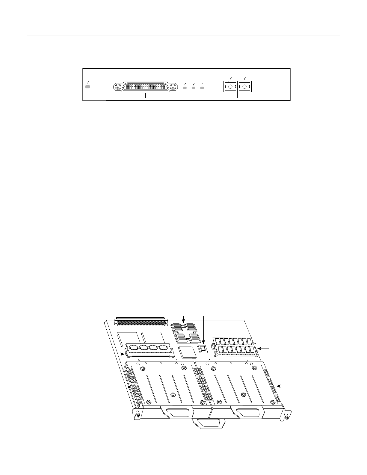
Figure 1-3 and Figure 1-4 show VIP2 models with installed port adapters. With the VIP2 oriented
as shown in Figure 1-3 or Figure 1-4, the left port adapter is in port adapter slot 0, and the right port
adapter is in port adapter slot 1.
In the Cisco 7000, Cisco 7507, and Cisco 7513 chassis, the VIP2 is installed vertically. In the
Cisco 7010 and Cisco 7505 chassis, the VIP2 is installed horizontally.
Figure 1-3 VIP2-15 or VIP2-40 with Two Port Adapters Installed—Horizontal Orientation
H6014
ENABLED
MII
LINK
FIBER
0
FAST ETHERNET
RX
TX
H6448
DRAM
SIMMs
Port adapter
in slot 0
Port adapter
in slot 1
SRAM
DIMM U5
CPU
Boot ROM
Bus connector
U6
U4
U2
Overview 1-3
Port Adapter Locations on the Supported Platforms
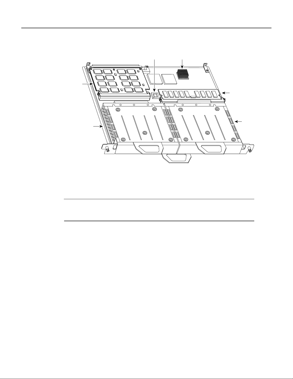
Figure 1-4 VIP2-50 with Two Port Adapters Installed—Horizontal Orientation
In Cisco 7200 series routers, port adapter slots are numbered from the lower left to the upper right,
beginning with port adapter slot 1 and continuing through port adapter slot 2 for the Cisco 7202,
slot 4 for the Cisco 7204 and Cisco 7204VXR, and slot 6 for the Cisco 7206 and Cisco 7206VXR.
Port adapter slot 0 is reserved for the optional Fast Ethernet port on the I/O controller—if present.
Note The I/O controller is available with or without a Fast Ethernet port. You can install both I/O
controller types in all Cisco 7200 series routers; however, when you install an I/O controller with a
Fast Ethernet port in a Cisco 7202, the system software automatically disables the port.
Figure 1-5 showsa Cisco 7206 with installed port adapters and an I/O controller with a Fast Ethernet
port. Not shown are the Cisco 7202, which has two port adapter slots, the Cisco 7204 and
Cisco 7204VXR, which have four port adapter slots, and the Cisco 7206VXR, which has six port
adapter slots. The PA-FE port adapters can be installed in any available port adapter slot in
Cisco 7200 series routers.
Bus connector
SRAM
daughter
card
Boot ROM
CPU
Port adapter
in slot 0
Port
adapter
in slot 1
DRAM DIMM
H10447
Port Adapter Locations on the Supported Platforms
PA-FE-TX and PA-FE-FX Fast Ethernet 100BaseT Port Adapter Installation and Configuration
1-4
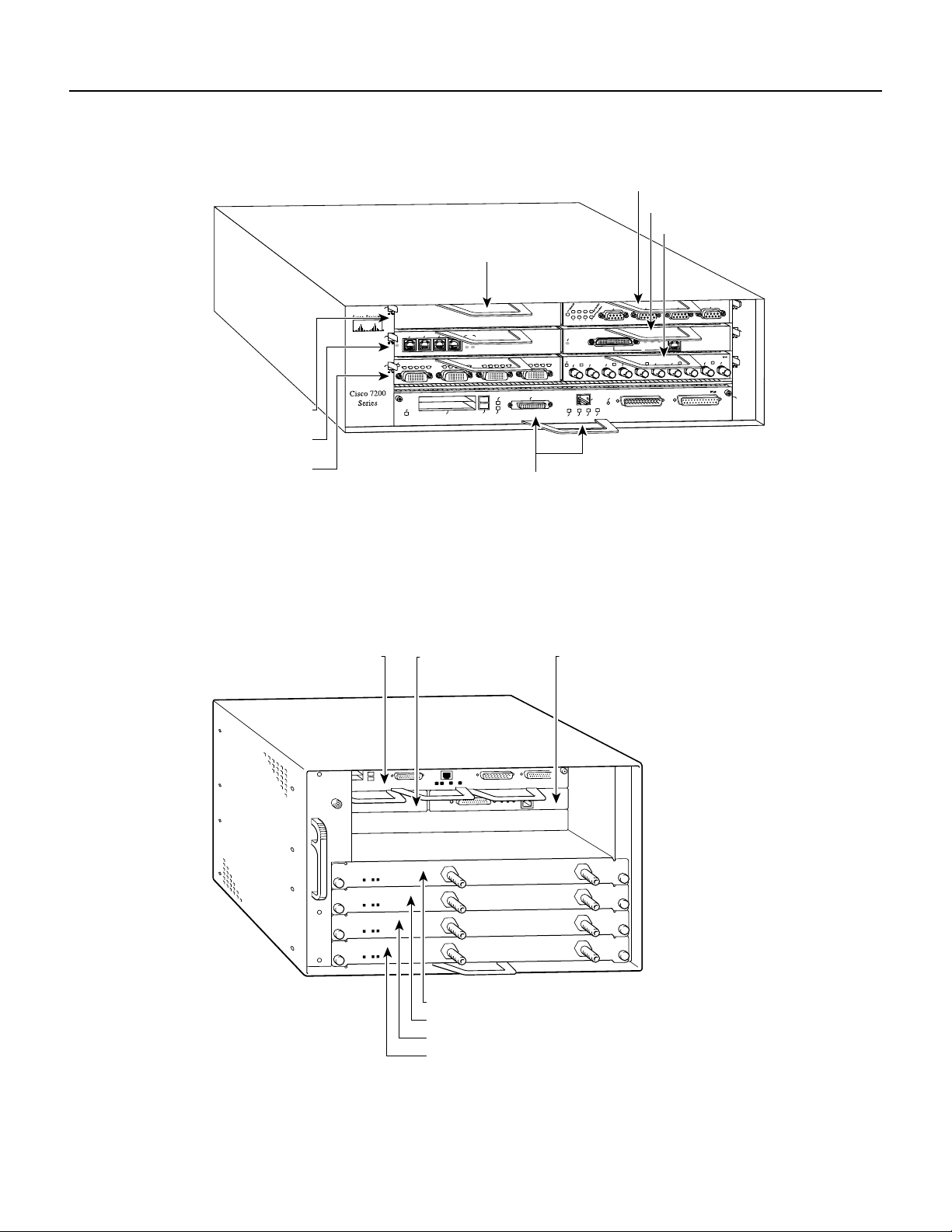
Figure 1-5 Port Adapter Slots in the Cisco 7200 Series—Cisco 7206
Figure 1-6 showsa Cisco uBR7200 series router with port adapters installed. In the Cisco uBR7246,
port adapter slot 1 is in the upper left position, and port adapter slot 2 is in the upper right position.
In the Cisco uBR7223, port adapter slot 1 is in the upper right position. The port adapters are
recessed into the chassis just below the I/O controller.
Figure 1-6 Cisco uBR7200 Series with Port Adapters Installed—Cisco uBR7246
H6422
2
ETHERNET 10BT
ENABLED
0
2
1
3
LINK
0
1
2
3
ENABLED
MII
LINK
RJ45
FAST ETHERNET
0
0
4
1
3
5
6
Port adapter slot 5
Port adapter slot 3
Port adapter slot 1
FAST SERIAL
EN
TD
TC
RD
RC
LB
CD
TD
TC
RD
RC
LB
CD
TD
TC
RD
RC
LB
CD
TD
TC
RD
RC
LB
CD
TOKEN RING
0
1
2
3
ETHERNET-10BFL
EN
RX
0
1
2
3
4
TX
RX
TX
RX
TX
RX
TX
RX
TX
Blank port adapter
Port adapter slot 6
Port adapter slot 4
Port adapter slot 2
MII
EN
RJ45
EN
RJ45
LINK
1O PWR
OK
RJ-45
CPU RESET
FAST ETHERNET INPUT/OUTPUT CONTROLLER
ENABLED
PCMCIA
EJECT
SLOT 0
SLOT 1
FE MII
Port adapter slot 0
H11323
Cable modem card slot 3
Cable modem card slot 4
Cable modem card slot 5
Cable modem card slot 6
Port adapter slot 0
(I/O controller)
Port adapter slot 1
(blank)
Port adapter slot 2

Overview 1-5
LEDs
LEDs
The PA-FE-TX and the PA-FE-FX have an enabled LED, standard on all port adapters, and a bank
of three status LEDs for the ports. After system initialization, the enabled LED goes on to indicate
that the PA-FE has been enabled for operation. (The LEDs are shown in Figure 1-7.)
Figure 1-7 LEDs on the PA-FE Port Adapter—Partial Faceplate View of PA-FE-TX
The following conditions must be met before the enabled LED goes on:
• The PA-FE is correctly connected and receiving power.
• The FE-equipped card or chassis contains a valid microcode version that has been downloaded
successfully.
• The bus recognizes the PA-FE port adapter or PA-FE-equipped VIP2.
If any of these conditions is not met, or if the initialization fails for other reasons, the enabled LED
does not go on.
Following are the three status LEDs and an explanation of what each indicates:
• MII—On when the MII port is selected as the active port by the controller.
• Link—When the RJ-45 or SC port is active, this LED is on when the port adapter is receiving a
carrier signal from the network. When the MII port is active, this LED is an indication of network
activity, and it flickers on and off proportionally to this activity.
• RJ-45 (or FIBER on PA-FE-FX)—On when the RJ-45 (or FIBER) port is selected as the active
port by the controller.
Either the MII LED or the RJ-45 (or FIBER) LED should be on at any one time; never both.
Receptacles, Cables, and Pinouts
Each Fast Ethernet port on the PA-FE-TX has an RJ-45 connector to attach to Category 5 unshielded
twisted-pair (UTP) for 100BaseTX, and a MII connector that permits connection through external
transceivers to multimode fiber for 100BaseFX, or to Category 3, 4, and 5 UTP or foil twisted-pair
(FTP) for 100BaseT4 physical media. Only one connector can be used at one time. The RJ-45
connection does not require an external transceiver. The MII connection (a 40-pin, D-shell type
connector) requires an external physical sublayer (PHY) and an external transceiver.
Each Fast Ethernet port on the PA-FE-FX port adapter has an SC-type fiber-optic connector for
100BaseFX, and an MII connector that permits connection through external transceivers to
multimode fiber for 100BaseFX, or to Category 3, 4, and 5 UTP or STP for 100BaseT4 physical
media. Only one connector can be used at one time. The MII connection (a 40-pin, D-shell type
connector) requires an external physical sublayer (PHY) and an external transceiver.
H4710
Receptacles, Cables, and Pinouts
PA-FE-TX and PA-FE-FX Fast Ethernet 100BaseT Port Adapter Installation and Configuration
1-6
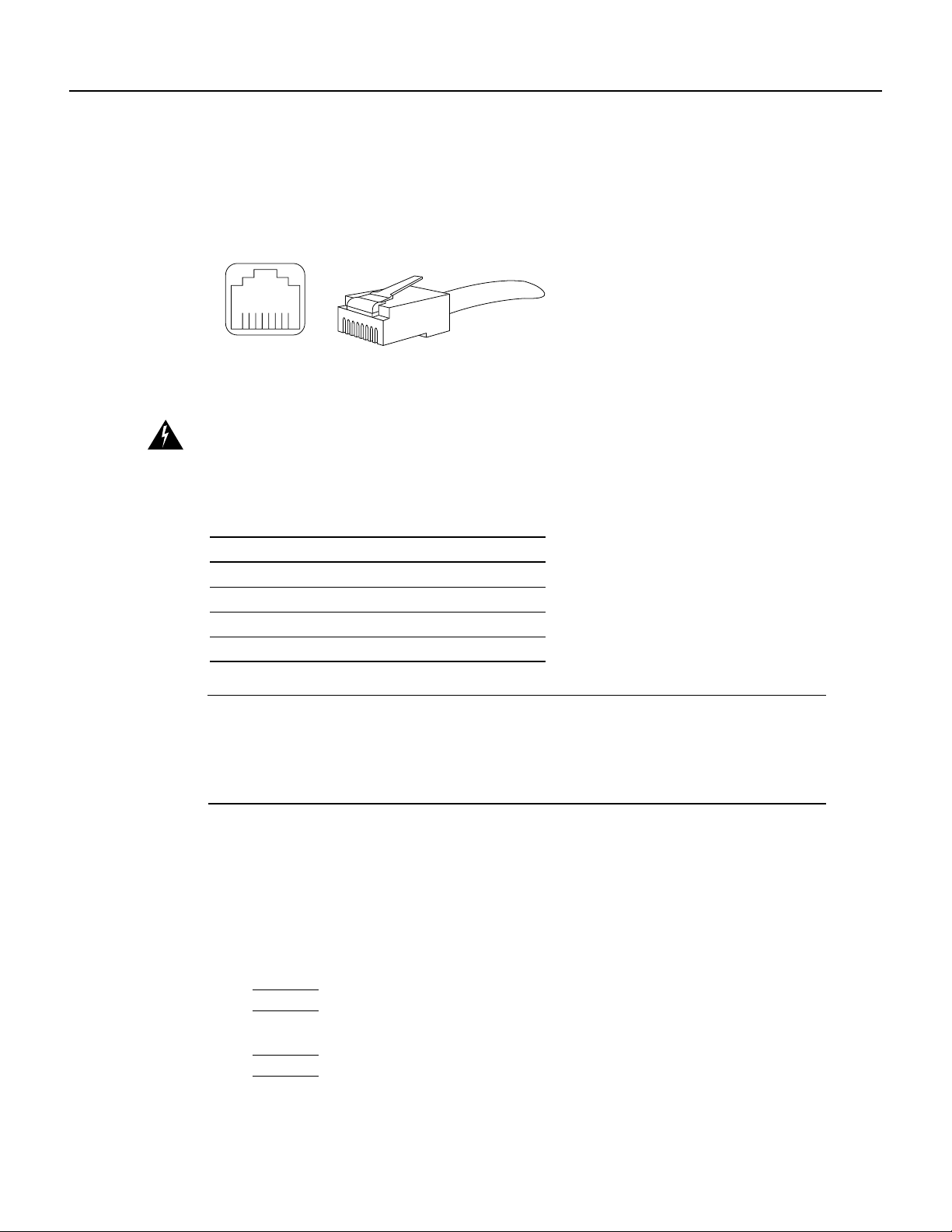
Figure 1-8 showsthe RJ-45 cable connectors. Cisco Systems does not supply Category5 UTP RJ-45
cables; these cables are available commercially. Table 1-1 lists the pinouts and signals for the
PA-FE-TX RJ-45 connectors.
Figure 1-8 PA-FE-TX RJ-45 Connections—Plug and Receptacle
Warning
The ports labeled “Ethernet,” “10BaseT,” “Token Ring,” “Console,” and “AUX” are
safety extra-low voltage (SELV) circuits. SELV circuits should only be connected to other SELV
circuits. Because the BRI circuits are treated like telephone-network voltage, avoid connecting the
SELV circuit to the telephone network voltage (TNV) circuits.
Table 1-1 PA-FE-TX RJ-45 Connector Pinout
Note Referring to the RJ-45 pinout in Table 1-1, proper common-mode line terminations should be
used for the unused Category 5, UTP cable pairs 4/5 and 7/8. Common-mode termination reduces
the contributions to electromagnetic interference (EMI) and susceptibility to common-mode
sources. Wirepairs 4/5 and 7/8 are actively terminated in the RJ-45, 100BaseTX port circuitry in the
PA-FE-TX.
Depending on your RJ-45 interface cabling requirements, use the pinouts in Figure 1-9 and
Figure 1-10.
Figure 1-9 Straight-Through Cable Pinout—PA-FE-TX RJ-45 Connection to a Hub or
Repeater
Pin Description
1 Receive Data + (RxD+)
2 RxD–
3 Transmit Data + (TxD+)
6 TxD–
H2936
8 7 6 5 4 3 2 1
RJ-45 connector
Hub or repeaterFEIP
3 TxD+
6 TxD–
1 RxD+
2 RxD–
3 RxD+
6 RxD–
1 TxD+
2 TxD–
H3137

Overview 1-7
Receptacles, Cables, and Pinouts
Figure 1-10 Crossover Cable Pinout—PA-FE-TX RJ-45 Connections Between Hubs and
Repeaters
Figure 1-11 shows the duplex SC connector (one required for both transmit and receive), and
Figure 1-12 shows the simplex SC connector (two required, one for each transmit and receive) used
for PA-FE-FX optical-fiber connections. These multimode optical-fiber cables are commercially
available, and are not available from Cisco Systems.
Figure 1-11 PA-FE-FX Duplex SC Connector
Figure 1-12 PA-FE-FX Simplex SC Connector
Depending on the type of media you use between the MII connection on the port adapter and your
switch or hub, the network side of your 100BaseT transceivershould be appropriately equipped with
ST-type connectors (for optical fiber), BNC connectors, and so forth. Figure 1-13 shows the pin
orientation of the female MII connector on the port adapter. The port adapters are field-replaceable
units (FRUs).
The MII receptacle uses 2-56 screw-type locks, called jackscrews (shown in Figure 1-13), to secure
the cable or transceiver to the MII port. MII cables and transceivers have knurled thumbscrews that
you fasten to the jackscrews on the PA-FE-TX’s MII connector.Use the jackscrews to provide strain
relief for your MII cable. Figure 1-13 shows the MII female connector (receptacle).
Caution Before you attach your MII transceiver to the MII receptacle on your PA-FE port adapter,
ensure that your MII transceiver responds to physical sublayer (PHY) address 0 per section 22.2.4.4.
“PHY Address” of the IEEE 802.3u specification; otherwise, interface problems might result.
Confirm that this capability is available on your MII transceiver with the transceiver’s vendor or in
the transceiver’s documentation. If a selection for Isolation Mode is available, we recommend you
use this setting (if no mention is made of PHY addressing).
Hub or repeater
3 TxD+
6 TxD–
1 RxD+
2 RxD–
3 TxD+
6 TxD–
1 RxD+
2 RxD–
H3138
Hub or repeater
H2214
H2399

Receptacles, Cables, and Pinouts
PA-FE-TX and PA-FE-FX Fast Ethernet 100BaseT Port Adapter Installation and Configuration
1-8
Figure 1-13 PA-FE-TX or PA-FE-FX MII Connection—Receptacle
Table 1-2 lists the MII connector pinout and signals. MII cables are available commercially and are
not availablefrom Cisco Systems. Table 1-2 refers to MII cables used between the MII connector on
the PA-FE-TX and an appropriate transceiver. The connection between this transceiver and your
network can be Category 3, 4, or 5, 150-ohm UTP or FTP, or multimode optical fiber.
Table 1-2 MII Connector Pinout
Pin
1
1 Any pins not indicated are not used.
In Out In/Out Description
14–17 – Yes – Transmit Data (TxD)
12 Yes – – Transmit Clock (Tx_CLK)
2
2 Tx_CLK and Rx_CLK are generated by the external transceiver.
11 – Yes – Transmit Error (Tx_ER)
13 – Yes – Transmit Enable (Tx_EN)
3 – Yes – MII Data Clock (MDC)
4–7 Yes – – Receive Data (RxD)
9 Yes – – Receive Clock (Rx_CLK)
10 Yes – – Receive Error (Rx_ER)
8 Yes – – Receive Data Valid (Rx_DV)
18 Yes – – Collision (COL)
19 Yes – – Carrier Sense (CRS)
2 – – Yes MII Data Input/Output (MDIO)
22–39 – – – Common (ground)
1, 20, 21, 40 – – – +5.0 volts (V)
Jackscrew Pin 1
Pin 21
H2943

Overview 1-9
Fast Ethernet Overview
Fast Ethernet Overview
The term Ethernet is commonly used for all carrier sense multiple access collision detect
(CSMA/CD),LANs that generally conform to Ethernet specifications, including Fast Ethernet under
IEEE 802.3u.
Note 100BaseTX is intended for Environment A, and 100BaseFX is intended for Environment B.
IEEE 802.3u is well suited to applications where a local communication medium must carry
sporadic,occasionallyheavytraffic at high peak data rates. Stations on a CSMA/CD LAN can access
the network at any time. Before sending data, the station listens to the network to see if it is already
in use. If it is, the station waits until the network is not in use, then transmits; this is half-duplex
operation. A collision occurs when two stations listen for network traffic, hear none, and transmit
almost simultaneously. When this happens, both transmissions are damaged, and the stations must
retransmit. The stations detect the collision and use backoff algorithms to determine when they
should retransmit.
Both Ethernet and IEEE 802.3u are broadcast networks, which means that all stations see all
transmissions. Each station must examine received frames to determine whether it is the intended
destination and, if it is, pass the frame to a higher protocol layer for processing.
IEEE 802.3u specifies the following different physical layers for 100BaseT:
• 100BaseTX—100BaseT, half and full duplex over Category 5 unshielded twisted-pair (UTP),
Electronics Industry Association/Telecommunications Industry Association
[EIA/TIA]–568-compliant cable
• 100BaseFX—100BaseT, half and full duplex over optical fiber
• 100BaseT4—100BaseT, half and full duplex over Category 3, 4, or 5 UTP or foil twisted-pair
(FTP) cabling with four pairs; also called 4T+ or T2, which is 2-pair UTP over Category 3 cable.
Each physical layer protocol has a name that summarizes its characteristics in the format
speed/signaling method/segment length, where speed is the LAN speed in Mbps, signaling method
is either baseband or broadband, and segment length is typically the maximum length between
stations in hundreds of meters. Therefore, 100BaseT specifies a 100-Mbps, baseband LAN with
maximum network segments.

IEEE 802.3u 100BaseT Specifications
PA-FE-TX and PA-FE-FX Fast Ethernet 100BaseT Port Adapter Installation and Configuration
1-10
IEEE 802.3u 100BaseT Specifications
Table 1-3 lists the cabling specifications for 100-Mbps Fast Ethernet transmission over UTP, FTP,
and fiber-optic cables. Table 1-4 summarizes IEEE 802.3u 100BaseT physical characteristics.
Table 1-3 Specifications and Connection Limits for 100-Mbps Transmission
Table 1-4 IEEE 802.3u Physical Characteristics
Parameter RJ-45 MII SC-Type
Cable specification Category 5
1
UTP
2
, 22 to 24 AWG
1 EIA/TIA-568 or EIA-TIA-568 TSB-36 compliant.
2 Cisco Systems does not supply Category 5 UTP RJ-45 or 150-ohm FTP MII cables. Both are available commercially.
Category 3, 4, or 5, 150-ohm UTP or FTP,
or multimode optical fiber
62.5/125 multimode optical
fiber
Maximum cable length – 1.64 ft (0.5 m) (MII-to-MII cable
3
)
3 This is the cable between the MII port on the PA-FE port adapter and the appropriate transceiver.
–
Maximum segment length 328 ft (100 m) for 100BaseTX 3.28 ft (1 m)
4
or 1,312 ft (400 m) for
100BaseFX
4 This length is specifically between any two stations on a repeated segment.
328 ft (100 m)
Maximum network length 656 ft (200 m)
4
(with 1 repeater) – 656 ft (200 m)
4
(with 1
repeater)
Parameter 100BaseFX 100BaseTX
Data rate (Mbps) 100 100
Signaling method Baseband Baseband
Maximum segment length (meters) 100 m between repeaters 100 m between DTE
1
and repeaters
1 DTE = data terminal equipment.
Media SC-type: dual simplex or single duplex for Rx and Tx RJ-45MII
Topology Star or Hub Star or Hub

CHAPTER
Preparing for Installation 2-1
2
Preparing for Installation
This chapter describes the general equipment, safety,and site preparation requirements for installing
the PA-FE-TX and PA-FE-FX Fast Ethernet port adapters. The chapter contains the following
sections:
• List of Parts and Tools, page 2-1
• Software and Hardware Requirements, page 2-2
• Safety Guidelines, page 2-3
• FCC Class B Compliance, page 2-6
List of Parts and Tools
You need the following tools and parts to install a port adapter. If you need additional equipment,
contact a service representative for ordering information.
• PA-FE-TX(=) or PA-FE-FX(=) port adapter, and one of the following:
— VIP2-15(=), VIP2-20, VIP2-40(=), or VIP2-50(=) (For specific VIP2 model information,
see the “Software and Hardware Requirements” section on page 2-2)
— Cisco 7100 series router with at least one available port adapter slot
— Cisco 7200 series router with at least one available port adapter slot
— Cisco uBR7200 series universal broadband router with at least one available port adapter slot
• Cables appropriate for the port adapter’sinterfaces (RJ-45 and multimode optical fiber cables are
not available from Cisco Systems; they are available from outside commercial cable vendors)
• Number 1 Phillips and a 3/16-inch, flat-blade screwdriver
• Your own ESD-prevention equipment or the disposable grounding wrist strap included with all
upgrade kits, FRUs, and spares

Software and Hardware Requirements
PA-FE-TX and PA-FE-FX Fast Ethernet 100BaseT Port Adapter Installation and Configuration
2-2
Software and Hardware Requirements
Table 2-1 lists the minimum Cisco IOS software release required to use the PA-FE-TX and
PA-FE-FX in supported router platforms.
Table 2-1 PA-FE-TX and PA-FE-FX Software Requirements
In Cisco 7000 series or Cisco 7500 series routers, PA-FE-FX and PA-FE-TX require the following
VIP2 models:
• VIP2-15 (1 MB of SRAM, 8 MB of DRAM)
• VIP2-40 (2 MB of SRAM, 32 MB of DRAM)
• VIP2-50 (4 to 8 MB of SRAM, 32 to 128 MB of DRAM)
Note The minimum recommended VIP2 model is a VIP2-15. The maximum transmission unit
(MTU) size available for two Fast Ethernet port adapters on a VIP2 require the additional VIP2
SRAM availableon VIP2-15 models, or greater,to ensure adequate packet buffers.The VIP2-15 can
also be used if you only have one Fast Ethernet port adapter on a VIP2.
The VIP2-10 has certain configuration constraints because of its limited SRAM for packet buffers;
therefore, we do not recommend you use VIP2-10 with Fast Ethernet port adapters.
Router Platform Recommended Minimum Cisco IOS Release
Cisco 7000 series and Cisco 7500 series
• With VIP2-15(=) or VIP2-40(=) Cisco IOS Release 11.1(472) or a later release of Cisco IOS Release 11.1
Cisco IOS Release 11.1(16)CA or a later release of Cisco IOS Release 11.1 CA
Cisco IOS Release 11.2(1) or a later release of Cisco IOS Release 11.2
Cisco IOS Release 11.2(5)P or a later release of Cisco IOS Release 11.2 P
• With VIP2-50(=) Cisco IOS Release 11.1(14)CA or a later release of Cisco IOS Release 11.1 CA
Cisco 7200 series
• Cisco 7204VXR and Cisco 7206VXR Cisco IOS Release 12.0(2)XE2 or a later release of Cisco IOS Release 12.0 XE
Cisco IOS Release 12.0(3)T or a later release of Cisco IOS Release 12.0 T
• Cisco 7204 and Cisco 7206 Cisco IOS Release 11.1(472) or a later release of Cisco IOS Release 11.1
Cisco IOS Release 11.1(16)CA or a later release of Cisco IOS Release 11.1 CA
Cisco IOS Release 11.2(1) or a later release of Cisco IOS Release 11.2
Cisco IOS Release 11.2(5)P or a later release of Cisco IOS Release 11.2 P
• Cisco 7202 Cisco IOS Release 11.1(19)CC1 or a later release of Cisco IOS Release 11.1 CC
Cisco IOS Release 11.3(4)AA or a later release of Cisco IOS Release 11.3 AA
• Cisco 7206 router shelf Cisco IOS Release 11.3(2)AA or a later release of Cisco IOS Release 11.3 AA
Cisco uBR7200 series
• Cisco uBR7246 and Cisco uBR7223 Cisco IOS Release 11.3(7)NA or a later release of Cisco IOS Release 11.3 NA
Cisco IOS Release 12.0(3)T or a later release of Cisco IOS Release 12.0 T
Cisco 7100 series
• Cisco 7120 series and Cisco 7140 series Cisco IOS Release 12.0(4)XE or a later release of Cisco IOS Release 12.0 XE
Cisco IOS Release 12.0(5)T or a later release of Cisco IOS Release 12.0 T

Preparing for Installation 2-3
Safety Guidelines
Caution The VIP2 requires that Cisco 7000 series routers have the RSP7000 and RSP7000CI
installed. The VIP2 will not operate properly with the Route Processor (RP), Switch Processor (SP),
or Silicon Switch Processor (SSP) installed in a Cisco 7000 series router.
Safety Guidelines
Following are safety guidelines that you should follow when working with any equipment that
connects to electrical power or telephone wiring.
Safety Warnings
Safety warnings appear throughout this publication in procedures that, if performed incorrectly,
might harm you. A warning symbol precedes each warning statement.
Warning Thiswarning symbol means danger.Youare in a situation that could cause bodily injury.
Before you work on any equipment, be aware of the hazards involved with electrical circuitry and
be familiar with standard practices for preventing accidents. To see translations of the warnings that
appear in this publication, refer to the RegulatoryCompliance and Safety Information document that
accompanied this device.
Waarschuwing Dit waarschuwingssymbool betekent gevaar. U verkeert in een situatie die
lichamelijk letsel kan veroorzaken. Voordat u aan enige apparatuur gaat werken, dient u zich bewust
te zijn van de bij elektrische schakelingen betrokken risico's en dient u op de hoogte te zijn van
standaard maatregelen om ongelukken te voorkomen. Voor vertalingen van de waarschuwingen die
in deze publicatie verschijnen, kunt u het document Regulatory Compliance and Safety Information
(Informatie over naleving van veiligheids- en andere voorschriften) raadplegen dat bij dit toestel is
ingesloten.
Varoitus Tämävaroitusmerkkimerkitsee vaaraa. Olet tilanteessa,jokavoijohtaa ruumiinvammaan.
Ennen kuin työskentelet minkään laitteiston parissa, ota selvää sähkökytkentöihin liittyvistä
vaaroista ja tavanomaisista onnettomuuksien ehkäisykeinoista. Tässä julkaisussa esiintyvien
varoitusten käännökset löydät laitteen mukana olevasta Regulatory Compliance and Safety
Information -kirjasesta (määräysten noudattaminen ja tietoa turvallisuudesta).
Attention Ce symbole d'avertissement indique un danger. Vous vous trouvez dans une situation
pouvant causer des blessures ou des dommages corporels. Avant de travailler sur un équipement,
soyez conscient des dangers posés par les circuits électriques et familiarisez-vous avec les
procédures couramment utilisées pour éviter les accidents. Pour prendre connaissance des
traductions d’avertissements figurant dans cette publication, consultez le document Regulatory
Compliance and Safety Information (Conformité aux règlements et consignes de sécurité) qui
accompagne cet appareil.
Warnung Dieses Warnsymbol bedeutet Gefahr. Sie befinden sich in einer Situation, die zu einer
Körperverletzungführen könnte. Bevor Sie mit der Arbeit an irgendeinem Gerät beginnen, seien Sie
sich der mit elektrischen Stromkreisen verbundenen Gefahren und der Standardpraktiken zur
Vermeidung von Unfällen bewußt. Übersetzungen der in dieser Veröffentlichung enthaltenen
Warnhinweise finden Sie im Dokument Regulatory Compliance and Safety Information
(Informationen zu behördlichen Vorschriften und Sicherheit), das zusammen mit diesem Gerät
geliefert wurde.
Avvertenza Questo simbolo di avvertenza indica un pericolo. La situazione potrebbe causare
infortuni alle persone. Prima di lavorare su qualsiasi apparecchiatura, occorre conoscere i pericoli
relativiai circuiti elettrici ed essere al corrente delle pratiche standard per la prevenzione di incidenti.

Safety Guidelines
PA-FE-TX and PA-FE-FX Fast Ethernet 100BaseT Port Adapter Installation and Configuration
2-4
La traduzione delle avvertenze riportate in questa pubblicazione si trova nel documento Regulatory
Compliance and Safety Information (Conformità alle norme e informazioni sulla sicurezza) che
accompagna questo dispositivo.
Advarsel Dette varselsymbolet betyr fare. Du befinner deg i en situasjon som kan føre til
personskade. Før du utfører arbeid på utstyr, må du vare oppmerksom på de faremomentene som
elektriskekretser innebærer,samt gjøre deg kjent med vanligpraksis nårdet gjelder å unngå ulykker.
Hvis du vil se oversettelser av de advarslene som finnes i denne publikasjonen, kan du se i
dokumentet Regulatory Compliance and Safety Information (Overholdelse av forskrifter og
sikkerhetsinformasjon) som ble levert med denne enheten.
Aviso Estesímbolo de aviso indica perigo. Encontra-se numa situação que lhe poderá causar danos
físicos. Antes de começar a trabalhar com qualquer equipamento, familiarize-se com os perigos
relacionados com circuitos eléctricos, e com quaisquer práticas comuns que possam prevenir
possíveis acidentes. Para ver as traduções dos avisos que constam desta publicação, consulte o
documentoRegulatoryCompliance and SafetyInformation(Informaçãode Segurança e Disposições
Reguladoras) que acompanha este dispositivo.
¡Advertencia! Este símbolo de aviso significa peligro. Existe riesgo para su integridad física. Antes
de manipular cualquier equipo, considerar los riesgos que entraña la corriente eléctrica y
familiarizarse con los procedimientos estándar de prevención de accidentes. Para ver una traducción
de las advertencias que aparecen en esta publicación, consultar el documento titulado Regulatory
Compliance and Safety Information (Información sobre seguridad y conformidad con las
disposiciones reglamentarias) que se acompaña con este dispositivo.
Varning! Denna varningssymbol signalerar fara. Du befinner dig i en situation som kan leda till
personskada. Innan du utför arbete på någon utrustning måste du vara medveten om farorna med
elkretsar och känna till vanligt förfarande för att förebygga skador. Se förklaringar av de varningar
som förkommer i denna publikation i dokumentet Regulatory Compliance and Safety Information
(Efterrättelse av föreskrifter och säkerhetsinformation), vilket medföljer denna anordning.
Electrical Equipment Guidelines
Follow these basic guidelines when working with any electrical equipment:
• Before beginning any procedures requiring access to the chassis interior, locate the emergency
power-off switch for the room in which you are working.
• Disconnect all power and external cables before moving a chassis.
• Do not work alone when potentially hazardous conditions exist and never assume that power has
been disconnected from a circuit; always check.
• Do not perform any action that creates a potential hazard to people or makes the equipment
unsafe. Carefully examine your work area for possible hazards such as moist floors, ungrounded
power extension cables, and missing safety grounds.
Telephone Wiring Guidelines
Use the following guidelines when working with any equipment that is connected to telephone
wiring or to other network cabling:
• Never install telephone wiring during a lightning storm.
• Never install telephone jacks in wet locations unless the jack is specifically designed for wet
locations.
 Loading...