


NetXtreme II Network Adapter 5709
Table of contents
 Loading...
User Guide NetXtreme II
January 2010
Broadcom NetXtreme II™ Network Adapter User
Guide
• Introduction
• Functionality and Features
•Teaming
• Virtual LANs (VLANs)
• Manageability
• Installing the Hardware
• Installing the Driver Software
• Broadcom Boot Agent Driver Software
• NDIS2 Driver Software
• ODI Driver Software
• Linux Driver Software
• NetWare Driver Software
• Windows Driver Software
• Installing Management Applications
•Using iSCSI
• Configuring Teaming
• Using Broadcom Advanced Control Suite 3
• User Diagnostics
• Specifications
• Regulatory Information
• Troubleshooting
Information in this document is subject to change without notice.
© 2010 Broadcom Corporation. All rights reserved.
This document is protected by copyright and is distributed under licenses restricting its use, copying, distribution, and
decompilation. No part of this document may be reproduced in any form by any means without prior written authorization of
Broadcom Corporation. Documentation is provided as is without warranty of any kind, either express or implied, including
any kind of implied or express warranty of non-infringement or the implied warranties of merchantability or fitness for a
particular purpose.
Broadcom Corporation reserves the right to make changes without further notice to any products or data herein to improve
reliability, function, or design. Information furnished by Broadcom Corporation is believed to be accurate and reliable.
However, Broadcom Corporation does not assume any liability arising out of the application or use of this information, nor
Broadcom Corporation
Document ENGSRVT52-CDUM100-R Broadcom NetXtreme II™ Network Adapter User Guide Page 1

NetXtreme II User Guide
January 2010
the application or use of any product or circuit described herein, neither does it convey any license under its patent rights or
the rights of others.
Broadcom, the pulse logo, Connecting everything, the Connecting everything logo, NetXtreme, Ethernet@Wirespeed,
LiveLink, and Smart Load Balancing are among the trademarks of Broadcom Corporation and/or its affiliates in the United
States, certain other countries, and/or the EU. Microsoft and Windows are trademarks of Microsoft Corporation. Linux is a
trademark of Linus Torvalds. NetWare is a trademark of Novell Corporation. Intel is a trademark of Intel Corporation. Magic
Packet is a trademark of Advanced Micro Devices, Inc. Red Hat is a trademark of Red Hat, Inc. PCI Express is a trademark
of PCI-SIG. Any other trademarks or trade names mentioned are the property of their respective owners.
Initial release: December 2005
Last revised: January 2010
ENGSRVT52-CDUM100-R
Broadcom Corporation
Page 2 Broadcom NetXtreme II™ Network Adapter User Guide Document ENGSRVT52-CDUM100-R

User Guide NetXtreme II
January 2010
Functionality and Features: Broadcom
NetXtreme II™ Network Adapter User Guide
• Functional Description
•Features
FUNCTIONAL DESCRIPTION
The Broadcom NetXtreme II adapter is a new class of Gigabit Ethernet (GbE) and 10 GbE converged network interface
controller (C-NIC) that can simultaneously perform accelerated data networking and storage networking on a standard
Ethernet network. The C-NIC offers acceleration for all popular protocols used in the data center, such as:
• TCP Offload Engine (TOE) for accelerating TCP over 1 GbE, 2.5 GbE, and 10 GbE
• Internet Small Computer Systems Interface (iSCSI) offload for accelerating network storage access featuring
centralized boot functionality (iSCSI boot)
NOTE: Separate licences are required for all offloading technologies.
Enterprise networks that use multiple protocols and multiple network fabrics benefit from the C-NICs ability to combine data
communications, storage, and clustering over a single Ethernet fabric by boosting server CPU processing performance and
memory utilization while alleviating I/O bottlenecks.
The Broadcom NetXtreme II adapter includes a 10/100/1000-Mbps or 10-Gbps Ethernet MAC with both half-duplex and fullduplex capability and a 10/100/1000-Mbps or 10-Gbps PHY. The transceiver is fully compatible with the IEEE 802.3 standard
for auto-negotiation of speed.
Using the Broadcom teaming software, you can split your network into virtual LANs (VLANs) as well as group multiple
network adapters together into teams to provide network load balancing and fault tolerance functionality. See Configuring
Teaming and Broadcom Gigabit Ethernet Teaming Services for detailed information about teaming. See Virtual LANs, for a
description of VLANs. See Configuring Teaming for instructions on configuring teaming and creating VLANs on Windows
operating systems.
Broadcom Corporation
Document ENGSRVT52-CDUM100-R Functionality and Features: Broadcom NetXtreme II™ Network Adapter User Guide Page 3

NetXtreme II User Guide
January 2010
FEATURES
The following is a list of the Broadcom NetXtreme II adapter features:
• TCP Offload Engine (TOE)
• Internet Small Computer Systems Interface (iSCSI) offload
• Single-chip solution
• Integrated 10/100/1000BASE-T transceivers
• Integrated 10GBASE-T transceivers
• 10/100/1000 triple-speed MAC
• Host interfaces
• SerDes interface for optical transceiver connection
• PCI Express 1.0a x4 (Gigabit Ethernet)
• PCI Express Gen2 x8 (10 Gigabit Ethernet)
• Full fast-path TCP offload
• Zero copy capable hardware
• Other performance features
• TCP, IP, UDP checksum
• TCP segmentation
• Adaptive interrupts
• Receive Side Scaling (RSS)
• Manageability
• Broadcom Advanced Control Suite 3 diagnostic and configuration software suite
• Supports PXE 2.0 specification (Linux Red Hat PXE Server, SUSE Linux Enterprise Server, Windows 2000 Server,
Windows Server 2003, Windows Server 2008, Windows Server 2008 R2, Intel APITEST, DOS UNDI)
• Wake on LAN support
• Universal Management Port (UMP) support
• Statistics for SNMP MIB II, Ethernet-like MIB, and Ethernet MIB (IEEE Std 802.3z, Clause 30)
• SMBus controller
• ACPI 1.1a compliant (multiple power modes)
• IPMI support
• Advanced network features
• Jumbo frames (up to 9 KB). The OS and the link partner must support jumbo frames.
• Virtual LANs
• IEEE Std 802.3ad Teaming
• Smart Load Balancing Teaming
• Smart Load Balancing TOE Teaming (with the correct configuration)
• Flow Control (IEEE Std 802.3x)
• LiveLink™ (supported in both the 32-bit and 64-bit Windows operating systems)
• Logical Link Control (IEEE Std 802.2)
• Layer-2 Priority Encoding (IEEE Std 802.1p)
• High-speed on-chip RISC processor
• Up to 4 classes of service (CoS)
• Up to 4 send rings and receive rings
Broadcom Corporation
Page 4 Features Document ENGSRVT52-CDUM100-R

User Guide NetXtreme II
January 2010
• Integrated 96 KB frame buffer memory
• GMII/MII Management Interface
• Four unique MAC unicast addresses
• Support for multicast addresses via 128 bits hashing hardware function
• Serial flash NVRAM memory
• JTAG support
• PCI Power Management Interface (v1.1)
• 64-bit BAR support
• EM64T processor support
• AMD-64 processor support
• 1.2 V core voltage, 0.13 µm process
• iSCSI Boot support
TCP OFFLOAD ENGINE (TOE)
The TCP/IP protocol suite is used to provide transport services for a wide range of applications for the Internet, LAN, and
for file transfer. Without the TCP Offload Engine, the TCP/IP protocol suite runs on the host CPU, consuming a very high
percentage of its resources and leaving little resources for the applications. With the use of the Broadcom NetXtreme II
adapter, the TCP/IP processing can be moved to hardware, freeing the CPU for more important tasks such as application
processing.
The Broadcom NetXtreme II adapter's TOE functionality allows simultaneous operation of up to 1024 fully offloaded TCP
connections for 1-Gbps network adapters and 1880 fully offloaded TCP connections for 10-Gbps network adapters. The
TOE support on the adapter significantly reduces the host CPU utilization while preserving the implementation of the
operating system stack.
INTERNET SMALL COMPUTER SYSTEMS INTERFACE (ISCSI)
The IETF has standardized the Internet Small Computer Systems Interface (iSCSI). SCSI is a popular protocol that enables
systems to communicate with storage devices, using block-level transfer (i.e., address data stored on a storage device that
is not a whole file). iSCSI maps the SCSI request/response application protocols and its standardized command set over
TCP/IP networks.
As iSCSI utilizes TCP as its sole transport protocol, it greatly benefits from hardware acceleration of the TCP processing
(i.e., use of a TOE). However, iSCSI as a Layer 5 protocol has additional mechanisms beyond the TCP layer. iSCSI
processing can also be offloaded, thereby reducing CPU utilization even further.
The Broadcom NetXtreme II adapter targets best-system performance, maintains system flexibility to changes, and supports
current and future OS convergence and integration. Therefore, the adapter's iSCSI offload architecture is unique as evident
by the split between hardware and host processing.
NOTES: The iSCSI offload feature is not available for all Broadcom network adapters.
Broadcom Corporation
Document ENGSRVT52-CDUM100-R Features Page 5

NetXtreme II User Guide
January 2010
POWER MANAGEMENT
Adapter speed connection when the system is down waiting for a wake-up signal may be at 10 Mbps or 100 Mbps, but can
return to 1000 Mbit/s when the system is up and running if connected to a 1000 Mbps capable switch. Systems intending to
use Wake on LAN (WOL) should be connected to a switch capable of both 1000 and 10/100 Mbps speeds.
NOTES:
• For specific systems, see your system documentation for WOL support.
• WOL is supported in Broadcom NetXtreme II BCM5708 devices with silicon revisions of B2 or later. For more
information, see Limitations.
ADAPTIVE INTERRUPT FREQUENCY
The adapter driver intelligently adjusts host interrupt frequency based on traffic conditions to increase overall application
throughput. When traffic is light, the adapter driver interrupts the host for each received packet, minimizing latency. When
traffic is heavy, the adapter issues one host interrupt for multiple, back-to-back incoming packets, preserving host CPU
cycles.
ASIC WITH EMBEDDED RISC PROCESSOR
The core control for Broadcom NetXtreme II adapters resides in a tightly integrated, high-performance ASIC. The ASIC
includes a RISC processor. This functionality provides the flexibility to add new features to the card and adapts it to future
network requirements through software downloads. This functionality also enables the adapter drivers to exploit the built-in
host offload functions on the adapter as host operating systems are enhanced to take advantage of these functions.
BROADCOM ADVANCED CONTROL SUITE 3
Broadcom Advanced Control Suite 3 (BACS), a component of the Broadcom teaming software, is an integrated utility that
provides useful information about each network adapter that is installed in your system. The BACS 3 utility also enables you
to perform detailed tests, diagnostics, and analyses on each adapter, as well as to modify property values and view traffic
statistics for each adapter.
Microsoft .NET Framework 2.0 includes the runtime and associated files needed to run BACS 3, and must be installed on
your system in order for BACS 3 to operate. For optimal performance of BACS 3, Broadcom recommends .NET Framework
2.0 SP1, .NET Framework 3.0 SP1, or .NET Framework 3.5, depending on your operating system.
Broadcom Corporation
Page 6 Features Document ENGSRVT52-CDUM100-R

User Guide NetXtreme II
January 2010
SUPPORTED OPERATING ENVIRONMENTS
The Broadcom NetXtreme II adapter has software support for the following operating systems:
•Microsoft® Windows® (32-bit and 64-bit extended)
• Microsoft Windows Vista™ (32-bit and 64-bit extended)
®
•Linux
•MS-DOS®
• ESX Server (VMware)
•NetWare
•SCO® UnixWare
•SCO OpenServer
(32-bit and 64-bit extended)
®
®
®
Broadcom Corporation
Document ENGSRVT52-CDUM100-R Supported Operating Environments Page 7

NetXtreme II User Guide
January 2010
NETWORK LINK AND ACTIVITY INDICATION
For copper-wire Ethernet connections, the state of the network link and activity is indicated by the LEDs on the RJ-45
connector, as described in Table 1. For fiber optic Ethernet connections, the state of the network link and activity is indicated
by a single LED located adjacent to the port connector, as described in Table 2. Broadcom Advanced Control Suite 3 also
provides information about the status of the network link and activity (see Viewing Vital Signs).
Table 1: Network Link and Activity Indicated by the RJ-45 Port LEDs
Port LED LED Appearance Network State
Link LED Off No link (cable disconnected)
Continuously illuminated Link
Activity LED Off No network activity
Blinking Network activity
Table 2: Network Link and Activity Indicated by the Port LED
LED Appearance Network State
Off No link (cable disconnected)
Continuously illuminated Link
Blinking Network activity
Broadcom Corporation
Page 8 Network Link and Activity Indication Document ENGSRVT52-CDUM100-R

User Guide NetXtreme II
January 2010
Configuring Teaming: Broadcom NetXtreme II™
Network Adapter User Guide
• Broadcom Advanced Server Program Overview
• Load Balancing and Fault Tolerance
BROADCOM ADVANCED SERVER PROGRAM OVERVIEW
Broadcom Advanced Server Program (BASP) is the Broadcom teaming software for the Windows family of operating
systems. BASP runs within the Broadcom Advanced Control Suite 3 (BACS) utility.
BASP provides support for TOE teaming only for NetXtreme II adapters.BASP supports four types of teams for Layer 2
teaming:
• Smart Load Balancing and Failover
• Link Aggregation (802.3ad)
• Generic Trunking (FEC/GEC)/802.3ad-Draft Static
• SLB (Auto-Fallback Disable)
BASP supports two types of teams for TOE teaming:
• Smart Load Balancing and Failover
• SLB (Auto-Fallback Disable)
NOTE: Enabling Windows Server 2003 built-in bridging is not advisable when you are using teaming software.
For more information on network adapter teaming concepts, see Broadcom Gigabit Ethernet Teaming Services.
LOAD BALANCING AND FAULT TOLERANCE
Teaming provides traffic load balancing and fault tolerance (redundant adapter operation in the event that a network
connection fails). When multiple Gigabit Ethernet network adapters are installed in the same system, they can be grouped
into teams, creating a virtual adapter.
A team can consist of two to eight network interfaces, and each interface can be designated as a primary interface or a
standby interface (standby interfaces can be used only in a Smart Load Balancing™ and Failover type of team, and only one
standby interface can be designated per SLB team). If traffic is not identified on any of the adapter team member connections
due to failure of the adapter, cable, switch port, or switch (where the teamed adapters are attached to separate switches),
the load distribution is reevaluated and reassigned among the remaining team members. In the event that all of the primary
adapters are down, the hot standby adapter becomes active. Existing sessions are maintained and there is no impact on the
user.
Broadcom Corporation
Document ENGSRVT52-CDUM100-R Configuring Teaming: Broadcom NetXtreme II™ Network Adapter User Guide Page 9

NetXtreme II User Guide
January 2010
NOTE: Although a team can be created with one adapter, it is not recommended since this defeats the purpose of
teaming. A team consisting of one adapter is automatically created when setting up VLANs on a single adapter,
and this should be the only time when creating a team with one adapter.
TYPES OF TEAMS
The available types of teams for the Windows family of operating systems are:
• Smart Load Balancing and Failover
• Link Aggregation (802.3ad) (TOE is not applicable)
• Generic Trunking (FEC/GEC)/802.3ad-Draft Static (TOE is not applicable)
• SLB (Auto-Fallback Disable)
SMART LOAD BALANCING™ AND FAILOVER
Smart Load Balancing™ and Failover is the Broadcom implementation of load balancing based on IP flow. This feature
supports balancing IP traffic across multiple adapters (team members) in a bidirectional manner. In this type of team, all
adapters in the team have separate MAC addresses. This type of team provides automatic fault detection and dynamic
failover to other team member or to a hot standby member. This is done independently of Layer 3 protocol (IP, IPX,
NetBEUI); rather, it works with existing Layer 2 and 3 switches. No switch configuration (such as trunk, link aggregation) is
necessary for this type of team to work.
NOTES:
• If you do not enable LiveLink™ when configuring SLB teams, disabling Spanning Tree Protocol (STP) or
enabling Port Fast at the switch or port is recommended. This minimizes the downtime due to spanning tree
loop determination when failing over. LiveLink mitigates such issues.
• TCP/IP is fully balanced and IPX balances only on the transmit side of the team; other protocols are limited to
the primary adapter.
• If a team member is linked at a higher speed than another, most of the traffic is handled by the adapter with the
higher speed rate.
Broadcom Corporation
Page 10 Load Balancing and Fault Tolerance Document ENGSRVT52-CDUM100-R

User Guide NetXtreme II
January 2010
LINK AGGREGATION (802.3AD)
This mode supports link aggregation and conforms to the IEEE 802.3ad (LACP) specification. Configuration software allows
you to dynamically configure which adapters you want to participate in a given team. If the link partner is not correctly
configured for 802.3ad link configuration, errors are detected and noted. With this mode, all adapters in the team are
configured to receive packets for the same MAC address. The outbound load-balancing scheme is determined by our BASP
driver. The team link partner determines the load-balancing scheme for inbound packets. In this mode, at least one of the
link partners must be in active mode.
NOTE: Link Aggregation team type is not supported for TOE teaming.
GENERIC TRUNKING (FEC/GEC)/802.3AD-DRAFT STATIC
The Generic Trunking (FEC/GEC)/802.3ad-Draft Static type of team is very similar to the Link Aggregation (802.3ad) type
of team in that all adapters in the team are configured to receive packets for the same MAC address. The Generic Trunking
(FEC/GEC)/802.3ad-Draft Static) type of team, however, does not provide LACP or marker protocol support. This type of
team supports a variety of environments in which the adapter link partners are statically configured to support a proprietary
trunking mechanism. For instance, this type of team could be used to support Lucent’s OpenTrunk or Cisco’s Fast
EtherChannel (FEC). Basically, this type of team is a light version of the Link Aggregation (802.3ad) type of team. This
approach is much simpler, in that there is not a formalized link aggregation control protocol (LACP). As with the other types
of teams, the creation of teams and the allocation of physical adapters to various teams is done statically through user
configuration software.
The Generic Trunking (FEC/GEC/802.3ad-Draft Static) type of team supports load balancing and failover for both outbound
and inbound traffic.
NOTE: Generic Trunking (FEC/GEC/802.3ad-Draft Static) team type is not supported for TOE teaming.
Broadcom Corporation
Document ENGSRVT52-CDUM100-R Load Balancing and Fault Tolerance Page 11

NetXtreme II User Guide
January 2010
SLB (AUTO-FALLBACK DISABLE)
The SLB (Auto-Fallback Disable) type of team is identical to the Smart Load Balancing and Failover type of team, with the
following exception—when the standby member is active, if a primary member comes back on line, the team continues using
the standby member, rather than switching back to the primary member.
All primary interfaces in a team participate in load-balancing operations by sending and receiving a portion of the total traffic.
Standby interfaces take over in the event that all primary interfaces have lost their links.
Failover teaming provides redundant adapter operation (fault tolerance) in the event that a network connection fails. If the
primary adapter in a team is disconnected because of failure of the adapter, cable, or switch port, the secondary team
member becomes active, redirecting both inbound and outbound traffic originally assigned to the primary adapter. Sessions
will be maintained, causing no impact to the user.
LIMITATIONS OF SMART LOAD BALANCING AND FAILOVER/SLB (AUTO-FALLBACK DISABLE)
YPES OF TEAMS
T
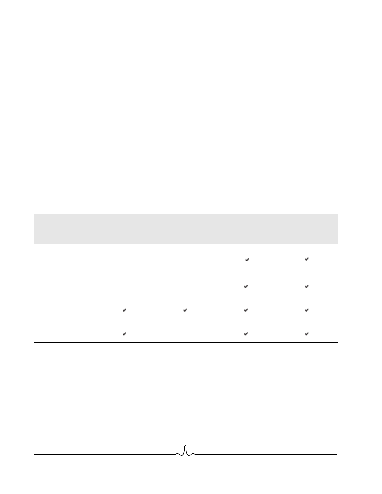
Smart Load Balancing™ (SLB) is a protocol-specific scheme. The level of support for IP, IPX, and NetBEUI protocols is listed
in Table 1.
Broadcom Corporation
Page 12 Load Balancing and Fault Tolerance Document ENGSRVT52-CDUM100-R

User Guide NetXtreme II
January 2010
NOTE: IPv6 is supported for addressing, but is not supported for load balancing.
Table 1: Smart Load Balancing
Operating System Failover/Fallback — All Broadcom Failover/Fallback — Multivendor
Protocol IP IPv6 IPX NetBEUI IP IPv6 IPX NetBEUI
Windows 2000 Server Y N/S Y Y Y N/S N N
Windows Server 2003 SP2 Y N/S Y N/S Y N/S N N/S
Windows Server 2008 Y N/S Y N/S Y N/S N N/S
Windows Server 2008 R2 Y N/S Y N/S Y N/S N N/S
Operating System Load Balance — All Broadcom Load Balance — Multivendor
Protocol IP IPv6 IPX NetBEUI IP IPv6 IPX NetBEUI
Windows 2000 Server Y N/S Y N Y N/S N N
Windows Server 2003 SP2 Y N/S Y N/S Y N/S N N/S
Windows Server 2008 Y N/S Y N/S Y N/S N N/S
Windows Server 2008 R2 Y N/S Y N/S Y N/S N N/S
Legend Y = yes
N = no
N/S = not supported
The Smart Load Balancing type of team works with all Ethernet switches without having to configure the switch ports to any
special trunking mode. Only IP traffic is load-balanced in both inbound and outbound directions. IPX traffic is load-balanced
in the outbound direction only. Other protocol packets are sent and received through one primary interface only. Failover for
non-IP traffic is supported only for Broadcom network adapters. The Generic Trunking type of team requires the Ethernet
switch to support some form of port trunking mode (for example, Cisco's Gigabit EtherChannel or other switch vendor's Link
Aggregation mode). The Generic Trunking type of team is protocol-independent, and all traffic should be load-balanced and
fault-tolerant.
NOTE: If you do not enable LiveLink™ when configuring teams, disabling Spanning Tree Protocol (STP) or
enabling Port Fast at the switch is recommended. This minimizes the downtime due to the spanning tree loop
determination when failing over. LiveLink mitigates such issues.
TEAMING AND LARGE SEND OFFLOAD/CHECKSUM OFFLOAD SUPPORT
Large Send Offload (LSO) and Checksum Offload are enabled for a team only when all of the members support and are
configured for the feature.
Broadcom Corporation
Document ENGSRVT52-CDUM100-R Load Balancing and Fault Tolerance Page 13

NetXtreme II User Guide
January 2010
Broadcom Gigabit Ethernet Teaming Services:
Broadcom NetXtreme II™ Network Adapter User
Guide
• Executive Summary
• Teaming Mechanisms
• Teaming and Other Advanced Networking Properties
• General Network Considerations
• Application Considerations
• Troubleshooting Teaming Problems
• Frequently Asked Questions
• Appendix A: Event Log Messages
EXECUTIVE SUMMARY
•Glossary
• Teaming Concepts
• Software Components
• Hardware Requirements
• Teaming Support by Processor
• Configuring Teaming
• Supported Features by Team Type
• Selecting a Team Type
This section describes the technology and implementation considerations when working with the network teaming services
offered by the Broadcom software shipped with servers and storage products. The goal of Broadcom teaming services is to
provide fault tolerance and link aggregation across a team of two or more adapters. The information in this document is
provided to assist IT professionals during the deployment and troubleshooting of system applications that require network
fault tolerance and load balancing.
Broadcom Corporation
Page 14 Broadcom Gigabit Ethernet Teaming Services: Broadcom NetXtreme II™ Network Adapter User Guide

User Guide NetXtreme II
January 2010
GLOSSARY
Table 1: Glossary
Item Definition
ARP Address Resolution Protocol
BACS Broadcom Advanced Control Suite
BASP Broadcom Advanced Server Program (intermediate driver)
DNS domain name service
G-ARP Gratuitous Address Resolution Protocol
Generic Trunking (FEC/GEC)/802.3ad-Draft Static Switch-dependent load balancing and failover type of team
HSRP Hot Standby Router Protocol
ICMP Internet Control Message Protocol
IGMP Internet Group Management Protocol
IP Internet Protocol
IPv6 Version 6 of the IP Protocol
iSCSI Internet Small Computer Systems Interface
L2 Layer 2. Used to describe network traffic that is not
L4 Layer 4. Used to describe network traffic that is heavily
LACP Link Aggregation Control Protocol
Link Aggregation (802.3ad) Switch-dependent load balancing and failover type of team
LOM LAN on Motherboard
MAC media access control
NDIS Network Driver Interface Specification
NLB Network Load Balancing (Microsoft)
PXE Preboot Execution Environment
RAID redundant array of inexpensive disks
Smart Load Balancing™ and Failover Switch-independent failover type of team in which the
Smart Load Balancing (SLB) Switch-independent load balancing and failover type of
TCP Transmission Control Protocol
TOE TCP Offload Engine. This is the hardware that is capable of
UDP User Datagram Protocol
in which the intermediate driver manages outgoing traffic
and the switch manages incoming traffic.
offloaded, and where hardware only performs Layer 2
operations on the traffic. Layer 3 (IP) and Layer 4 (TCP)
protocols are processed in software.
offloaded to the hardware, where much of the Layer 3 (IP)
and Layer 4 (TCP) processing is done in the hardware to
improve performance.
with LACP in which the intermediate driver manages
outgoing traffic and the switch manages incoming traffic.
primary team member handles all incoming and outgoing
traffic while the standby team member is idle until a failover
event (for example, loss of link occurs). The intermediate
driver (BASP) manages incoming/outgoing traffic.
team, in which the intermediate driver manages outgoing/
incoming traffic.
handling stateful fastpath offloading of TCP and IP
processing.
Broadcom Corporation
Document ENGSRVT52-CDUM100-R Executive Summary Page 15

NetXtreme II User Guide
January 2010
Table 1: Glossary (Cont.)
Item Definition
WINS Windows name service
WLBS Windows Load Balancing Service
Broadcom Corporation
Page 16 Executive Summary Document ENGSRVT52-CDUM100-R

User Guide NetXtreme II
January 2010
TEAMING CONCEPTS
• Network Addressing
• Teaming and Network Addresses
• Description of Teaming Types
• TOE Teaming
The concept of grouping multiple physical devices to provide fault tolerance and load balancing is not new. It has been
around for years. Storage devices use RAID technology to group individual hard drives. Switch ports can be grouped
together using technologies such as Cisco Gigabit EtherChannel, IEEE 802.3ad Link Aggregation, Bay Network Multilink
Trunking, and Extreme Network Load Sharing. Network interfaces on servers can be grouped together into a team of
physical ports called a virtual adapter.
Network Addressing
To understand how teaming works, it is important to understand how node communications work in an Ethernet network.
This document is based on the assumption that the reader is familiar with the basics of IP and Ethernet network
communications. The following information provides a high-level overview of the concepts of network addressing used in an
Ethernet network. Every Ethernet network interface in a host platform, such as a computer system, requires a globally unique
Layer 2 address and at least one globally unique Layer 3 address. Layer 2 is the Data Link Layer, and Layer 3 is the Network
layer as defined in the OSI model. The Layer 2 address is assigned to the hardware and is often referred to as the MAC
address or physical address. This address is pre-programmed at the factory and stored in NVRAM on a network interface
card or on the system motherboard for an embedded LAN interface. The Layer 3 addresses are referred to as the protocol
or logical address assigned to the software stack. IP and IPX are examples of Layer 3 protocols. In addition, Layer 4
(Transport Layer) uses port numbers for each network upper level protocol such as Telnet or FTP. These port numbers are
used to differentiate traffic flows across applications. Layer 4 protocols such as TCP or UDP are most commonly used in
today’s networks. The combination of the IP address and the TCP port number is called a socket.
Ethernet devices communicate with other Ethernet devices using the MAC address, not the IP address. However, most
applications work with a host name that is translated to an IP address by a Naming Service such as WINS and DNS.
Therefore, a method of identifying the MAC address assigned to the IP address is required. The Address Resolution Protocol
for an IP network provides this mechanism. For IPX, the MAC address is part of the network address and ARP is not
required. ARP is implemented using an ARP Request and ARP Reply frame. ARP Requests are typically sent to a broadcast
address while the ARP Reply is typically sent as unicast traffic. A unicast address corresponds to a single MAC address or
a single IP address. A broadcast address is sent to all devices on a network.
Teaming and Network Addresses
A team of adapters function as a single virtual network interface and does not appear any different to other network devices
than a non-teamed adapter. A virtual network adapter advertises a single Layer 2 and one or more Layer 3 addresses. When
the teaming driver initializes, it selects one MAC address from one of the physical adapters that make up the team to be the
Team MAC address. This address is typically taken from the first adapter that gets initialized by the driver. When the system
hosting the team receives an ARP request, it selects one MAC address from among the physical adapters in the team to
use as the source MAC address in the ARP Reply. In Windows operating systems, the IPCONFIG /all command shows the
IP and MAC address of the virtual adapter and not the individual physical adapters. The protocol IP address is assigned to
the virtual network interface and not to the individual physical adapters.
For switch-independent teaming modes, all physical adapters that make up a virtual adapter must use the unique MAC
address assigned to them when transmitting data. That is, the frames that are sent by each of the physical adapters in the
Broadcom Corporation
Document ENGSRVT52-CDUM100-R Executive Summary Page 17
NetXtreme II User Guide
January 2010
team must use a unique MAC address to be IEEE compliant. It is important to note that ARP cache entries are not learned
from received frames, but only from ARP requests and ARP replies.
Description of Teaming Types
• Smart Load Balancing and Failover
• Generic Trunking
• Link Aggregation (IEEE 802.3ad LACP)
• SLB (Auto-Fallback Disable)
There are three methods for classifying the supported teaming types:
• One is based on whether the switch port configuration must also match the adapter teaming type.
• The second is based on the functionality of the team, whether it supports load balancing and failover or just failover.
• The third is based on whether the Link Aggregation Control Protocol is used or not.
Table 2 shows a summary of the teaming types and their classification.
Table 2: Available Teaming Types
Link Aggregation
Control Protocol
Support Required on
the Switch
Load Balancing Failover
Teaming Type
Smart Load Balancing
and Failover (with two
to eight load balance
team members)
SLB (Auto-Fallback
Disable)
Link Aggregation
(802.3ad)
Generic Trunking
(FEC/GEC)/802.3adDraft Static
Switch-Dependent
(Switch must support
specific type of team)
Smart Load Balancing and Failover
The Smart Load Balancing™ and Failover type of team provides both load balancing and failover when configured for load
balancing, and only failover when configured for fault tolerance. This type of team works with any Ethernet switch and
requires no trunking configuration on the switch. The team advertises multiple MAC addresses and one or more IP
addresses (when using secondary IP addresses). The team MAC address is selected from the list of load balance members.
When the system receives an ARP request, the software-networking stack will always send an ARP Reply with the team
MAC address. To begin the load balancing process, the teaming driver will modify this ARP Reply by changing the source
MAC address to match one of the physical adapters.
Broadcom Corporation
Page 18 Executive Summary Document ENGSRVT52-CDUM100-R

User Guide NetXtreme II
January 2010
Smart Load Balancing enables both transmit and receive load balancing based on the Layer 3/Layer 4 IP address and TCP/
UDP port number. In other words, the load balancing is not done at a byte or frame level but on a TCP/UDP session basis.
This methodology is required to maintain in-order delivery of frames that belong to the same socket conversation. Load
balancing is supported on 2 to 8 ports. These ports can include any combination of add-in adapters and LAN on Motherboard
(LOM) devices. Transmit load balancing is achieved by creating a hashing table using the source and destination IP
addresses and TCP/UDP port numbers.The same combination of source and destination IP addresses and TCP/UDP port
numbers will generally yield the same hash index and therefore point to the same port in the team. When a port is selected
to carry all the frames of a given socket, the unique MAC address of the physical adapter is included in the frame, and not
the team MAC address. This is required to comply with the IEEE 802.3 standard. If two adapters transmit using the same
MAC address, then a duplicate MAC address situation would occur that the switch could not handle.
Receive load balancing is achieved through an intermediate driver by sending gratuitous ARPs on a client-by-client basis
using the unicast address of each client as the destination address of the ARP request (also known as a directed ARP). This
is considered client load balancing and not traffic load balancing. When the intermediate driver detects a significant load
imbalance between the physical adapters in an SLB team, it will generate G-ARPs in an effort to redistribute incoming
frames. The intermediate driver (BASP) does not answer ARP requests; only the software protocol stack provides the
required ARP Reply. It is important to understand that receive load balancing is a function of the number of clients that are
connecting to the system through the team interface.
SLB receive load balancing attempts to load balance incoming traffic for client machines across physical ports in the team.
It uses a modified gratuitous ARP to advertise a different MAC address for the team IP Address in the sender physical and
protocol address. This G-ARP is unicast with the MAC and IP Address of a client machine in the target physical and protocol
address respectively. This causes the target client to update its ARP cache with a new MAC address map to the team IP
address. G-ARPs are not broadcast because this would cause all clients to send their traffic to the same port. As a result,
the benefits achieved through client load balancing would be eliminated, and could cause out-of-order frame delivery. This
receive load balancing scheme works as long as all clients and the teamed system are on the same subnet or broadcast
domain.
When the clients and the system are on different subnets, and incoming traffic has to traverse a router, the received traffic
destined for the system is not load balanced. The physical adapter that the intermediate driver has selected to carry the IP
flow carries all of the traffic. When the router sends a frame to the team IP address, it broadcasts an ARP request (if not in
the ARP cache). The server software stack generates an ARP reply with the team MAC address, but the intermediate driver
modifies the ARP reply and sends it over a particular physical adapter, establishing the flow for that session.
The reason is that ARP is not a routable protocol. It does not have an IP header and therefore, is not sent to the router or
default gateway. ARP is only a local subnet protocol. In addition, since the G-ARP is not a broadcast packet, the router will
not process it and will not update its own ARP cache.
The only way that the router would process an ARP that is intended for another network device is if it has Proxy ARP enabled
and the host has no default gateway. This is very rare and not recommended for most applications.
Transmit traffic through a router will be load balanced as transmit load balancing is based on the source and destination IP
address and TCP/UDP port number. Since routers do not alter the source and destination IP address, the load balancing
algorithm works as intended.
Configuring routers for Hot Standby Routing Protocol (HSRP) does not allow for receive load balancing to occur in the
adapter team. In general, HSRP allows for two routers to act as one router, advertising a virtual IP and virtual MAC address.
One physical router is the active interface while the other is standby. Although HSRP can also load share nodes (using
different default gateways on the host nodes) across multiple routers in HSRP groups, it always points to the primary MAC
address of the team.
Broadcom Corporation
Document ENGSRVT52-CDUM100-R Executive Summary Page 19

NetXtreme II User Guide
January 2010
Generic Trunking
Generic Trunking is a switch-assisted teaming mode and requires configuring ports at both ends of the link: server interfaces
and switch ports. This is often referred to as Cisco Fast EtherChannel or Gigabit EtherChannel. In addition, generic trunking
supports similar implementations by other switch OEMs such as Extreme Networks Load Sharing and Bay Networks or IEEE
802.3ad Link Aggregation static mode. In this mode, the team advertises one MAC Address and one IP Address when the
protocol stack responds to ARP Requests. In addition, each physical adapter in the team uses the same team MAC address
when transmitting frames. This is possible since the switch at the other end of the link is aware of the teaming mode and will
handle the use of a single MAC address by every port in the team. The forwarding table in the switch will reflect the trunk as
a single virtual port.
In this teaming mode, the intermediate driver controls load balancing and failover for outgoing traffic only, while incoming
traffic is controlled by the switch firmware and hardware. As is the case for Smart Load Balancing, the BASP intermediate
driver uses the IP/TCP/UDP source and destination addresses to load balance the transmit traffic from the server. Most
switches implement an XOR hashing of the source and destination MAC address.
NOTE: Generic Trunking is not supported on iSCSI offload adapters.
Link Aggregation (IEEE 802.3ad LACP)
Link Aggregation is similar to Generic Trunking except that it uses the Link Aggregation Control Protocol to negotiate the
ports that will make up the team. LACP must be enabled at both ends of the link for the team to be operational. If LACP is
not available at both ends of the link, 802.3ad provides a manual aggregation that only requires both ends of the link to be
in a link up state. Because manual aggregation provides for the activation of a member link without performing the LACP
message exchanges, it should not be considered as reliable and robust as an LACP negotiated link. LACP automatically
determines which member links can be aggregated and then aggregates them. It provides for the controlled addition and
removal of physical links for the link aggregation so that no frames are lost or duplicated. The removal of aggregate link
members is provided by the marker protocol that can be optionally enabled for Link Aggregation Control Protocol (LACP)
enabled aggregate links.
The Link Aggregation group advertises a single MAC address for all the ports in the trunk. The MAC address of the
Aggregator can be the MAC addresses of one of the MACs that make up the group. LACP and marker protocols use a
multicast destination address.
The Link Aggregation control function determines which links may be aggregated and then binds the ports to an Aggregator
function in the system and monitors conditions to determine if a change in the aggregation group is required. Link
aggregation combines the individual capacity of multiple links to form a high performance virtual link. The failure or
replacement of a link in an LACP trunk will not cause loss of connectivity. The traffic will simply be failed over to the remaining
links in the trunk.
SLB (Auto-Fallback Disable)
This type of team is identical to the Smart Load Balance and Failover type of team, with the following exception—when the
standby member is active, if a primary member comes back on line, the team continues using the standby member rather
than switching back to the primary member. This type of team is supported only for situations in which the network cable is
disconnected and reconnected to the network adapter. It is not supported for situations in which the adapter is removed/
installed through Device Manager or Hot-Plug PCI.
If any primary adapter assigned to a team is disabled, the team functions as a Smart Load Balancing and Failover type of
team in which auto-fallback occurs.
Broadcom Corporation
Page 20 Executive Summary Document ENGSRVT52-CDUM100-R

User Guide NetXtreme II
January 2010
TOE Teaming
All four basic teaming modes support failover of traffic from a failed adapter to other working adapters. All four teaming
modes also support bidirectional load-balancing of TCP/IP traffic. A primary difference between the modes is that the SLB
modes use a Broadcom proprietary algorithm to control how both inbound and outbound traffic is balanced across the
network interfaces in the team. This has several advantages. First, with Generic Trunking or Link Aggregation modes, the
team of network adapters must be connected to a switch that is specifically configured to support that particular mode of
teaming. Since there is a dependency between the switch and the host team configuration when Generic Trunking or Link
Aggregation is used, it can often lead to configuration difficulties, because both ends must be configured correctly and be
synchronized. Second, with Generic Trunking or Link Aggregation modes, the switch decides how inbound traffic to the team
is balanced across the adapters, while BASP only controls the balancing of outbound traffic. This is problematic for TOE
environments, because in order for TOE to work, state information about a given TCP connection is stored in the hardware
on a given offloaded adapter, but it is not stored in the hardware on every member of the team. So teaming and TOE cannot
co-exist if the teaming software cannot steer incoming TCP/IP traffic to the adapter that contains and updates the state
information for a given TCP connection.
Because Broadcom’s SLB modes can control how both outbound and inbound packets are balanced across the adapters,
the SLB modes are capable of ensuring that all offloaded TCP traffic for a given TCP connection goes in and out of a
particular adapter. This architectural feature allows the SLB modes to also support load-balancing on adapters that have
TOE enabled, since BASP is able to steer traffic on a particular TCP connection to the adapter hardware that contains
offloaded state information for that TCP connection. BASP can simultaneously use TCP offload in conjunction with the SLB
modes of teaming. Other teaming modes (Generic Trunking or Link Aggregation) can still be used on TOE capable devices,
but if those other modes are enabled the TOE feature is disabled.
Since the TOE offloaded state is stored in only one member of a team, it might not be intuitive as to how BASP can support
failover on TOE teams. When a TOE connection has been offloaded to a given adapter, and if that network interface fails in
some way (that is, it loses its network link due to a cable disconnection), then BASP will detect the error and force an upload
of the offloaded TCP state for each previously offloaded TCP connection on that adapter to the host. Once all of the
previously offloaded state has been uploaded, BASP will rebalance the recently uploaded TCP connections and offload
those connections evenly to the remaining members of the team. Basically, if there is a failure on a TOE-enabled adapter,
any TCP connections that had been offloaded to that adapter are migrated to the remaining nonfailed members in the team.
For Broadcom NetXtreme II adapters, there are no specific setup requirements in order for TCP Offload Engine (TOE) to
work with BASP. Once the individual adapters are configured to enable TOE, they can be added to a team and the offload
is transparent to BASP. For information on configuring TOE, see Viewing Resource Reservations.
Limitations of Teaming with Offloading
• TOE is enabled for a team only when all of the members support and are configured for TOE.
• TOE is only supported on SLB-type teams.
• Each virtual BASP device advertises 1024 offload connections. If the number of virtual BASP devices in a team
exceeds the number of active physical members, the maximum offload connections for each virtual device may be
lower.
SOFTWARE COMPONENTS
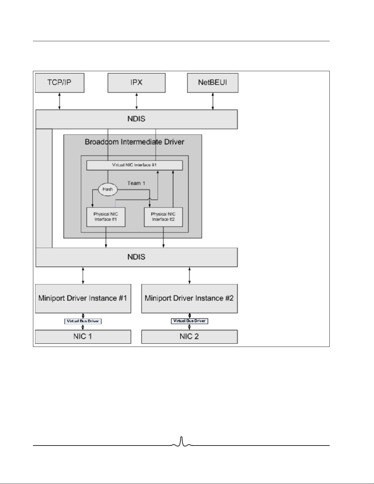
Teaming is implemented via an NDIS intermediate driver in the Windows Operating System environment. This software
component works with the miniport driver, the NDIS layer, and the protocol stack to enable the teaming architecture (see
Figure 2). The miniport driver controls the host LAN controller directly to enable functions such as sends, receives, and
interrupt processing. The intermediate driver fits between the miniport driver and the protocol layer multiplexing several
miniport driver instances, and creating a virtual adapter that looks like a single adapter to the NDIS layer. NDIS provides a
Broadcom Corporation
Document ENGSRVT52-CDUM100-R Executive Summary Page 21

NetXtreme II User Guide
January 2010
set of library functions to enable the communications between either miniport drivers or intermediate drivers and the protocol
stack. The protocol stack implements IP, IPX and ARP. A protocol address such as an IP address is assigned to each
miniport device instance, but when an Intermediate driver is installed, the protocol address is assigned to the virtual team
adapter and not to the individual miniport devices that make up the team.
The Broadcom supplied teaming support is provided by three individual software components that work together and are
supported as a package. When one component is upgraded, all the other components must be upgraded to the supported
versions. Table 3 describes the four software components and their associated files for supported operating systems.
Table 3: Broadcom Teaming Software Component
Software
Component
Miniport Driver Broadcom Base Driver Windows 2000 Server (NDIS 5.0) bxnd50x.sys
Intermediate
Driver
Configuration
User Interface
Broadcom Name Network Adapter/Operating System
Virtual Bus Driver
(VBD)
Broadcom Advanced
Server Program
(BASP)
Broadcom Advanced
Control Suite 3
(BACS)
BCM5706, BCM5708, BCM5709 32-bit bxvbdx.sys
BCM5706, BCM5708, BCM5709 64-bit bxvbda.sys
BCM57710, BCM57711 32-bit evbdx.sys
BCM57710, BCM57711 64-bit evbda.sys
Windows Server 2003 (NDIS 5.1) 32-bit bxnd51x.sys
Windows Server 2003 (NDIS 5.1) 64-bit bxnd51a.sys
Windows Server 2003 (NDIS 5.2)
Driver supports Layer 4
Windows Server 2003 (NDIS 5.2)
Driver supports Layer 4
Windows Server 2008 (NDIS 6.0) 32-bit bxnd60x.sys
Windows Server 2008 (NDIS 6.0) 64-bit bxnd60a.sys
Windows Server 2008 R2 (NDIS 6.0) 64-bit bxnd60a.sys
Windows 2000 Server 32-bit baspw2k.sys
Windows Server 2003 32-bit baspxp32.sys
Windows Server 2003 64-bit basamd64.sys
Windows Server 2008 32-bit, 64-bit basp.sys
Windows Server 2008 R2 64-bit basp.sys
––bacs.exe
System
Architecture
32-bit bxnd52x.sys
64-bit bxnd52a.sys
Windows File
Name
Broadcom Corporation
Page 22 Executive Summary Document ENGSRVT52-CDUM100-R

User Guide NetXtreme II
January 2010
HARDWARE REQUIREMENTS
• Repeater Hub
• Switching Hub
•Router
The various teaming modes described in this document place certain restrictions on the networking equipment used to
connect clients to teamed systems. Each type of network interconnect technology has an effect on teaming as described in
the following sections.
Repeater Hub
A Repeater Hub allows a network administrator to extend an Ethernet network beyond the limits of an individual segment.
The repeater regenerates the input signal received on one port onto all other connected ports, forming a single collision
domain. This means that when a station attached to a repeater sends an Ethernet frame to another station, every station
within the same collision domain will also receive that message. If two stations begin transmitting at the same time, a collision
occurs, and each transmitting station must retransmit its data after waiting a random amount of time.
The use of a repeater requires that each station participating within the collision domain operate in half-duplex mode.
Although half-duplex mode is supported for Gigabit Ethernet adapters in the IEEE 802.3 specification, half-duplex mode is
not supported by the majority of Gigabit Ethernet adapter manufacturers. Therefore, half-duplex mode is not considered
here.
Teaming across hubs is supported for troubleshooting purposes (such as connecting a network analyzer) for SLB teams
only.
Switching Hub
Unlike a repeater hub, a switching hub (or more simply a switch) allows an Ethernet network to be broken into multiple
collision domains. The switch is responsible for forwarding Ethernet packets between hosts based solely on Ethernet MAC
addresses. A physical network adapter that is attached to a switch may operate in half-duplex or full-duplex mode.
To support Generic Trunking and 802.3ad Link Aggregation, a switch must specifically support such functionality. If the
switch does not support these protocols, it may still be used for Smart Load Balancing.
NOTE: All modes of network teaming are supported across switches when operating as a stackable switch.
Router
A router is designed to route network traffic based on Layer 3 or higher protocols, although it often also works as a Layer 2
device with switching capabilities. The teaming of ports connected directly to a router is not supported.
Broadcom Corporation
Document ENGSRVT52-CDUM100-R Executive Summary Page 23

NetXtreme II User Guide
January 2010
TEAMING SUPPORT BY PROCESSOR
All team types are supported by the IA-32, AMD-64, and EM64T processors.
CONFIGURING TEAMING
The Broadcom Advanced Control Suite 3 utility is used to configure teaming in the supported operating system
environments.
The Broadcom Advanced Control Suite 3 (BACS) utility is designed to run on 32-bit and 64-bit Windows family of operating
systems. BACS 3 is used to configure load balancing and fault tolerance teaming, and VLANs. In addition, it displays the
MAC address, driver version, and status information about each network adapter. BACS 3 also includes a number of
diagnostics tools such as hardware diagnostics, cable testing, and a network topology test.
SUPPORTED FEATURES BY TEAM TYPE
Table 4 provides a feature comparison across the team types. Use this table to determine the best type of team for your
application. The teaming software supports up to eight ports in a single team and up to four teams in a single system. The
four teams can be any combination of the supported teaming types, but each team must be on a separate network or subnet.
Table 4: Comparison of Team Types
Type of Team Fault Tolerance Load Balancing
Function
Number of ports per
team (same
broadcast domain)
Number of teams 4 4 4 4
Adapter fault
tolerance
Switch link fault
tolerance (same
broadcast domain)
TX load balancing No Yes Yes Yes
RX load balancing No Yes Yes (performed by the
Requires compatible
switch
Heartbeats to check
connectivity
Mixed media
(adapters with
different media)
SLB with Standby
2–8 2–8 2–8 2–8
Yes Yes Yes Yes
Yes Yes Switch-dependent Switch-dependent
No No Yes Yes
No No No No
Yes Yes Yes (switch-
a
SLB Generic Trunking Link Aggregation
Switch-Dependent
Static Trunking
switch)
dependent)
Switch-Independent
Dynamic Link
Aggregation
(IEEE 802.3ad)
Yes (performed by the
switch)
Yes
Broadcom Corporation
Page 24 Executive Summary Document ENGSRVT52-CDUM100-R

User Guide NetXtreme II
January 2010
Table 4: Comparison of Team Types (Cont.)
Switch-Independent
Type of Team Fault Tolerance Load Balancing
Switch-Dependent
Static Trunking
Dynamic Link
Aggregation
(IEEE 802.3ad)
Function
Mixed speeds
SLB with Standby
Yes Yes No No
a
SLB Generic Trunking Link Aggregation
(adapters that do not
support a common
speed(s), but can
operate at different
speeds)
Mixed speeds
(adapters that support
Yes Yes No (must be the same
speed)
Yes
a common speed(s),
but can operate at
different speeds)
Load balances TCP/IPNo Yes Yes Yes
Mixed vendor teaming
Yes
b
Load balances non-IP No Yes (IPX outbound
Yes
b
Yes
b
Yes
Yes Yes
traffic only)
Same MAC address
No No Yes Yes
for all team members
Same IP address for
Yes Yes Yes Yes
all team members
Load balancing by IP
No Yes Yes Yes
address
Load balancing by
MAC address
Allows TOE
No Yes (used for no-IP/
Yes Yes
IPX)
Yes Yes No No
functionality to coexist when all team
members support
c
TOE
b
a
SLB with one primary and one standby member.
b
Requires at least one Broadcom adapter in the team.
c TOE functionality can only be achieved with SLB teams that consist of all Broadcom TOE-enabled adapters.
Broadcom Corporation
Document ENGSRVT52-CDUM100-R Executive Summary Page 25
NetXtreme II User Guide
January 2010
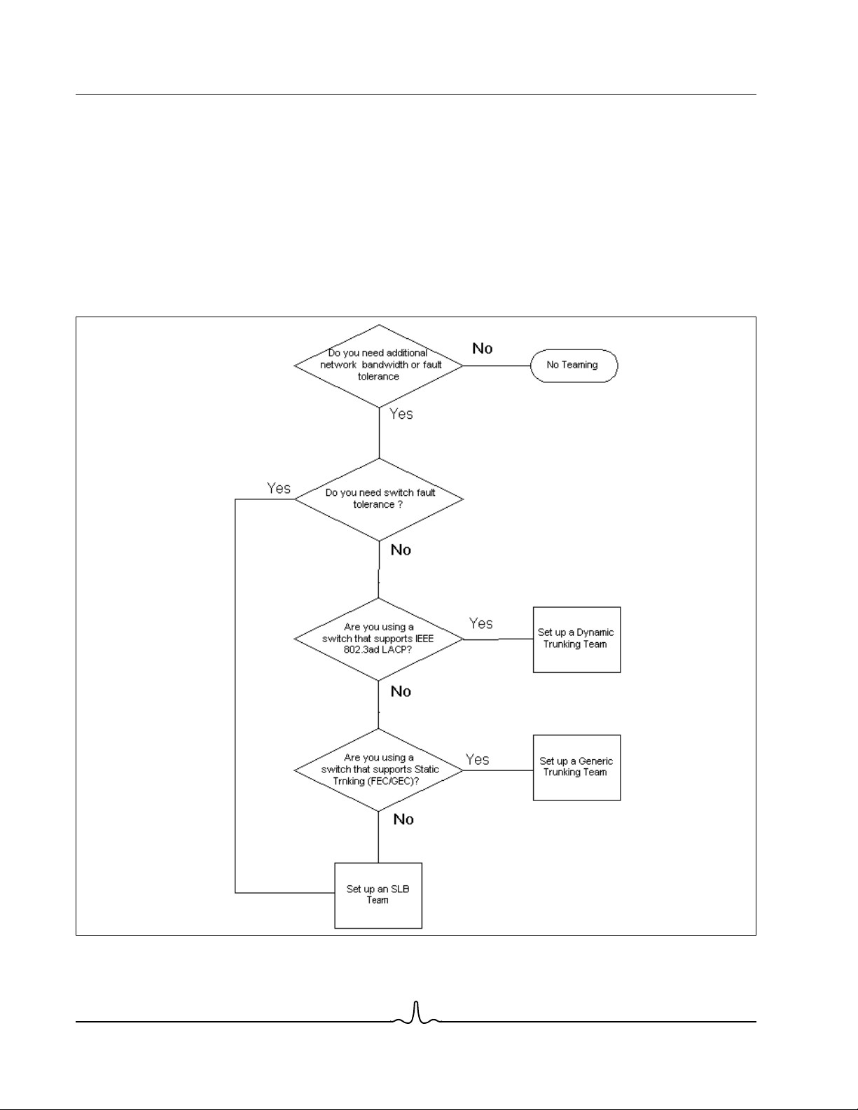
SELECTING A TEAM TYPE
The following flow chart provides the decision flow when planning for Layer 2 teaming. For TOE teaming, only Smart Load
Balancing™ and Failover type team is supported. The primary rationale for teaming is the need for additional network
bandwidth and fault tolerance. Teaming offers link aggregation and fault tolerance to meet both of these requirements.
Preference teaming should be selected in the following order: Link Aggregation as the first choice, Generic Trunking as the
second choice, and SLB teaming as the third choice when using unmanaged switches or switches that do not support the
first two options. if switch fault tolerance is a requirement, then SLB is the only choice (see Figure 1).
Figure 1: Process for Selecting a Team Type
Broadcom Corporation
Page 26 Executive Summary Document ENGSRVT52-CDUM100-R

User Guide NetXtreme II
January 2010
TEAMING MECHANISMS
• Architecture
• Types of Teams
• Attributes of the Features Associated with Each Type of Team
• Speeds Supported for Each Type of Team
ARCHITECTURE
The Broadcom Advanced Server Program is implemented as an NDIS intermediate driver (see Figure 2). It operates below
protocol stacks such as TCP/IP and IPX and appears as a virtual adapter. This virtual adapter inherits the MAC Address of
the first port initialized in the team. A Layer 3 address must also be configured for the virtual adapter. The primary function
of BASP is to balance inbound (for SLB) and outbound traffic (for all teaming modes) among the physical adapters installed
on the system selected for teaming. The inbound and outbound algorithms are independent and orthogonal to each other.
The outbound traffic for a particular session can be assigned to a given port while its corresponding inbound traffic can be
assigned to a different port.
Broadcom Corporation
Document ENGSRVT52-CDUM100-R Teaming Mechanisms Page 27
NetXtreme II User Guide
January 2010
Figure 2: Intermediate Driver
Outbound Traffic Flow
The Broadcom Intermediate Driver manages the outbound traffic flow for all teaming modes. For outbound traffic, every
packet is first classified into a flow, and then distributed to the selected physical adapter for transmission. The flow
classification involves an efficient hash computation over known protocol fields. The resulting hash value is used to index
into an Outbound Flow Hash Table.The selected Outbound Flow Hash Entry contains the index of the selected physical
adapter responsible for transmitting this flow. The source MAC address of the packets will then be modified to the MAC
address of the selected physical adapter. The modified packet is then passed to the selected physical adapter for
transmission.
Broadcom Corporation
Page 28 Teaming Mechanisms Document ENGSRVT52-CDUM100-R

User Guide NetXtreme II
January 2010
The outbound TCP and UDP packets are classified using Layer 3 and Layer 4 header information. This scheme improves
the load distributions for popular Internet protocol services using well-known ports such as HTTP and FTP. Therefore, BASP
performs load balancing on a TCP session basis and not on a packet-by-packet basis.
In the Outbound Flow Hash Entries, statistics counters are also updated after classification. The load-balancing engine uses
these counters to periodically distribute the flows across teamed ports. The outbound code path has been designed to
achieve best possible concurrency where multiple concurrent accesses to the Outbound Flow Hash Table are allowed.
For protocols other than TCP/IP, the first physical adapter will always be selected for outbound packets. The exception is
Address Resolution Protocol (ARP), which is handled differently to achieve inbound load balancing.
Inbound Traffic Flow (SLB Only)
The Broadcom intermediate driver manages the inbound traffic flow for the SLB teaming mode. Unlike outbound load
balancing, inbound load balancing can only be applied to IP addresses that are located in the same subnet as the loadbalancing server. Inbound load balancing exploits a unique characteristic of Address Resolution Protocol (RFC0826), in
which each IP host uses its own ARP cache to encapsulate the IP Datagram into an Ethernet frame. BASP carefully
manipulates the ARP response to direct each IP host to send the inbound IP packet to the desired physical adapter.
Therefore, inbound load balancing is a plan-ahead scheme based on statistical history of the inbound flows. New
connections from a client to the server will always occur over the primary physical adapter (because the ARP Reply
generated by the operating system protocol stack will always associate the logical IP address with the MAC address of the
primary physical adapter).
Like the outbound case, there is an Inbound Flow Head Hash Table. Each entry inside this table has a singly linked list and
each link (Inbound Flow Entries) represents an IP host located in the same subnet.
When an inbound IP Datagram arrives, the appropriate Inbound Flow Head Entry is located by hashing the source IP
address of the IP Datagram. Two statistics counters stored in the selected entry are also updated. These counters are used
in the same fashion as the outbound counters by the load-balancing engine periodically to reassign the flows to the physical
adapter.
On the inbound code path, the Inbound Flow Head Hash Table is also designed to allow concurrent access. The link lists of
Inbound Flow Entries are only referenced in the event of processing ARP packets and the periodic load balancing. There is
no per packet reference to the Inbound Flow Entries. Even though the link lists are not bounded; the overhead in processing
each non-ARP packet is always a constant. The processing of ARP packets, both inbound and outbound, however, depends
on the number of links inside the corresponding link list.
On the inbound processing path, filtering is also employed to prevent broadcast packets from looping back through the
system from other physical adapters.
Protocol Support
ARP and IP/TCP/UDP flows are load balanced. If the packet is an IP protocol only, such as ICMP or IGMP, then all data
flowing to a particular IP address will go out through the same physical adapter. If the packet uses TCP or UDP for the L4
protocol, then the port number is added to the hashing algorithm, so two separate L4 flows can go out through two separate
physical adapters to the same IP address.
For example, assume the client has an IP address of 10.0.0.1. All IGMP and ICMP traffic will go out the same physical
adapter because only the IP address is used for the hash. The flow would look something like this:
IGMP ------> PhysAdapter1 ------> 10.0.0.1
Broadcom Corporation
Document ENGSRVT52-CDUM100-R Teaming Mechanisms Page 29

NetXtreme II User Guide
January 2010
ICMP ------> PhysAdapter1 ------> 10.0.0.1
If the server also sends an TCP and UDP flow to the same 10.0.0.1 address, they can be on the same physical adapter as
IGMP and ICMP, or on completely different physical adapters from ICMP and IGMP. The stream may look like this:
IGMP ------> PhysAdapter1 ------> 10.0.0.1
ICMP ------> PhysAdapter1 ------> 10.0.0.1
TCP------> PhysAdapter1 ------> 10.0.0.1
UDP------> PhysAdatper1 ------> 10.0.0.1
Or the streams may look like this:
IGMP ------> PhysAdapter1 ------> 10.0.0.1
ICMP ------> PhysAdapter1 ------> 10.0.0.1
TCP------> PhysAdapter2 ------> 10.0.0.1
UDP------> PhysAdatper3 ------> 10.0.0.1
The actual assignment between adapters may change over time, but any protocol that is not TCP/UDP based goes over the
same physical adapter because only the IP address is used in the hash.
Performance
Modern network interface cards provide many hardware features that reduce CPU utilization by offloading certain CPU
intensive operations (see Teaming and Other Advanced Networking Properties). In contrast, the BASP intermediate driver
is a purely software function that must examine every packet received from the protocol stacks and react to its contents
before sending it out through a particular physical interface. Though the BASP driver can process each outgoing packet in
near constant time, some applications that may already be CPU bound may suffer if operated over a teamed interface. Such
an application may be better suited to take advantage of the failover capabilities of the intermediate driver rather than the
load balancing features, or it may operate more efficiently over a single physical adapter that provides a particular hardware
feature such as Large Send Offload.
TYPES OF TEAMS
Switch-Independent
The Broadcom Smart Load Balancing type of team allows two to eight physical adapters to operate as a single virtual
adapter. The greatest benefit of the SLB type of team is that it operates on any IEEE compliant switch and requires no special
configuration.
Smart Load Balancing and Failover
SLB provides for switch-independent, bidirectional, fault-tolerant teaming and load balancing. Switch independence implies
that there is no specific support for this function required in the switch, allowing SLB to be compatible with all switches. Under
SLB, all adapters in the team have separate MAC addresses. The load-balancing algorithm operates on Layer 3 addresses
of the source and destination nodes, which enables SLB to load balance both incoming and outgoing traffic.
Broadcom Corporation
Page 30 Teaming Mechanisms Document ENGSRVT52-CDUM100-R
Loading...