


 Loading...
Cisco IE 3010 Switch Hardware Installation
Guide
Revised October 12, 2012
Americas Headquarters
Cisco Systems, Inc. 170 West Tasman Drive
San Jose, CA 95134-1706 USA http://www.cisco.com Tel: 408 526-4000
800 553-NETS (6387) Fax: 408 527-0883
Text Part Number: 78-19581-02
THE SPECIFICATIONS AND INFORMATION REGARDING THE PRODUCTS IN THIS MANUAL ARE SUBJECT TO CHANGE WITHOUT NOTICE. ALL STATEMENTS, INFORMATION, AND RECOMMENDATIONS IN THIS MANUAL ARE BELIEVED TO BE ACCURATE BUT ARE PRESENTED WITHOUT WARRANTY OF ANY KIND, EXPRESS OR IMPLIED. USERS MUST TAKE FULL RESPONSIBILITY FOR THEIR APPLICATION OF ANY PRODUCTS.
THE SOFTWARE LICENSE AND LIMITED WARRANTY FOR THE ACCOMPANYING PRODUCT ARE SET FORTH IN THE INFORMATION PACKET THAT SHIPPED WITH THE PRODUCT AND ARE INCORPORATED HEREIN BY THIS REFERENCE. IF YOU ARE UNABLE TO LOCATE THE SOFTWARE LICENSE OR LIMITED WARRANTY, CONTACT YOUR CISCO REPRESENTATIVE FOR A COPY.
The following information is for FCC compliance of Class A devices: This equipment has been tested and found to comply with the limits for a Class A digital device, pursuant to part 15 of the FCC rules. These limits are designed to provide reasonable protection against harmful interference when the equipment is operated in a commercial environment. This equipment generates, uses, and can radiate radio-frequency energy and, if not installed and used in accordance with the instruction manual, may cause harmful interference to radio communications. Operation of this equipment in a residential area is likely to cause harmful interference, in which case users will be required to correct the interference at their own expense.
The following information is for FCC compliance of Class B devices: This equipment has been tested and found to comply with the limits for a Class B digital device, pursuant to part 15 of the FCC rules. These limits are designed to provide reasonable protection against harmful interference in a residential installation. This equipment generates, uses and can radiate radio frequency energy and, if not installed and used in accordance with the instructions, may cause harmful interference to radio communications.
However, there is no guarantee that interference will not occur in a particular installation. If the equipment causes interference to radio or television reception, which can be determined by turning the equipment off and on, users are encouraged to try to correct the interference by using one or more of the following measures:
•Reorient or relocate the receiving antenna.
•Increase the separation between the equipment and receiver.
•Connect the equipment into an outlet on a circuit different from that to which the receiver is connected.
•Consult the dealer or an experienced radio/TV technician for help.
Modifications to this product not authorized by Cisco could void the FCC approval and negate your authority to operate the product.
The Cisco implementation of TCP header compression is an adaptation of a program developed by the University of California, Berkeley (UCB) as part of UCB’s public domain version of the UNIX operating system. All rights reserved. Copyright © 1981, Regents of the University of California.
NOTWITHSTANDING ANY OTHER WARRANTY HEREIN, ALL DOCUMENT FILES AND SOFTWARE OF THESE SUPPLIERS ARE PROVIDED “AS IS” WITH ALL FAULTS. CISCO AND THE ABOVE-NAMED SUPPLIERS DISCLAIM ALL WARRANTIES, EXPRESSED OR IMPLIED, INCLUDING, WITHOUT LIMITATION, THOSE OF MERCHANTABILITY, FITNESS FOR A PARTICULAR PURPOSE AND NONINFRINGEMENT OR ARISING FROM A COURSE OF DEALING, USAGE, OR TRADE PRACTICE.
Cisco and the Cisco logo are trademarks or registered trademarks of Cisco and/or its affiliates in the U.S. and other countries. To view a list of Cisco trademarks, go to this URL: www.cisco.com/go/trademarks. Third-party trademarks mentioned are the property of their respective owners. The use of the word partner does not imply a partnership relationship between Cisco and any other company. (1110R)
Any Internet Protocol (IP) addresses used in this document are not intended to be actual addresses. Any examples, command display output, and figures included in the document are shown for illustrative purposes only. Any use of actual IP addresses in illustrative content is unintentional and coincidental.
Cisco IE 3010 Switch Hardware Installation Guide
© 2010-2012 Cisco Systems, Inc. All rights reserved.

C O N T E N T S
|
Preface vii |
|
|
Related Publications i-viii |
|
|
Obtaining Documentation and Submitting a Service Request i-viii |
|
|
Product Overview |
|
C H A P T E R 1 |
1-1 |
|
|
Switch Models |
1-1 |
|
Cable Side 1-2 |
|
10/100 Fast Ethernet Ports |
1-3 |
|
|||
PoE Ports 1-3 |
|
|
|
|
|
Dual-Purpose Ports |
1-4 |
|
|
||
SFP Modules |
1-5 |
|
|
|
|
SFP Module Patch Cable |
1-6 |
|
|||
Power-Input Terminal |
1-6 |
|
|
||
Alarm Ports |
1-6 |
|
|
|
|
Alarm Input |
1-7 |
|
|
|
|
Alarm Output |
1-7 |
|
|
|
|
Management Ports |
1-7 |
|
|
||
LEDs 1-8 |
|
|
|
|
|
Switch Panel LEDs |
1-8 |
|
|
||
System LED |
1-9 |
|
|
|
|
Power-Supply Module LEDs |
1-9 |
||||
Alarm LEDs |
1-9 |
|
|
|
|
Console LEDs |
1-10 |
|
|
||
Port LEDs |
1-10 |
|
|
|
|
PoE LED |
1-11 |
|
|
|
|
Dual-Purpose Port LEDs |
1-11 |
|
|||
SD Flash Memory Card LED |
1-11 |
||||
SD Flash Memory Card |
1-11 |
|
|||
Power-Supply Side |
1-12 |
|
|
|
|
Power-Supply Side LEDs |
1-13 |
|
|||
Power Supply Features |
1-14 |
|
|||
Management Options |
1-14 |
|
|
|
|
Network Configurations |
1-14 |
|
|||
Cisco IE 3010 Switch Hardware Installation Guide
|
78-19581-02 |
iii |
|

Contents
C H A P T E R 2 |
Switch Installation 2-1 |
|
|
Warnings 2-1 |
|
|
Installation Guidelines |
2-3 |
|
Verifying Switch Operation 2-3 |
|
|
Installing the Switch |
2-4 |
|
Rack-Mounting 2-4 |
|
|
|
|
|
|
|
|
Attaching Brackets for 19-Inch Racks |
2-5 |
|
|
||||
|
Attaching Brackets for 19-Inch Racks for IP-30 Compliance (Optional) 2-6 |
|||||||
|
Attaching Brackets for 23-Inch Racks |
2-12 |
|
|
||||
|
Attaching Brackets for ETSI Racks |
2-13 |
|
|
||||
|
Rack-Mounting the Switch |
2-14 |
|
|
|
|||
|
Wall-Mounting 2-15 |
|
|
|
|
|
|
|
|
Attaching Brackets |
2-16 |
|
|
|
|
|
|
|
Attaching Brackets for IP-30 Compliance (Optional) |
2-16 |
||||||
|
Wall-Mounting the Switch |
2-18 |
|
|
|
|||
|
Installing and Removing SFP Modules |
2-20 |
|
|
|
|||
|
Installing SFP Modules |
2-20 |
|
|
|
|
|
|
|
Removing SFP Modules |
2-21 |
|
|
|
|
|
|
|
Inserting and Removing the SFP Module Patch Cable |
2-21 |
|
|||||
|
Removing the SFP Module Patch Cable |
2-22 |
|
|
||||
|
Replacing the SD Flash Memory Card |
2-23 |
|
|
|
|||
|
Connecting Devices to the Ethernet Ports |
2-25 |
|
|
||||
|
Connecting to the 10/100 and 10/100/1000 Ports |
2-25 |
|
|||||
|
Connecting to the 10/100 PoE Ports |
2-26 |
|
|
||||
|
Where to Go Next 2-27 |
|
|
|
|
|
|
|
|
Power Supply Installation |
|
|
|
|
|
|
|
C H A P T E R 3 |
3-1 |
|
|
|
|
|
||
|
Power-Supply Modules |
3-1 |
|
|
|
|
|
|
|
Power-Supply Module Installation 3-3 |
|
|
|
|
|||
|
Installation Guidelines |
3-3 |
|
|
|
|
|
|
|
Installing a Power-Supply Module |
3-4 |
|
|
|
|||
|
Equipment That You Need |
3-4 |
|
|
|
|
||
|
Grounding the Switch 3-4 |
|
|
|
|
|
||
|
Installing the Power-Supply Module in the Switch |
3-6 |
||||||
|
Wiring the Power Source |
3-7 |
|
|
|
|
|
|
|
Removing the Power-Supply Module |
3-12 |
|
|
|
|||
Cisco IE 3010 Switch Hardware Installation Guide
|
iv |
78-19581-02 |
|
|
|

Contents
C H A P T E R 4 |
Troubleshooting 4-1 |
|
|
|
|
|
|
Diagnosing Problems |
4-1 |
|
|
|
|
|
Switch POST Results |
4-1 |
|
|
|
|
|
Switch LEDs 4-2 |
|
|
|
|
|
|
Switch Connections |
4-2 |
|
|
|
|
|
Bad or Damaged Cable |
4-2 |
|
|
||
|
Ethernet and Fiber-Optic Cables |
4-2 |
|
|||
|
Link Status |
4-2 |
|
|
|
|
|
10/100 and 10/100/1000 Port Connections |
4-3 |
||||
|
10/100 PoE Port Connections |
4-3 |
|
|||
|
SFP Module |
4-3 |
|
|
|
|
|
Interface Settings |
4-3 |
|
|
|
|
|
Ping End Device |
4-3 |
|
|
|
|
|
Spanning Tree Loops |
4-4 |
|
|
||
|
Switch Performance |
4-4 |
|
|
|
|
|
Speed, Duplex, and Autonegotiation 4-4 |
|
||||
|
Autonegotiation and Network Interface Cards |
4-4 |
||||
|
Cabling Distance |
4-4 |
|
|
|
|
|
|
Resetting the Switch to the Factory Default Settings 4-5 |
|||||
|
|
Finding the Switch Serial Number |
4-5 |
||||
|
|
Technical Specifications |
|
|
|
||
A P P E N D I X |
A |
|
A-1 |
|
|||
|
|
Switch Specifications |
A-1 |
|
|||
|
|
Power-Supply Module Specifications A-4 |
|||||
|
|
Alarm Ratings |
A-5 |
|
|
|
|
|
|
Connector and Cable Specifications |
|
||||
A P P E N D I X |
B |
B-1 |
|||||
|
|
Connector Specifications |
B-1 |
|
|||
|
|
10/100 |
B-1 |
|
|
|
|
|
|
SFP Module Connectors B-2 |
|
||||
|
|
Dual-Purpose Ports |
|
B-3 |
|
||
|
|
Alarm Port |
B-3 |
|
|
|
|
|
|
Cables and Adapters |
B-4 |
|
|||
|
|
SFP Module Cables |
B-4 |
|
|||
|
|
Cable Pinouts |
B-6 |
|
|
||
|
|
Console Port Adapter Pinouts |
B-7 |
||||
Cisco IE 3010 Switch Hardware Installation Guide
|
78-19581-02 |
v |
|

Contents
A P P E N D I X C |
Configuring the Switch with the CLI Setup Program C-1 |
|
|
|
Accessing the CLI Through the Console Port C-1 |
|
|
|
RJ-45 Console Port |
C-1 |
|
|
USB Console Port |
C-3 |
|
|
Installing the Cisco Microsoft Windows USB Device Drivers |
C-4 |
|
|
Installing the Cisco Microsoft Windows XP USB Driver |
C-4 |
|
|
Installing the Cisco Microsoft Windows 2000 USB Driver |
C-4 |
|
|
Installing the Cisco Microsoft Windows Vista USB Driver |
C-5 |
|
|
Uninstalling the Cisco Microsoft Windows USB Drivers C-5 |
|
|
|
Uninstalling the Cisco Microsoft Windows XP and 2000 USB Driver C-5 |
||
|
Uninstalling the Cisco Microsoft Windows Vista USB Driver C-6 |
||
Entering the Initial Configuration Information C-7
IP Settings C-7
Completing the Setup Program C-7
I N D E X
Cisco IE 3010 Switch Hardware Installation Guide
|
vi |
78-19581-02 |
|
|
|

Preface
This guide describes the hardware features of the Cisco Industrial Ethernet (IE) 3010 switch. It describes the physical and performance characteristics of the switch, explains how to install it, and provides troubleshooting information.
This guide does not describe system messages that you might receive or how to configure your switch. See the switch software configuration guide, the switch command reference, and the switch system message guide on Cisco.com:
http://www.cisco.com/go/IE3010_docs
Note Means reader take note. Notes contain helpful suggestions or references to materials not contained in this manual.
Caution Means reader be careful. In this situation, you might do something that could result in equipment damage or loss of data.
Warning IMPORTANT SAFETY INSTRUCTIONS
This warning symbol means danger. You are in a situation that could cause bodily injury. Before you work on any equipment, be aware of the hazards involved with electrical circuitry and be familiar with standard practices for preventing accidents. Use the statement number provided at the end of each warning to locate its translation in the translated safety warnings that accompanied this device. Statement 1071
SAVE THESE INSTRUCTIONS
Cisco IE 3010 Switch Hardware Installation Guide
|
78-19581-02 |
vii |
|

Preface
Related Publications
The safety warnings for this product are translated into several languages in the Regulatory Compliance and Safety Information for the Cisco IE 3010 Switch that ships with the product on the documentation CD. The EMC regulatory statements are also included in that guide.
Related Publications
http://www.cisco.com/go/IE3010_docs
Note Before installing, configuring, or upgrading the switch, see the release notes on Cisco.com for the latest information.
•Release Notes for the Cisco IE 3010 Switch
•Cisco IE 3010 Switch Getting Started Guide
•Regulatory Compliance and Safety Information for the Cisco IE 3010 Switch
•Cisco IE 3010 Switch Software Configuration Guide
•Cisco IE 3010 Switch Command Reference
•Cisco IE 3010 Switch System Message Guide
Cisco SFP documents:
http://www.cisco.com/en/US/products/hw/modules/ps5455/prod_installation_guides_list.html
SFP compatibility matrix documents:
http://www.cisco.com/en/US/products/hw/modules/ps5455/products_device_support_tables_list.html
Obtaining Documentation and Submitting a Service Request
For information on obtaining documentation, submitting a service request, and gathering additional information, see the monthly What’s New in Cisco Product Documentation, which also lists all new and revised Cisco technical documentation, at:
http://www.cisco.com/en/US/docs/general/whatsnew/whatsnew.html
Subscribe to the What’s New in Cisco Product Documentation as a Really Simple Syndication (RSS) feed and set content to be delivered directly to your desktop using a reader application. The RSS feeds are a free service and Cisco currently supports RSS version 2.0.
Cisco IE 3010 Switch Hardware Installation Guide
|
viii |
78-19581-02 |
|
|
|

C H A P T E R 1
Product Overview
The Cisco IE 3010 switch provides a rugged and secure switching infrastructure for harsh environments. It is suitable for industrial Ethernet applications, including process manufacturing, intelligent transportation systems (ITSs), rail transportation, and other similar deployments.
In industrial environments, you can connect the switch to any Ethernet-enabled industrial communication devices, including programmable logic controllers (PLCs), human-machine interfaces (HMIs), drives, sensors, and input and output (IO) devices.
•Switch Models, page 1-1
•Cable Side, page 1-2
•Power-Supply Side, page 1-12
•Management Options, page 1-14
Switch Models
Table 1-1 |
Switch Models |
|
||
|
|
|
|
|
|
Model |
|
|
Description |
|
|
|
|
|
|
Cisco IE-3010-24TC |
|
24 10/100 FastEthernet ports, 2 dual-purpose ports |
|
|
|
|
|
(2 10/100/1000BASE-T copper ports and 2 SFP1 module slots), and |
|
|
|
|
2 AC and DC power-supply module slots. |
|
|
|
|
|
|
Cisco IE-3010-16S-8PC |
|
16 100BASE-FX SFP-module slots; 8 10/100 FastEthernet PoE2 ports, |
|
|
|
|
|
2 dual-purpose ports (2 10/100/1000BASE-T copper ports and 2 SFP |
|
|
|
|
module slots), and 2 AC and DC power-supply module slots. |
|
|
|
|
|
1.SFP = small form-factor pluggable.
2.PoE = Power over Ethernet.
Cisco IE 3010 Switch Hardware Installation Guide
|
78-19581-02 |
1-1 |
|
|
|
Chapter 1 Product Overview
Cable Side
Cable Side
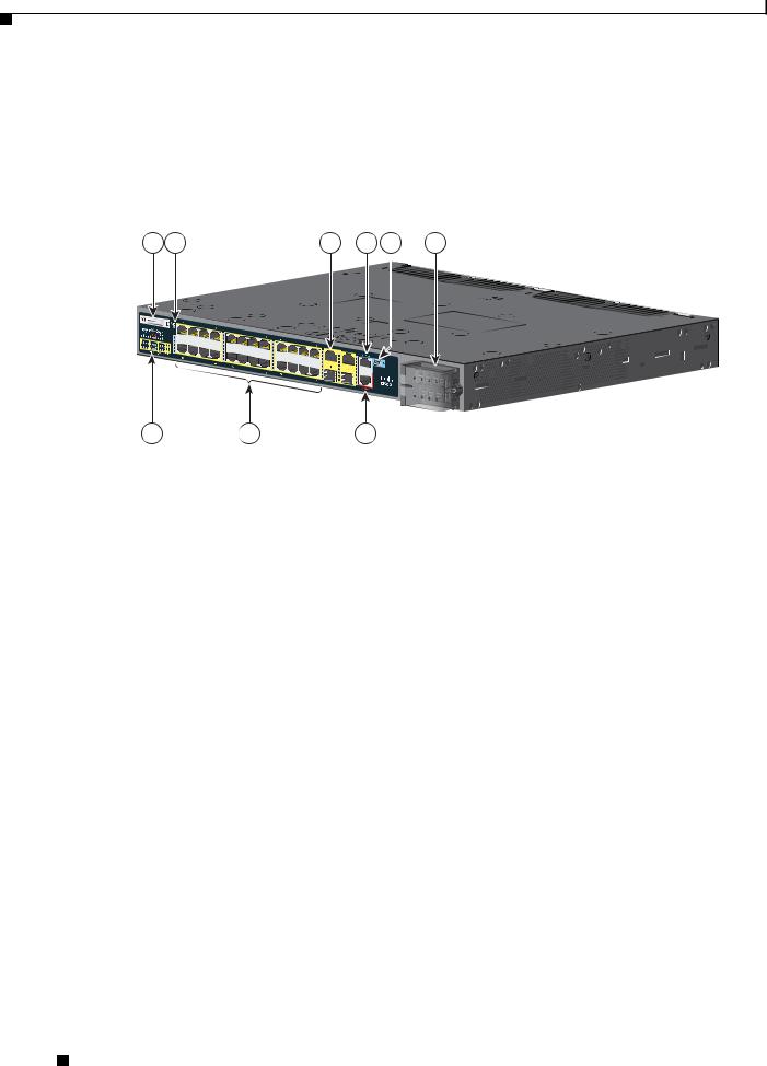
The 10/100 Fast Ethernet downlink ports in Figure 1-1 are grouped in pairs. The first member of the pair (port 1) is above the second member (port 2) on the left. Port 3 is above port 4, and so on.
The dual-purpose ports are numbered 1 and 2.
Figure 1-1 Cisco IE-3010-24TC Cable-Side View
1 |
3 |
5 |
6 |
7 |
8 |
Cisco IE 3010
208362
2 |
4 |
9 |
|
|
|
|
|
|
|
1 |
SD1 flash memory card slot |
|
6 |
RJ-45 console port |
2 |
LEDs |
|
7 |
USB (mini-Type B) console port |
|
|
|
|
|
3 |
Express Setup button |
|
8 |
Power-input terminal |
|
|
|
|
|
4 |
10/100 ports |
|
9 |
Alarm port |
|
|
|
|
|
5 |
Dual purpose ports |
|
|
|
|
|
|
|
|
1. SD = Secure Digital
Cisco IE 3010 Switch Hardware Installation Guide
1-2 |
78-19581-02 |
|
|
Chapter 1 Product Overview
Cable Side
The100BASE-FX SFP ports and the 10/100 PoE ports are grouped in pairs. The first member of the pair (port 1) is above the second member (port 2) on the left. Port 3 is above port 4, and so on.
The dual-purpose ports are numbered 1 and 2.
Figure 1-2 Cisco IE-3010-16S-8PC Cable-Side View
1 |
3 |
5 |
6 |
7 |
8 |
9 |
|
|
|
|
|
|
|
|
|
|
|
|
|
|
|
|
|
|
|
POW |
|
|
|
|
|
|
|
|
|
|
|
|
|
|
|
|
|
|
|
|
|
|
|
|
|
|
|
|
|
|
|
|
|
|
|
|
|
|
|
|
|
|
|
|
|
|
|
|
|
|
|
|
|
|
|
|
|
|
|
|
|
|
|
|
|
|
|
|
|
|
|
|
|
|
|
|
|
ER OVER |
|
|
|
|||
|
|
|
|
|
|
|
|
|
|
|
|
|
|
|
|
|
|
|
|
ETHERNET |
|
||||
|
|
|
|
|
|
|
|
|
|
|
|
|
|
|
|
|
|
|
POW |
||||||
|
|
|
|
|
|
|
|
|
|
|
|
|
|
|
|
|
|
|
|||||||
|
|
|
|
|
|
|
|
|
|
|
|
|
|
|
|
|
|
|
ER OVER |
||||||
|
|
|
|
|
|
|
|
|
|
|
|
|
|
|
|
|
|
|
|
ETHERNET |
|
|
|
|
Cisco |
|
|
|
|
|
|
|
|
|
|
|
|
|
|
|
|
|
|
|
|
|
|
|
|
|
|
|
|
|
|
|
|
|
|
|
|
|
|
|
|
|
|
|
|
|
|
|
|
|
|
|
|
|
|
|
|
|
|
|
|
|
|
|
|
|
|
|
|
|
|
|
|
|
|
|
|
|
|
|
|
|
|
|
|
|
|
|
|
|
|
|
|
|
|
|
|
|
|
|
|
|
|
|
IE 3010 |
|
|
|
|
|
|
|
|
|
|
|
|
||||||||||||||
|
|
|
|
|
|
|
|
|
|
|
|
|
|
|
|
|
|
|
|
|
|
|
|
|
|
2 |
4 |
10 |
|||||||||||||||||||||||
208363
1 |
SD flash memory card slot |
6 |
Dual purpose ports |
|
|
|
|
2 |
LEDs |
7 |
RJ-45 console port |
|
|
|
|
3 |
Express Setup button |
8 |
USB (mini-Type B) console port |
|
|
|
|
4 |
100BASE-FX SFP ports |
9 |
Power-input terminal |
|
|
|
|
5 |
10/100 PoE ports |
10 |
Alarm port |
|
|
|
|
10/100 Fast Ethernet Ports
You can set the 10/100 ports on the switch to operate in any combination of half duplex, full duplex, or 10 or 100 Mb/s. You can set the ports for speed and duplex autonegotiation. The default setting is autonegotiate.
When set for autonegotiation, the switch determines the speed and duplex settings of the attached device and advertises its own capabilities. If the connected device also supports autonegotiation, the switch negotiates the best connection (the fastest line speed that both devices support and full-duplex transmission if the attached device supports it) and configures itself accordingly. In all cases, the attached device must be within 328 feet (100 meters).
PoE Ports
Warning Voltages that present a shock hazard may exist on Power over Ethernet (PoE) circuits if interconnections are made using uninsulated exposed metal contacts, conductors, or terminals. Avoid using such interconnection methods, unless the exposed metal parts are located within a restricted access location and users and service people who are authorized within the restricted access location are made aware of the hazard. A restricted access area can be accessed only through the use of a special tool, lock and key or other means of security. Statement 1072
Cisco IE 3010 Switch Hardware Installation Guide
|
78-19581-02 |
1-3 |
|
|
|

Chapter 1 Product Overview
Cable Side
The 10/100 PoE ports on the Cisco IE-3010-16S-8PC switches provide PoE support for devices that are compliant with IEEE 802.3af. The Cisco prestandard PoE is also supported for Cisco IP Phones and Cisco Aironet Access Points. The PoE ports on the switch deliver up to 15.4 W of PoE. Any four of the eight ports are designated as high priority PoE ports, while the other four ports are designated as low priority PoE ports. When both the power-supply modules are installed, the system has enough power to support all eight ports as PoE ports. In case one of the power-supply modules fails, the power to the low priority PoE ports is dropped, while power to the high priority PoE ports remains uninterrupted.
On a per-port basis, you control whether or not a port automatically provides power when an IP phone or an access point is connected.
The 10/100 PoE ports use RJ-45 connectors with Ethernet pinouts. The maximum cable length is 328 feet (100 meters). The 100BASE-TX and 1000BASE-T traffic requires Category 5, Category 5e, or Category 6 unshielded twisted pair (UTP) cable. The 10BASE-T traffic can use Category 3 or Category 4 UTP cable.
For information about configuring and monitoring PoE ports, see the switch software configuration guide on Cisco.com.
For information about port connections and port specifications, see the “Connecting Devices to the Ethernet Ports” section on page 2-25 and the “Connector and Cable Specifications” section on page B-1.
Note The output of the PoE circuit has been evaluated as a Limited Power Source (LPS) per IEC 60950-1.
Dual-Purpose Ports
You can configure the dual-purpose ports on the switch as either 10/100/1000 ports or as SFP-module ports. You can set the 10/100/1000 ports to autonegotiate, or you can configure them as fixed 10, 100, or 1000 Mb/s (Gigabit) Ethernet ports.
By default, the switch selects the medium for each dual-purpose port (10/100/1000BASE-T or SFP). When a link is achieved on one media type, the switch disables the other media type until the active link goes down. If links are active on both media, the SFP-module port has priority, but you can use the media-type interface configuration command to manually designate the port as an RJ-45 port or an SFP port.
You can configure the speed and duplex settings consistent with the selected media type. For information on configuring interfaces, see the switch software configuration guide.
Cisco IE 3010 Switch Hardware Installation Guide
1-4 |
78-19581-02 |
|
|

Chapter 1 Product Overview
Cable Side
SFP Modules
The switch Ethernet SFP modules provide connections to other devices. These field-replaceable transceiver modules provide the uplink interfaces.The modules have LC connectors for fiber-optic connections or RJ-45 connectors for copper connections. You can use any combination of the supported SFP modules listed in Table 1-2.
Table 1-2 Maximum Operating Temperature
Type of SFP Module |
Model |
|
|
|
|
Rugged and Industrial SFPs |
• |
GLC-SX-MM-RGD |
–40 to 140°F (–40 to 60°C) |
• |
GLC-LX-SM-RGD |
|
||
|
• |
GLC-FE-100LX-RGD |
|
• |
GLC-FE-100FX-RGD |
|
• GLC-ZX-SM-RGD |
|
|
|
|
Commercial SFPs |
• |
GLC-BX-D with DOM support |
32 to 113°F (0 to 45°C) |
• |
GLC-BX-U with DOM support |
|
||
|
• |
GLC-FE-100LX |
|
• |
GLC-FE-100BX-D |
|
• |
GLC-FE-100BX-U |
|
• |
GLC-FE-100FX |
|
• |
GLC-FE-100EX |
|
• |
GLC-FE-100ZX |
|
• CWDM SFP with DOM support |
|
|
|
|
Extended temperature SFPs |
• |
SFP-GE-L with digital optical monitoring |
23 to 140°F (–5 to 60°C) |
|
(DOM) support |
|
• SFP-GE-S with DOM support |
|
|
• SFP-GE-Z with DOM support |
|
|
• GLC-EX-SMD with DOM support |
|
|
|
|
For information about SFP modules, see your SFP module documentation and the “Installing and Removing SFP Modules” section on page 2-20. For cable specifications, see Appendix B, “SFP Module Cables.”
Cisco IE 3010 Switch Hardware Installation Guide
|
78-19581-02 |
1-5 |
|
|
|
Chapter 1 Product Overview
Cable Side
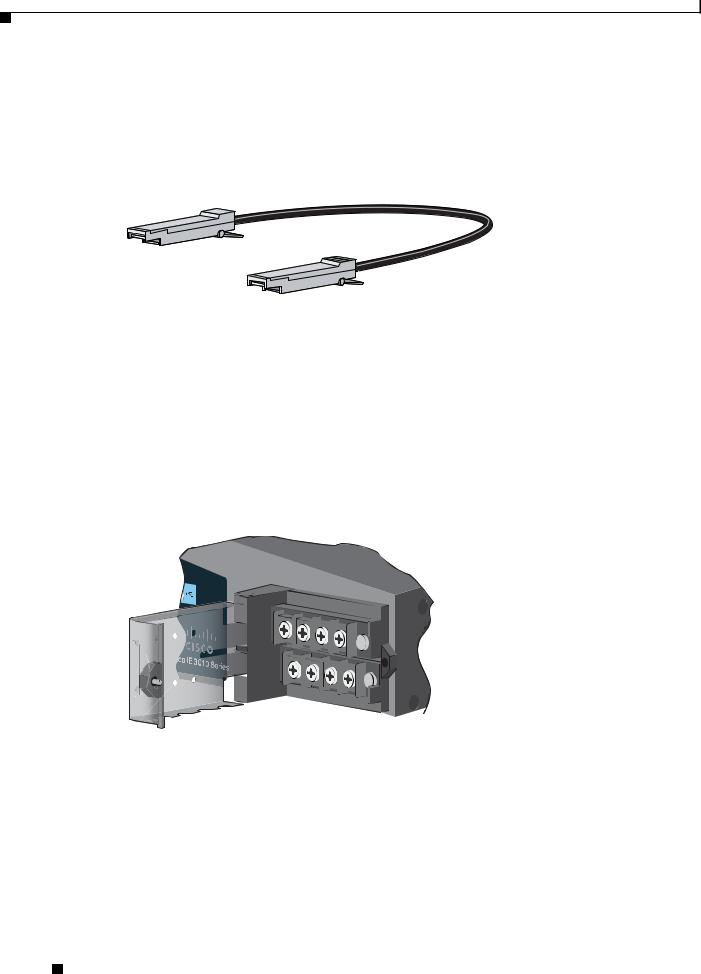
SFP Module Patch Cable
The switch uses an SFP-module patch cable, a 0.5-meter, copper, passive cable with SFP module connectors at each end (see Figure 1-3). The patch cable connects two switches in a cascaded configuration.
Figure 1-3 SFP-Module Patch Cable
See the “Inserting and Removing the SFP Module Patch Cable” section on page 2-21 for information about using the SFP module patch cable.
You can order this cable (part number CAB-SFP-50CM=).
Power-Input Terminal
The power-input terminal provides screw terminals for the AC and DC power connections. The switch can operate with one or two power supplies. If one of the power sources fail, the other continues to power the switch. See Chapter 3, “Power Supply Installation,” for information.
Figure 1-4 Power-Input Terminal
208415
Alarm Ports
The switch has four alarm inputs and one alarm output. The alarm setting is open or closed.
•Open means that the normal condition has current flowing through the contact (referred to as a normally closed contact). The alarm is generated when the current stops.
•Closed means that no current flows through the contact (referred to as a normally open contact). The alarm is generated when the current flows.
Cisco IE 3010 Switch Hardware Installation Guide
1-6 |
78-19581-02 |
|
|

Chapter 1 Product Overview
Cable Side
Alarm Input
The alarm input is a dry-contact alarm port. You can connect up to four alarm inputs from devices, such as a door, a temperature gauge, or a fire alarm, to the alarm port. You can use the CLI to set the alarm severity to minor, major, or critical. An alarm generates a system message and turns on an LED. See the “Alarm LEDs” section on page 1-9 for the LED descriptions.
Alarm Output
The alarm output can be configured as a minor or major alarm. Output alarms often control an external alarm, such as a bell or a light. To connect an external alarm device to the relay, you connect two relay contact wires to complete the electrical circuit. See Figure B-4 on page B-3 for information on the alarm pinouts.
Management Ports
You can connect the switch to a PC running Microsoft Windows or to a terminal server through either the RJ-45 console port or the USB console port.
•RJ-45 console port. The RJ-45 connection uses an RJ-45-to-DB-9 female cable.
•USB mini-Type B console port (5-pin connector). The USB connection uses a USB Type A-to-5-pin mini-Type B cable.
The USB console interface speeds are the same as the RJ-45 console interface speeds.
To use the USB console port, you must install the Cisco Windows USB device driver on the device that is connected to the USB console port (device running with Microsoft Windows).
Note For information about downloading the Cisco USB device driver, see the “Installing the Cisco Microsoft Windows USB Device Drivers” section on page C-4.
With the Cisco Windows USB device driver, connecting and disconnecting the USB cable from the console port does not affect Windows HyperTerminal operations. Mac OS X or Linux require no special drivers.
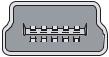
Note The 5-pin mini-Type B connectors resemble the 4-pin mini-Type B connectors. They are not compatible. Use only the 5-pin mini-Type B. See Figure 1-5.
Figure 1-5 USB Mini-Type B Port
 253163
The configurable inactivity timeout reactivates the RJ-45 console port if the USB console port is activated, but no input activity occurs on it for a specified time period. When the USB console port deactivates due to a timeout, you can restore its operation by disconnecting and reconnecting the USB cable. For information on using the CLI to configure the USB console interface, see the switch software guide.
Cisco IE 3010 Switch Hardware Installation Guide
|
78-19581-02 |
1-7 |
|
|
|
Chapter 1 Product Overview
Cable Side
LEDs
You can use the switch system and port LEDs to monitor switch activity and performance.
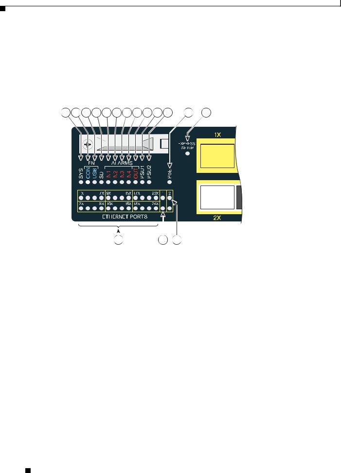
Switch Panel LEDs
Figure 1-6 Switch LEDs (Cable Side)
1 |
2 |
3 |
4 |
5 |
6 |
7 |
8 |
9 |
10 11 |
12 |
13 |
|
|||||||
|
|
|
|
|
|
|
|
|
|
|
|
|
|
|
|
|
|
|
|
|
|
|
|
|
|
|
|
|
|
|
|
|
|
|
|
|
|
|
|
|
|
|
|
|
|
|
|
|
|
|
|
|
|
|
|
|
|
|
|
|
|
|
|
|
|
|
|
|
|
|
|
|
|
|
|
|
|
|
|
|
|
|
|
|
|
|
|
|
|
|
|
|
|
|
|
|
|
|
|
|
|
|
|
|
|
|
|
|
|
|
|
|
|
|
|
|
|
|
|
|
|
|
|
|
|
|
|
|
|
|
|
|
|
|
|
|
|
|
|
|
|
|
|
|
|
|
|
|
|
|
|
|
|
|
|
|
|
|
|
|
|
|
|
|
|
|
|
|
|
|
|
|
|
|
|
|
|
|
|
|
|
|
|
|
|
|
|
|
|
|
|
|
|
|
|
|
|
|
|
|
|
|
|
|
16 |
207198 |
|
|
|
|
|
|
|||
|
|
|
|
|
|||
|
|
|
|
|
|
||
|
14 |
15 |
|
||||
|
|
|
|
|
|
|
|
1 |
SYS (system) |
|
|
|
9 |
OUT (alarm output) |
|
|
|
|
|
|
|
|
|
2 |
CON (RJ-45 console) |
|
|
|
10 |
PSU1 (power supply 1) |
|
|
|
|
|
|
|
|
|
3 |
USB (mini-USB console) |
|
|
|
11 |
PSU2 (power supply 2) |
|
|
|
|
|
|
|
|
|
4 |
SD (SD flash memory card) |
|
|
|
12 |
PoE1 |
|
5 |
IN1 (alarm input 1) |
|
|
|
13 |
Express Setup button |
|
|
|
|
|
|
|
|
|
6 |
IN2 (alarm input 2) |
|
|
|
14 |
Ethernet ports |
|
|
|
|
|
|
|
|
|
7 |
IN3 (alarm input 3) |
|
|
|
15 |
SFP module port |
|
|
|
|
|
|
|
|
|
8 |
IN4 (alarm input 4) |
|
|
|
16 |
10/100/1000 port |
|
|
|
|
|
|
|
|
|
1. Only on the Cisco IE-3010-16S-8PC switch.
Cisco IE 3010 Switch Hardware Installation Guide
1-8 |
78-19581-02 |
|
|

Chapter 1 Product Overview
Cable Side
System LED
Table 1-3 |
System LED |
|
|
|
|
Color |
|
System Status |
|
|
|
Off |
|
System is not powered on. |
|
|
|
Blinking green |
|
POST1 is in progress. |
Green |
|
System is operating normally. |
|
|
|
Amber |
|
System is receiving power but is not functioning properly. |
|
|
|
1. POST = power-on self-test.
Power-Supply Module LEDs
The switch power-supply module LEDs are labeled PSU1 and PSU2 (on the switch) and PSU OK (on the power-supply module). They show whether power-supply modules 1 and 2 are receiving power. See Figure 1-6 and Figure 1-9.
Table 1-4 |
Power-Supply Module LEDs |
|
|
|
|
Color |
|
System Status |
|
|
|
Off |
|
Power-supply module (1 or 2) is not installed. |
|
|
|
Green |
|
Valid input is present, and the output is within the operating range. |
|
|
|
Red |
|
Valid input is present, and the output is outside the operating range or is not present. |
|
|
|
Blinking red |
|
Valid input is not present. |
|
|
|
Alarm LEDs
Table 1-5 |
Alarm Input LEDs |
||
|
|
|
|
Color |
|
System Status |
|
|
|
|
|
Off |
|
No alarm |
|
|
|
|
|
Amber |
|
Minor alarm |
|
|
|
|
|
Red |
|
Major alarm |
|
|
|
|
|
Blinking red |
|
Critical alarm |
|
|
|
|
|
Table 1-6 |
Alarm Output LED |
||
|
|
|
|
Color |
|
System Status |
|
|
|
|
|
Green |
|
No alarm |
|
|
|
|
|
Red |
|
Relay closed, alarm present |
|
|
|
|
|
Cisco IE 3010 Switch Hardware Installation Guide
|
78-19581-02 |
1-9 |
|
|
|

Chapter 1 Product Overview
Cable Side
Console LEDs
The console LEDs show which console port is in use. See Figure 1-6 and Figure 1-9 for the LED locations.
If you connect a cable to a console port, the switch automatically uses that port for console communication. If you connect two console cables, the USB console port has priority.
Table 1-7 |
RJ-45 and USB Console Port LEDs |
||
|
|
|
|
LED |
|
Color |
Description |
|
|
|
|
RJ-45 console port |
Green |
RJ-45 console port is active. |
|
|
|
|
USB console port LED is off. |
|
|
|
|
|
|
Off |
Port is not active. |
|
|
|
USB console port is active. |
|
|
|
|
USB console port |
Green |
USB console port is active. |
|
|
|
|
RJ-45 console port LED is off. |
|
|
|
|
|
|
Off |
Port is not active. |
|
|
|
RJ-45 console port is active. |
|
|
|
|
Port LEDs
RJ-45 ports and SFP-module slots have port LEDs. Port LEDs, as a group or individually, provide information about the switch and about the individual ports.
Table 1-8 |
Meaning of Port LED Colors |
|
|
|
|
LED Color |
|
Meaning |
|
|
|
Off |
|
No link or port was administratively shut down. |
|
|
|
Green |
|
Link present but not sending or receiving data. |
|
|
|
Blinking green |
|
Activity. Port is sending or receiving data. |
|
|
|
Alternating |
|
Link fault. Error frames can affect connectivity, and errors such as excessive |
green-amber |
|
collisions, CRC errors, and alignment and jabber errors are monitored for link |
|
|
faults. |
|
|
|
Amber |
|
Port is blocked by Spanning Tree Protocol (STP) and is not forwarding data. |
|
|
After a port is reconfigured, the port LED is amber for up to 30 seconds as STP |
|
|
searches for loops. |
|
|
|
Cisco IE 3010 Switch Hardware Installation Guide
1-10 |
78-19581-02 |
|
|

Chapter 1 Product Overview
Cable Side
PoE LED
Table 1-9 |
PoE LED |
|
|
|
|
Color |
|
Meaning |
|
|
|
Off |
|
PoE is not enabled. |
|
|
|
Green |
|
PoE is enabled. Ports are functioning correctly. |
|
|
|
Amber |
|
PoE is enabled, but an error is present. |
|
|
|
Dual-Purpose Port LEDs
The dual-purpose port LEDs identify the connection as either a copper-based connector or an SFP module. The ports can autonegotiate, or you can manually configure each dual-purpose port as either 10/100/1000 with copper connectors or as an SFP-module port, but not as both types at the same time. See Table 1-8 for LED descriptions.
SD Flash Memory Card LED
Table 1-10 |
SD Flash Memory Card LED |
|
|
|
|
Color |
|
System Status |
|
|
|
Off / blinking green |
SD flash memory card transfer in progress. |
|
|
|
|
Blinking amber |
|
SD flash memory card is not present (slow blinking). |
|
|
Unsupported SD flash memory card is detected (fast blinking). |
|
|
|
Amber |
|
Error accessing the SD flash memory card. |
|
|
Cisco IOS boot image cannot be found. |
|
|
|
Green |
|
SD flash memory card is functioning. |
|
|
|
SD Flash Memory Card
The switch ships with the Secure Digital (SD) flash memory card installed. See Figure 1-1 and Figure 1-2. The switch stores the Cisco IOS software images and the switch configuration on the card.
You should not remove the card unless you want to use it in a replacement switch. You then do not have to reconfigure the new switch. See the “Replacing the SD Flash Memory Card” section on page 2-23 for information.
Cisco IE 3010 Switch Hardware Installation Guide
|
78-19581-02 |
1-11 |
|
|
|
Chapter 1 Product Overview
Power-Supply Side
Power-Supply Side
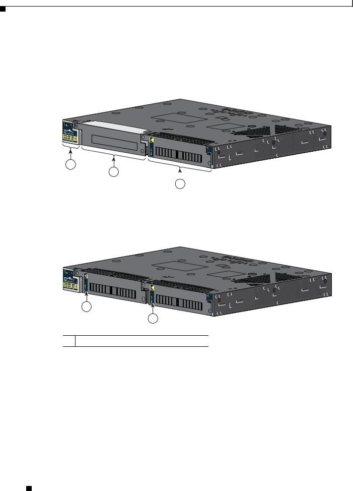
The power-supply side has the LED panel and two power-supply slots for the removable power supplies. See Figure 1-7 and Figure 1-8.
Figure 1-7 Switch with One Power-Supply Module
Cisco IE |
3010 |
|
Sw |
|
|
|
itchSeries |
|
|
|
-D C |
|
|
PW R-RG D -LO W |
|
|
2 |
|
|
|
|
|
|
|
|
|
|
|
3 |
|||
|
|
|
|
|
|
1 |
LED panel |
|
3 |
Power-supply slot 2 |
|
|
|
|
|
|
|
2 |
Power-supply slot 1 |
|
|
|
|
|
|
|
|
|
|
Figure 1-8 |
Switch with Both Power-Supply Modules |
||||
Cisco IE |
3010 |
|
Sw |
|
|
|
itchSeries |
|
PW R-RG D -LO W -D C
PW R-RG D -LO W -D C
1
1
1 PSU OK LED
For a description of the PSU OK LED, see Table 1-4 on page 1-9.
Cisco IE 3010 Switch Hardware Installation Guide
1-12 |
78-19581-02 |
|
|
Chapter 1 Product Overview
Power-Supply Side
Power-Supply Side LEDs
Figure 1-9 |
|
Switch LEDs |
|
|
|
|||||
1 |
2 |
3 |
4 |
5 |
6 |
7 |
8 |
9 |
10 11 |
12 |
Cisco IE 3010
 Switch Series
|
|
|
|
|
|
|
|
|
208364 |
|
|
|
|
|
|
|
|
|
|
|
|
||
|
|
|
|
|
|
|
|
|
|
||
|
|
|
|
|
|
|
|
|
|
||
|
|
|
|
|
15 |
|
|
||||
|
|
|
|
|
|
|
|
||||
|
13 |
|
14 |
|
|
||||||
|
|
|
|
|
|
|
|
|
|
|
|
1 |
SYS (system) |
|
|
|
|
9 |
OUT (alarm output) |
||||
|
|
|
|
|
|
|
|
|
|
|
|
2 |
CON (console) |
|
|
|
|
10 |
PSU1 (power supply 1) |
||||
|
|
|
|
|
|
|
|
|
|
|
|
3 |
USB LED |
|
|
|
|
11 |
PSU2 (power supply 2) |
||||
|
|
|
|
|
|
|
|
|
|
|
|
4 |
SD (SD flash memory card) |
|
|
|
|
12 |
PoE1 |
||||
5 |
IN1 (alarm input 1) |
|
|
|
|
13 |
Ethernet ports |
||||
|
|
|
|
|
|
|
|
|
|
|
|
6 |
IN2 (alarm input 2) |
|
|
|
|
14 |
10/100/1000 port |
||||
|
|
|
|
|
|
|
|
|
|
|
|
7 |
IN3 (alarm input 3) |
|
|
|
|
15 |
SFP port |
||||
|
|
|
|
|
|
|
|
|
|
|
|
8 |
IN4 (alarm input 4) |
|
|
|
|
|
|
||||
|
|
|
|
|
|
|
|
|
|
|
|
1. Only on the Cisco IE-3010-16S-8PC switch.
For a description of the LEDs, see the “LEDs” section on page 1-8.
Cisco IE 3010 Switch Hardware Installation Guide
|
78-19581-02 |
1-13 |
|
|
|

Chapter 1 Product Overview
Management Options
Power Supply Features
The switch has two slots for power-supply modules:
•PWR-RGD-LOW-DC/IA: low-voltage DC (for voltage information, see Table A-6)
•PWR-RGD-AC-DC/IA: high-voltage AC or DC (for voltage information, see Table A-5) The switch supports these power-supply module combinations:
•Single low-voltage DC
•Single high-voltage AC or DC
•Two high-voltage AC or DC
•Two low-voltage DC
•One high-voltage AC or DC and one low-voltage DC
For information on installing the power-supply modules, see Chapter 3, “Power Supply Installation.” See Table 1-4 for information on the power supply LEDs.
Management Options
•Cisco IOS CLI
You can configure and monitor the switch from the CLI. Connect your management station to the switch console port or use Telnet from a remote management station. See the switch command reference on Cisco.com for information.
•SNMP network management
You can manage switches from a Simple Network Management Protocol (SNMP)-compatible management station that is running platforms such as HP OpenView or SunNet Manager. The switch supports a comprehensive set of Management Information Base (MIB) extensions and four Remote Monitoring (RMON) groups. See the switch software configuration guide on Cisco.com and the documentation that came with your SNMP application for information.
Network Configurations
See the switch software configuration guide on Cisco.com for an explanation of network configuration concepts. The software configuration guide also provides network configuration examples for creating dedicated network segments that are interconnected through Ethernet connections.
Cisco IE 3010 Switch Hardware Installation Guide
1-14 |
78-19581-02 |
|
|

C H A P T E R 2
Switch Installation
Read the topics and perform the procedures in this order:
•Warnings, page 2-1
•Installation Guidelines, page 2-3
•Verifying Switch Operation, page 2-3
•Installing the Switch, page 2-4
•Installing and Removing SFP Modules, page 2-20
•Inserting and Removing the SFP Module Patch Cable, page 2-21
•Replacing the SD Flash Memory Card, page 2-23
•Connecting Devices to the Ethernet Ports, page 2-25
•Where to Go Next, page 2-27
Warnings
These warnings are translated into several languages in the Regulatory Compliance and Safety Information for the Cisco IE 3010 Switch document that ships on the documentation CD.
These warning statements apply to all the switches:
Warning Before working on equipment that is connected to power lines, remove jewelry (including rings, necklaces, and watches). Metal objects will heat up when connected to power and ground and can cause serious burns or weld the metal object to the terminals. Statement 43
Warning Read the installation instructions before you connect the system to its power source. Statement 1004
Warning This unit is intended for installation in restricted access areas. A restricted access area can be accessed only through the use of a special tool, lock and key, or other means of security.
Statement 1017
Cisco IE 3010 Switch Hardware Installation Guide
|
78-19581-02 |
2-1 |
|
|
|

Chapter 2 Switch Installation
Warnings
Warning This equipment must be grounded. Never defeat the ground conductor or operate the equipment in the absence of a suitably installed ground conductor. Contact the appropriate electrical inspection authority or an electrician if you are uncertain that suitable grounding is available. Statement 1024
Warning This unit might have more than one power supply connection. All connections must be removed to de-energize the unit. Statement 1028
Warning Only trained and qualified personnel should be allowed to install, replace, or service this equipment.
Statement 1030
Warning Ultimate disposal of this product should be handled according to all national laws and regulations.
Statement 1040
Warning For connections outside the building where the equipment is installed, the following ports must be connected through an approved network termination unit with integral circuit protection. 10/100/1000 Ethernet Statement 1044
Warning To prevent the system from overheating, do not operate it in an area that exceeds the maximum recommended ambient temperature of:
140°F (60°C) Statement 1047
Warning Installation of the equipment must comply with local and national electrical codes. Statement 1074
Note For U.S. installations, refer to national electrical code ANSI/NFPA 70.
Warning To prevent airflow restriction, allow clearance around the ventilation openings to be at least: 1.75 in. (4.4 cm). Statement 1076
Warning Avoid using or servicing any equipment that has outdoor connections during an electrical storm. There may be a risk of electric shock from lightning. Statement 1088
Cisco IE 3010 Switch Hardware Installation Guide
2-2 |
78-19581-02 |
|
|

Chapter 2 Switch Installation
Installation Guidelines
Installation Guidelines
Before installing the switch, verify that these guidelines are met:
•Cabling is away from sources of electrical noise, such as radios, power lines, and fluorescent lighting fixtures. Make sure that the cabling is away from other devices that might damage the cables.
•Operating environment is within the ranges listed in Appendix A, “Technical Specifications.”
•Relative humidity around the switch does not exceed 95 percent (noncondensing).
•Altitude at the installation site is not higher than 10,000 feet.
•For 10/100 and 10/100/1000 fixed ports, cable lengths from the switch to connected devices are not more than 328 feet (100 meters).
•For cable lengths for small form-factor pluggable (SFP)-module connections, see the “SFP Module Cables” section on page B-4 and the module documentation.
•Airflow around the switch and through the vents is unrestricted. To prevent overheating, the switch must meet the minimum clearance of 1.75 inches (4.4 cm) at the top and bottom.
Note If the switch is installed in a closed or multirack assembly, the temperature around it might be greater than normal room temperature.
Verifying Switch Operation
Before installing the switch in a rack or on a wall, you should power the switch and verify that the switch passes the power-on self-test (POST).
To wire the switch to the power source, see Chapter 3, “Power Supply Installation.”
When the switch begins POST, the SYS LED blinks green, and the other LEDs stay green. When the switch passes POST, the SYS LED turns green. The other LEDs turn off and return to their operating status. If the switch fails POST, the SYS LED is amber.
Note Contact Cisco Systems immediately if your switch fails POST.
After a successful POST, disconnect the power from the switch. For more information, see Chapter 3, “Power Supply Installation.” See the “Installing the Switch” section on page 2-4 to install the switch in a rack or on a wall.
Cisco IE 3010 Switch Hardware Installation Guide
|
78-19581-02 |
2-3 |
|
|
|

Chapter 2 Switch Installation
Installing the Switch
Installing the Switch
•Rack-Mounting, page 2-4
•Wall-Mounting, page 2-15
Note If the switch is wall-mounted in an enclosure, follow these minimum clearances:
-Sides of switch (facing up and facing down): 3.75 in. (9.52 cm)
-Port side 3.0 in. (7.62 cm)
-Power supply side: 5.25 in. (13.33 cm)
-Cover side (side not facing wall): 1.75 in. (4.44 cm)
-Base side (facing wall): 0 in. (0 cm)
Rack-Mounting
To rack-mount the switch, select the rack size and follow the steps in these sections:
•Attaching Brackets for 19-Inch Racks, page 2-5
•Attaching Brackets for 19-Inch Racks for IP-30 Compliance (Optional), page 2-6
•Attaching Brackets for 23-Inch Racks, page 2-12
•Attaching Brackets for ETSI Racks, page 2-13
•Rack-Mounting the Switch, page 2-14
.
Warning To prevent bodily injury when mounting or servicing this unit in a rack, you must take special precautions to ensure that the system remains stable. The following guidelines are provided to ensure your safety:
•This unit should be mounted at the bottom of the rack if it is the only unit in the rack.
•When mounting this unit in a partially filled rack, load the rack from the bottom to the top with the heaviest component at the bottom of the rack.
•If the rack is provided with stabilizing devices, install the stabilizers before mounting or servicing the unit in the rack. Statement 1006
Warning For mounting railway-application equipment and for EN50155 standard compliance, the switch must be installed only in a rack mid-mounting position. If you install the switch in a front rack-mounting (cable side or power supply side) position or in a wall-mounting position, a mechanical failure can occur that results in the switch becoming detached from the rack. Statement 403
Cisco IE 3010 Switch Hardware Installation Guide
2-4 |
78-19581-02 |
|
|

Chapter 2 Switch Installation
Installing the Switch
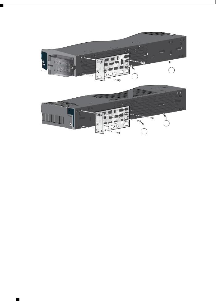
Attaching Brackets for 19-Inch Racks
Figure 2-1 and Figure 2-2 show how to attach brackets to the switches.
Figure 2-1 Attaching Brackets for 19-Inch Racks
Cisco IE 3010
1
2
Cisco IE 3010
3
2
|
|
|
208366 |
|
|
|
4 |
|
|
|
2 |
|
|
|
|
1 |
Mid-mounting position |
3 |
Cable-side mounting position |
|
|
|
|
2 |
Phillips flat-head screws |
4 |
Power-supply-side mounting position |
|
|
|
|
Cisco IE 3010 Switch Hardware Installation Guide
|
78-19581-02 |
2-5 |
|
|
|
Chapter 2 Switch Installation
Installing the Switch
Figure 2-2 Attaching Brackets for 19-Inch Racks
Cisco CGS 2520
2
1
|
|
|
207231 |
|
|
|
3 |
|
|
|
1 |
|
|
|
|
1 |
Phillips flat-head screws |
3 |
Power-supply-side mounting position |
|
|
|
|
2 |
Cable-side-mounting position |
|
|
|
|
|
|
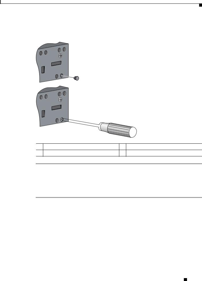
Attaching Brackets for 19-Inch Racks for IP-30 Compliance (Optional)
Before installing the mounting brackets, you need to install the rubber plugs in the unused mounting holes. The rubber plugs are not supplied with the switch. You can order a kit (part number IE-3010-IP30KIT) containing the rubber plugs.
You can order a kit (part number IE-3010-IP30KIT) that contains the rubber plugs.
Figure 2-3 shows a close-up of the rubber plug. You can install the rubber plugs in the holes as shown in Figure 2-4 and Figure 2-5.
Cisco IE 3010 Switch Hardware Installation Guide
2-6 |
78-19581-02 |
|
|
Chapter 2 Switch Installation
Installing the Switch
Figure 2-3 Inserting the Rubber Plug
1
2
|
|
|
3 |
|
|
|
255738 |
|
1 |
Rubber plug |
3 Screwdriver |
|
2 |
Switch |
|
Step 1 |
Identify your bracket mounting position. See Figure 2-6 or Figure 2-7. |
||
Step 2 |
Insert the rubber plugs in the appropriate holes. See Figure 2-4 or Figure 2-5. Follow the same procedure |
||
|
on the other side of the switch. |
|
|
Step 3 |
Use a screwdriver or pen to completely push in the rubber plugs. See Figure 2-3. |
||
Step 4 |
Install the brackets on both sides of the switch. See Figure 2-6 or Figure 2-7. |
||
Cisco IE 3010 Switch Hardware Installation Guide
|
78-19581-02 |
2-7 |
|
|
|
Chapter 2 Switch Installation
Installing the Switch
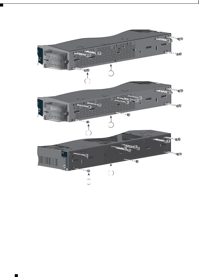
Figure 2-4 Inserting the Rubber Plugs
2
1
3
1
|
|
|
|
|
|
255739 |
|
|
|
|
|
|
|
|
|
|
4 |
|
||
|
|
|
|
|
|
|
|
|
1 |
|
|
|
|
|
|
|
|
|
|
|
1 |
Rubber plug |
|
|
3 |
|
Cable-side mounting position |
|
|
|
|
|
|
|
2 |
Mid-mounting position |
|
|
4 |
|
Power-supply-side mounting position |
|
|
|
|
|
|
|
Cisco IE 3010 Switch Hardware Installation Guide
2-8 |
78-19581-02 |
|
|
Loading...