


Cisco UCS C200 Server
Installation and Service Guide
Covers UCS C200 Server Generations M1 and M2
February 22, 2013
Americas Headquarters
Cisco Systems, Inc. 170 West Tasman Drive
San Jose, CA 95134-1706 USA http://www.cisco.com Tel: 408 526-4000
800 553-NETS (6387) Fax: 408 527-0883
Text Part Number: OL-20732-02
THE SPECIFICATIONS AND INFORMATION REGARDING THE PRODUCTS IN THIS MANUAL ARE SUBJECT TO CHANGE WITHOUT NOTICE. ALL STATEMENTS, INFORMATION, AND RECOMMENDATIONS IN THIS MANUAL ARE BELIEVED TO BE ACCURATE BUT ARE PRESENTED WITHOUT WARRANTY OF ANY KIND, EXPRESS OR IMPLIED. USERS MUST TAKE FULL RESPONSIBILITY FOR THEIR APPLICATION OF ANY PRODUCTS.
THE SOFTWARE LICENSE AND LIMITED WARRANTY FOR THE ACCOMPANYING PRODUCT ARE SET FORTH IN THE INFORMATION PACKET THAT SHIPPED WITH THE PRODUCT AND ARE INCORPORATED HEREIN BY THIS REFERENCE. IF YOU ARE UNABLE TO LOCATE THE SOFTWARE LICENSE OR LIMITED WARRANTY, CONTACT YOUR CISCO REPRESENTATIVE FOR A COPY.
The following information is for FCC compliance of Class A devices: This equipment has been tested and found to comply with the limits for a Class A digital device, pursuant to part 15 of the FCC rules. These limits are designed to provide reasonable protection against harmful interference when the equipment is operated in a commercial environment. This equipment generates, uses, and can radiate radio-frequency energy and, if not installed and used in accordance with the instruction manual, may cause harmful interference to radio communications. Operation of this equipment in a residential area is likely to cause harmful interference, in which case users will be required to correct the interference at their own expense.
The following information is for FCC compliance of Class B devices: This equipment has been tested and found to comply with the limits for a Class B digital device, pursuant to part 15 of the FCC rules. These limits are designed to provide reasonable protection against harmful interference in a residential installation. This equipment generates, uses and can radiate radio frequency energy and, if not installed and used in accordance with the instructions, may cause harmful interference to radio communications.
However, there is no guarantee that interference will not occur in a particular installation. If the equipment causes interference to radio or television reception, which can be determined by turning the equipment off and on, users are encouraged to try to correct the interference by using one or more of the following measures:
•Reorient or relocate the receiving antenna.
•Increase the separation between the equipment and receiver.
•Connect the equipment into an outlet on a circuit different from that to which the receiver is connected.
•Consult the dealer or an experienced radio/TV technician for help.
Modifications to this product not authorized by Cisco could void the FCC approval and negate your authority to operate the product.
The Cisco implementation of TCP header compression is an adaptation of a program developed by the University of California, Berkeley (UCB) as part of UCB’s public domain version of the UNIX operating system. All rights reserved. Copyright © 1981, Regents of the University of California.
NOTWITHSTANDING ANY OTHER WARRANTY HEREIN, ALL DOCUMENT FILES AND SOFTWARE OF THESE SUPPLIERS ARE PROVIDED “AS IS” WITH ALL FAULTS. CISCO AND THE ABOVE-NAMED SUPPLIERS DISCLAIM ALL WARRANTIES, EXPRESSED OR IMPLIED, INCLUDING, WITHOUT LIMITATION, THOSE OF MERCHANTABILITY, FITNESS FOR A PARTICULAR PURPOSE AND NONINFRINGEMENT OR ARISING FROM A COURSE OF DEALING, USAGE, OR TRADE PRACTICE.
IN NO EVENT SHALL CISCO OR ITS SUPPLIERS BE LIABLE FOR ANY INDIRECT, SPECIAL, CONSEQUENTIAL, OR INCIDENTAL DAMAGES, INCLUDING, WITHOUT LIMITATION, LOST PROFITS OR LOSS OR DAMAGE TO DATA ARISING OUT OF THE USE OR INABILITY TO USE THIS MANUAL, EVEN IF CISCO OR ITS SUPPLIERS HAVE BEEN ADVISED OF THE POSSIBILITY OF SUCH DAMAGES.
CCDE, CCENT, CCSI, Cisco Eos, Cisco Explorer, Cisco HealthPresence, Cisco IronPort, the Cisco logo, Cisco Nurse Connect, Cisco Pulse, Cisco SensorBase, Cisco StackPower, Cisco StadiumVision, Cisco TelePresence, Cisco TrustSec, Cisco Unified Computing System, Cisco WebEx, DCE, Flip Channels, Flip for Good, Flip Mino, Flipshare (Design), Flip Ultra, Flip Video, Flip Video (Design), Instant Broadband, and Welcome to the Human Network are trademarks; Changing the Way We Work, Live, Play, and Learn, Cisco Capital, Cisco Capital (Design), Cisco:Financed (Stylized), Cisco Store, Flip Gift Card, and One Million Acts of Green are service marks; and Access Registrar, Aironet, AllTouch, AsyncOS, Bringing the Meeting To You, Catalyst, CCDA, CCDP, CCIE, CCIP, CCNA, CCNP, CCSP, CCVP, Cisco, the Cisco Certified Internetwork Expert logo, Cisco IOS, Cisco Lumin, Cisco Nexus, Cisco Press, Cisco Systems, Cisco Systems Capital, the Cisco Systems logo, Cisco Unity, Collaboration Without Limitation, Continuum, EtherFast, EtherSwitch, Event Center, Explorer, Follow Me Browsing, GainMaker, iLYNX, IOS, iPhone, IronPort, the IronPort logo, Laser Link, LightStream, Linksys, MeetingPlace, MeetingPlace Chime Sound, MGX, Networkers, Networking Academy, PCNow, PIX, PowerKEY, PowerPanels, PowerTV, PowerTV (Design), PowerVu, Prisma, ProConnect, ROSA, SenderBase, SMARTnet, Spectrum Expert, StackWise, WebEx, and the WebEx logo are registered trademarks of Cisco and/or its affiliates in the United States and certain other countries.
All other trademarks mentioned in this document or website are the property of their respective owners. The use of the word partner does not imply a partnership relationship between Cisco and any other company. (1002R)
Any Internet Protocol (IP) addresses and phone numbers used in this document are not intended to be actual addresses and phone numbers. Any examples, command display output, network topology diagrams, and other figures included in the document are shown for illustrative purposes only. Any use of actual IP addresses or phone numbers in illustrative content is unintentional and coincidental.
Cisco UCS C200 Server Installation and Service Guide
© 2013 Cisco Systems, Inc. All rights reserved.

|
|
|
|
|
|
|
|
C O N T E N T S |
|
|
Preface |
vii |
|
|
|
|
|
|
|
Related Documentation |
vii |
|
|
|||
|
|
Audience |
vii |
|
|
|
|
|
|
|
Organization |
vii |
|
|
|
|
|
|
|
Conventions |
viii |
|
|
|
|
|
|
|
Obtaining Documentation and Submitting a Service Request xiii |
||||||
|
|
Overview |
|
|
|
|
|
|
C H A P T E R |
1 |
1-1 |
|
|
|
|
|
|
|
|
Installing the Server |
|
|
|
|
||
C H A P T E R |
2 |
2-1 |
|
|
|
|||
|
|
Unpacking and Inspecting the Server |
2-2 |
|||||
|
|
Preparing for Installation |
2-3 |
|
|
|||
|
|
Installation Guidelines |
2-3 |
|
|
|||
|
|
Rack Requirements |
2-4 |
|
|
|||
|
|
Required Equipment |
2-4 |
|
|
|||
|
|
Slide Rail Adjustment Range |
2-4 |
|
||||
|
|
Installing the Server Into a Rack |
2-5 |
|
||||
|
|
Initial Server Setup |
2-9 |
|
|
|
||
Connecting and Powering On the Server (Standalone Mode) 2-9 |
||
NIC Modes and NIC Redundancy Settings |
2-12 |
|
System BIOS and CIMC Firmware |
2-13 |
|
Updating the BIOS and CIMC Firmware |
2-13 |
|
Accessing the System BIOS |
2-14 |
|
Motherboard Jumpers 2-15 |
|
|
Using the BIOS Recovery Jumper J1E5 to Recover Corrupt BIOS 2-16
Clearing the CIMC Admin Password Using Jumper J45 2-17
Using the Clear CMOS Jumper J1E6 2-18
|
|
Clearing the BIOS Admin Password Using Jumper J1E4 2-19 |
|||
|
Maintaining the Server 3-1 |
||||
C H A P T E R 3 |
|||||
|
|
Server Monitoring and Management Tools 3-1 |
|||
|
|
Cisco Integrated Management Interface (CIMC) 3-1 |
|||
|
|
Server Configuration Utility 3-1 |
|||
|
|
Cisco UCS C200 Server Installation and Service Guide |
|
|
|
|
|
|
|||
|
|
|
|
|
|
|
OL-20732-02 |
|
|
iii |
|
|
|
|
|
||

Contents
Status LEDs 3-2 |
|
|
|
|
Front Panel LEDs |
3-2 |
|
|
|
Rear Panel LEDs 3-4 |
|
|
|
|
Preparing for Component Installation |
3-7 |
|
||
Required Equipment |
3-7 |
|
|
|
Shutting Down and Powering Off the Server |
3-7 |
|||
Removing and Replacing the Server in a Rack |
3-8 |
|||
Removing and Replacing the Server Top Cover |
3-9 |
|||
Removing and Replacing the Server Front Cover (Small Form Factor Only) 3-10 |
||||
Replaceable Component Locations 3-11 |
|
|||
Installing or Replacing Components |
3-13 |
|
||
Replacing a Front Panel Control Module or DVD Module |
||||
(Small Form Factor Only) |
3-14 |
|
|
|
Installing Hard Drives or Solid State Drives 3-17 |
||||
Installing Power Supplies |
3-20 |
|
|
|
Installing a Fan Tray |
3-21 |
|
|
|
Installing DIMMs |
3-23 |
|
|
|
Memory Performance Guidelines and Population Rules 3-23 |
||
DIMM Installation Procedure |
3-26 |
|
Installing CPUs and Heatsinks |
3-28 |
|
Installing a Motherboard CMOS Battery |
3-30 |
|
Installing a Trusted Platform Module |
3-31 |
|
Replacing a PCIe Riser Card Assembly |
3-33 |
|
Replacing a PCIe Card 3-34 |
|
|
|
|
|
|
Replacement Procedure |
3-35 |
|
|
|
|
|
|
|
|
Special Considerations for the Cisco UCS P81E Virtual Interface Card (N2XX-ACPCI01) 3-37 |
|||||
|
|
|
|
How to Identify Which Power Supply Model is in Your Server |
3-37 |
|
|||
|
|
|
|
Installing Multiple PCIe Cards and Resolving Limited Resources |
3-38 |
|
|||
|
|
|
|
Replacing an LSI MegaRAID Battery Backup Unit 3-40 |
|
|
|||
|
|
|
|
Replacing an LSIiBBU06 BBU |
3-40 |
|
|
||
|
|
|
|
Replacing an LSIiBBU08 BBU |
3-42 |
|
|
||
|
|
|
|
Installing a Mezzanine Card |
3-45 |
|
|
|
|
|
|
Technical Specifications |
|
|
|
|
|
||
A P P E N D I X |
A |
A-1 |
|
|
|
|
|||
|
|
|
|
Physical Specifications |
A-1 |
|
|
|
|
|
|
|
|
Environmental Specifications |
A-2 |
|
|
|
|
|
|
|
|
Power Specifications |
A-2 |
|
|
|
|
|
|
Cable and Power Cord Specifications |
|
|
|
||||
A P P E N D I X |
B |
B-1 |
|
|
|||||
|
|
|
|
KVM Cable B-1 |
|
|
|
|
|
|
|
|
Cisco UCS C200 Server Installation and Service Guide |
|
|
|
|
||
|
|
|
|
|
|
|
|||
|
|
|
|
|
|
|
|
|
|
|
iv |
|
|
|
|
|
|
OL-20732-02 |
|
|
|
|
|
|
|
|
|
||

Contents
|
Supported Power Cords and Plugs |
B-2 |
|
AC Power Cord Illustrations |
B-3 |
|
RAID Controller Considerations C-1 |
|
A P P E N D I X C |
|
|
|
Supported RAID Controllers and Required Cables C-1 |
|
|
Enabling the Integrated Intel ICH10R RAID Controller in the BIOS C-2 |
|
|
Enabling the Mezzanine Card RAID Controller in the BIOS C-3 |
|
|
RAID Controller Cabling C-3 |
|
|
Cisco UCS C200 |
LFF Server Cabling |
C-4 |
|
|
Cisco UCS C200 |
SFF Server Cabling |
C-4 |
|
|
How to Determine Which Controller Is in Your Server |
C-4 |
||
|
How to Disable Quiet Boot For CIMC Firmware Earlier Than Release 1.2(1) C-5 |
|||
|
How To Launch Option ROM-Based Controller Utilities |
C-5 |
||
|
Restoring RAID Configuration After Replacing a RAID Controller C-6 |
|||
|
For More Information C-7 |
|
|
|
|
Installation for Cisco UCS Integration |
|
|
|
A P P E N D I X D |
D-1 |
|
||
Cisco UCS C200 Server Installation and Service Guide
|
OL-20732-02 |
v |
|

Contents
Cisco UCS C200 Server Installation and Service Guide
|
vi |
OL-20732-02 |
|
|
|

Preface
This preface describes the audience, organization, and conventions of the Cisco UCS C200 Server Installation and Service Guide. It also provides information on how to obtain related documentation.
This guide covers UCS C200 Server Generations M1 and M2. Differences between the generations are noted in text.
Related Documentation
The documentation set for the Cisco Unified Computing System (UCS) C-Series rack-mount servers is described in the roadmap document at the following link:
Cisco UCS C-Series Documentation Roadmap
Audience
To use this installation guide, you must be familiar with electronic circuitry and wiring practices and preferably be a technician who is experienced with electronic and electromechanical equipment.
Organization
This guide is organized as follows:
|
|
Chapter |
Title |
Description |
|
||
|
|
|
|
|
|
||
|
|
Chapter 1 |
Overview |
Provides a brief overview of the server. |
|
||
|
|
|
|
|
|
||
|
|
Chapter 2 |
Installing the Server |
Describes how to install the server into a rack, how to cable and |
|
||
|
|
|
|
power on the server, and how to connect to the service |
|
||
|
|
|
|
processor and your network. |
|
||
|
|
|
|
|
|
||
|
|
Chapter 3 |
Maintaining the Server |
Identifies the replaceable components of the server and |
|
||
|
|
|
|
describes how to install or replace them. |
|
||
|
|
|
|
|
|
||
|
|
Appendix A |
Technical |
Lists physical, environmental, and power specifications. |
|
||
|
|
|
Specifications |
|
|
|
|
|
|
|
|
|
|
||
|
|
Appendix B |
Cable and Power Cord |
Lists specifications for the supported international power |
|
||
|
|
|
Specifications |
cords. |
|
||
|
|
|
|
|
|
||
|
|
Appendix C |
RAID Controller |
Provides information about the RAID controller options for this |
|
||
|
|
|
Considerations |
server and links to LSI documentation for the controllers. |
|
||
|
|
|
|
|
|
||
|
|
Appendix D |
Installation for Cisco |
Provides installation and upgrade procedures for installing the |
|
||
|
|
|
UCS Integration |
server into Unified Computing System (UCS) integration. |
|
||
|
|
|
|
|
|
|
|
|
|
|
|
Cisco UCS C200 Server Installation and Service Guide |
|
|
|
|
|
|
|
|
|
||
|
|
|
|
|
|
|
|
|
OL-20732-02 |
|
|
|
vii |
|
|
|
|
|
|
|
|||
Preface
Conventions
This document uses the following conventions for notes, cautions, and safety warnings.
Notes and Cautions contain important information that you should know.
Note Means reader take note. Notes contain helpful suggestions or references to material that are not covered in the publication.
Caution Means reader be careful. You are capable of doing something that might result in equipment damage or loss of data.
Safety warnings appear throughout this publication in procedures that, if performed incorrectly, can cause physical injuries. A warning symbol precedes each warning statement.
Warning IMPORTANT SAFETY INSTRUCTIONS
This warning symbol means danger. You are in a situation that could cause bodily injury. Before you work on any equipment, be aware of the hazards involved with electrical circuitry and be familiar with standard practices for preventing accidents. Use the statement number provided at the end of each warning to locate its translation in the translated safety warnings that accompanied this device. Statement 1071
SAVE THESE INSTRUCTIONS
Waarschuwing BELANGRIJKE VEILIGHEIDSINSTRUCTIES
Dit waarschuwingssymbool betekent gevaar. U verkeert in een situatie die lichamelijk letsel kan veroorzaken. Voordat u aan enige apparatuur gaat werken, dient u zich bewust te zijn van de bij elektrische schakelingen betrokken risico's en dient u op de hoogte te zijn van de standaard praktijken om ongelukken te voorkomen. Gebruik het nummer van de verklaring onderaan de waarschuwing als u een vertaling van de waarschuwing die bij het apparaat wordt geleverd, wilt raadplegen.
BEWAAR DEZE INSTRUCTIES
Varoitus TÄRKEITÄ TURVALLISUUSOHJEITA
Tämä varoitusmerkki merkitsee vaaraa. Tilanne voi aiheuttaa ruumiillisia vammoja. Ennen kuin käsittelet laitteistoa, huomioi sähköpiirien käsittelemiseen liittyvät riskit ja tutustu onnettomuuksien yleisiin ehkäisytapoihin. Turvallisuusvaroitusten käännökset löytyvät laitteen mukana toimitettujen käännettyjen turvallisuusvaroitusten joukosta varoitusten lopussa näkyvien lausuntonumeroiden avulla.
SÄILYTÄ NÄMÄ OHJEET
Cisco UCS C200 Server Installation and Service Guide
|
viii |
OL-20732-02 |
|
|
|

Preface
Attention IMPORTANTES INFORMATIONS DE SÉCURITÉ
Ce symbole d'avertissement indique un danger. Vous vous trouvez dans une situation pouvant entraîner des blessures ou des dommages corporels. Avant de travailler sur un équipement, soyez conscient des dangers liés aux circuits électriques et familiarisez-vous avec les procédures couramment utilisées pour éviter les accidents. Pour prendre connaissance des traductions des avertissements figurant dans les consignes de sécurité traduites qui accompagnent cet appareil, référez-vous au numéro de l'instruction situé à la fin de chaque avertissement.
CONSERVEZ CES INFORMATIONS
Warnung WICHTIGE SICHERHEITSHINWEISE
Dieses Warnsymbol bedeutet Gefahr. Sie befinden sich in einer Situation, die zu Verletzungen führen kann. Machen Sie sich vor der Arbeit mit Geräten mit den Gefahren elektrischer Schaltungen und den üblichen Verfahren zur Vorbeugung vor Unfällen vertraut. Suchen Sie mit der am Ende jeder Warnung angegebenen Anweisungsnummer nach der jeweiligen Übersetzung in den übersetzten Sicherheitshinweisen, die zusammen mit diesem Gerät ausgeliefert wurden.
BEWAHREN SIE DIESE HINWEISE GUT AUF.
Avvertenza IMPORTANTI ISTRUZIONI SULLA SICUREZZA
Questo simbolo di avvertenza indica un pericolo. La situazione potrebbe causare infortuni alle persone. Prima di intervenire su qualsiasi apparecchiatura, occorre essere al corrente dei pericoli relativi ai circuiti elettrici e conoscere le procedure standard per la prevenzione di incidenti. Utilizzare il numero di istruzione presente alla fine di ciascuna avvertenza per individuare le traduzioni delle avvertenze riportate in questo documento.
CONSERVARE QUESTE ISTRUZIONI
Advarsel VIKTIGE SIKKERHETSINSTRUKSJONER
Dette advarselssymbolet betyr fare. Du er i en situasjon som kan føre til skade på person. Før du begynner å arbeide med noe av utstyret, må du være oppmerksom på farene forbundet med elektriske kretser, og kjenne til standardprosedyrer for å forhindre ulykker. Bruk nummeret i slutten av hver advarsel for å finne oversettelsen i de oversatte sikkerhetsadvarslene som fulgte med denne enheten.
TA VARE PÅ DISSE INSTRUKSJONENE
Aviso INSTRUÇÕES IMPORTANTES DE SEGURANÇA
Este símbolo de aviso significa perigo. Você está em uma situação que poderá ser causadora de lesões corporais. Antes de iniciar a utilização de qualquer equipamento, tenha conhecimento dos perigos envolvidos no manuseio de circuitos elétricos e familiarize-se com as práticas habituais de prevenção de acidentes. Utilize o número da instrução fornecido ao final de cada aviso para localizar sua tradução nos avisos de segurança traduzidos que acompanham este dispositivo.
GUARDE ESTAS INSTRUÇÕES
Cisco UCS C200 Server Installation and Service Guide
|
OL-20732-02 |
ix |
|
Preface
¡Advertencia! INSTRUCCIONES IMPORTANTES DE SEGURIDAD
Este símbolo de aviso indica peligro. Existe riesgo para su integridad física. Antes de manipular cualquier equipo, considere los riesgos de la corriente eléctrica y familiarícese con los procedimientos estándar de prevención de accidentes. Al final de cada advertencia encontrará el número que le ayudará a encontrar el texto traducido en el apartado de traducciones que acompaña a este dispositivo.
GUARDE ESTAS INSTRUCCIONES
Varning! VIKTIGA SÄKERHETSANVISNINGAR
Denna varningssignal signalerar fara. Du befinner dig i en situation som kan leda till personskada. Innan du utför arbete på någon utrustning måste du vara medveten om farorna med elkretsar och känna till vanliga förfaranden för att förebygga olyckor. Använd det nummer som finns i slutet av varje varning för att hitta dess översättning i de översatta säkerhetsvarningar som medföljer denna anordning.
SPARA DESSA ANVISNINGAR
Cisco UCS C200 Server Installation and Service Guide
|
x |
OL-20732-02 |
|
|
|
Preface
Aviso INSTRUÇÕES IMPORTANTES DE SEGURANÇA
Este símbolo de aviso significa perigo. Você se encontra em uma situação em que há risco de lesões corporais. Antes de trabalhar com qualquer equipamento, esteja ciente dos riscos que envolvem os circuitos elétricos e familiarize-se com as práticas padrão de prevenção de acidentes. Use o número da declaração fornecido ao final de cada aviso para localizar sua tradução nos avisos de segurança traduzidos que acompanham o dispositivo.
GUARDE ESTAS INSTRUÇÕES
Advarsel VIGTIGE SIKKERHEDSANVISNINGER
Dette advarselssymbol betyder fare. Du befinder dig i en situation med risiko for legemesbeskadigelse. Før du begynder arbejde på udstyr, skal du være opmærksom på de involverede risici, der er ved elektriske kredsløb, og du skal sætte dig ind i standardprocedurer til undgåelse af ulykker. Brug erklæringsnummeret efter hver advarsel for at finde oversættelsen i de oversatte advarsler, der fulgte med denne enhed.
GEM DISSE ANVISNINGER
Cisco UCS C200 Server Installation and Service Guide
|
OL-20732-02 |
xi |
|

Preface
Cisco UCS C200 Server Installation and Service Guide
|
xii |
OL-20732-02 |
|
|
|
Preface
Obtaining Documentation and Submitting a Service Request
For information on obtaining documentation, submitting a service request, and gathering additional information, see the monthly What’s New in Cisco Product Documentation, which also lists all new and revised Cisco technical documentation, at:
http://www.cisco.com/en/US/docs/general/whatsnew/whatsnew.html
Subscribe to the What’s New in Cisco Product Documentation as a Really Simple Syndication (RSS) feed and set content to be delivered directly to your desktop using a reader application. The RSS feeds are a free service and Cisco currently supports RSS Version 2.0.
Cisco UCS C200 Server Installation and Service Guide
|
OL-20732-02 |
xiii |
|

Preface
Cisco UCS C200 Server Installation and Service Guide
|
xiv |
OL-20732-02 |
|
|
|
C H A P T E R 1
Overview
The Cisco UCS C200 Server, which is a part of the Cisco UCS C-Series Rack-Mount server family, is designed to operate in a wide range of data center environments, including those environments that use the Cisco Unified Computing System, Cisco Nexus family products, and discrete Ethernet and Fibre Channel switches from Cisco and third parties.
The Cisco UCS C200 server is a high-density, two-socket, 1RU rack-mount server designed to balance simplicity, performance, and density. Powered with two quad-core Intel Xeon 5500 series processors, the server supports production-level network infrastructures, web services, virtualization, data centers, and small-office and remote-office applications.
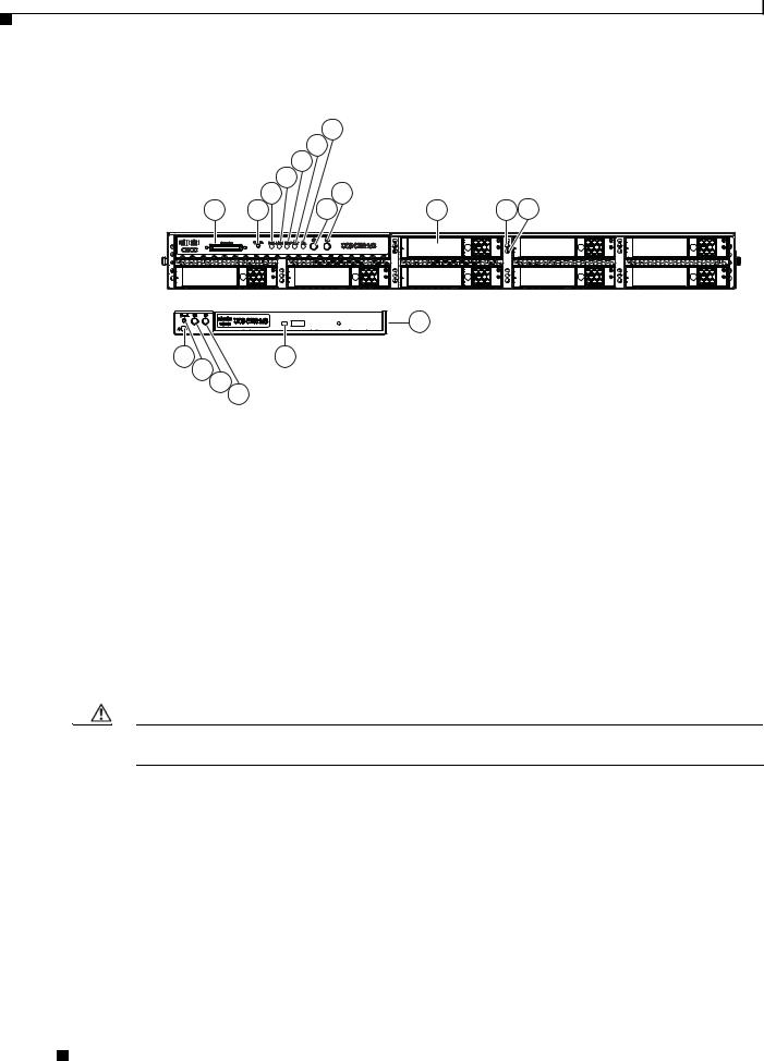
This server can be ordered with different front panel configurations, depending on whether the hard drives are the 3.5-inch large form factor or the 2.5-inch small form factor:
•Figure 1-1 shows the external features of the Large Form Factor (LFF) front panel.
•Figure 1-2 shows the external features of the Small Form Factor (SFF) front panel. The optional DVD module that can be configured in place of the front panel control module is also shown.
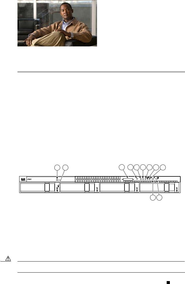
Figure 1-1 Front Panel Features, Large Form Factor
1 |
2 |
3 |
4 |
5 |
6 |
7 |
8 |
9 |
Console |
Reset |
PSU MEM CPU |
UCS C200 |
|
|
|
|
|
|
|
253036 |
|
|
10 |
11 |
1 |
DVD drive |
7 |
CPU fault LED |
|
|
|
|
2 |
Hard drive (up to four) |
8 |
Network activity LED |
|
|
|
|
3 |
KVM console connector |
9 |
System fault LED |
|
|
|
|
4 |
Reset button1 |
10 |
Locator button/LED |
5 |
Power supply fault LED |
11 |
Power button/Power status LED |
|
|
|
|
6 |
Memory fault LED |
|
|
|
|
|
|
1. See the following caution.
Caution Do not use the Reset button. This button is for development debugging only. This button will reset memory and CPU settings to the defaults.
Cisco UCS C200 Server Installation and Service Guide
|
OL-20732-02 |
1-1 |
|
|
|
Chapter 1 Overview
Figure 1-2 Front Panel Features, Small Form Factor
|
|
7 |
|
|
|
|
6 |
|
|
|
|
5 |
|
|
|
3 |
4 |
9 |
|
|
8 |
11 12 |
||
1 |
2 |
10 |
||
-A- |
|
|
13 |
|
|
|
|
|
|
18 |
|
14 |
|
|
17 |
|
|
|
|
16 |
15 |
|
|
310369 |
|
|
|
||
|
|
|
|
1 |
KVM console connector |
10 |
Hard drives (up to 8) |
|
|
|
|
2 |
Reset button1 |
11 |
Hard drive fault LED |
3 |
Power supply fault LED |
12 |
Hard drive activity LED |
|
|
|
|
4 |
Memory fault LED |
13 |
Optional DVD module |
|
|
|
|
5 |
CPU fault LED |
14 |
DVD activity LED |
|
|
|
|
6 |
Network activity LED |
15 |
Power button/Power status LED |
|
|
|
|
7 |
System fault LED |
16 |
Locator button/LED |
|
|
|
|
8 |
Locator button/LED |
17 |
Reset button2 |
9 |
Power button/Power status LED |
18 |
System fault LED |
|
|
|
|
1.See the following caution.
2.See the following caution.
Caution Do not use the Reset button. This button is for development debugging only. This button will reset memory and CPU settings to the defaults.
Cisco UCS C200 Server Installation and Service Guide
1-2 |
OL-20732-02 |
|
|
Chapter 1 Overview
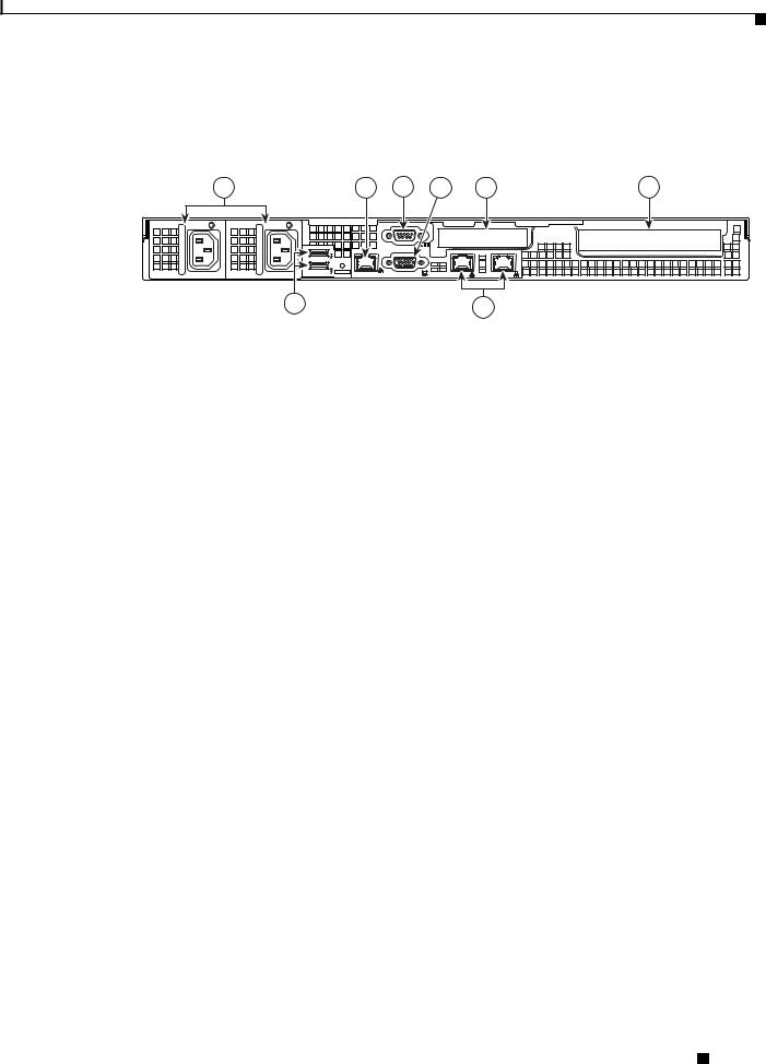
Figure 1-3 shows the external features of the rear panel. A Generation M2 server is shown (the USB ports and the 10/100 Ethernet management port are in slightly different positions for Generation M1).
Figure 1-3 Rear Panel Features
1 |
2 |
4 |
5 |
7 |
|
8 |
|
|
M |
|
|
|
253037 |
|
|
|
1/M |
|
2 |
|
|
3 |
|
|
6 |
|
|
1 |
Power supply (up to two) |
5 |
Video connector (DB15 VGA) |
|
|
|
|
2 |
10/100 Ethernet management port (RJ-45) |
6 |
10/100/1000 Gigabit Ethernet ports (two) |
|
|
|
|
3 |
USB 2.0 connectors (two) |
7 |
Low-profile PCIe card slot |
|
|
|
|
4 |
Serial connector (DB9) |
8 |
Standard-profile PCIe card slot |
|
|
|
|
Cisco UCS C200 Server Installation and Service Guide
|
OL-20732-02 |
1-3 |
|
|
|

Chapter 1 Overview
The Cisco UCS C200 server has the following components and features. Differences between the Large Form Factor (LFF) version of the server (PID R200-1120402W) and the Small Form Factor (SFF) version of the server (PID UCS-BSE-SFF-C200) are noted.
.
Table 1-1 |
Hardware Features of the Server |
|
||||
|
|
|
|
|
|
|
Feature or |
|
|
|
|
|
|
Component |
|
|
Cisco UCS C200 Server |
|
||
|
|
|
|
|
||
Enclosure |
|
|
Single rack unit (1RU) chassis. |
|
||
|
|
|
|
|
||
Processors |
|
|
Up to two quad-core Intel Xeon processors. |
|
||
|
|
|
|
|
||
Memory |
|
|
12 DIMM1 slots supporting up to 96 GB of industry-standard DDR32 main memory. |
|
||
Storage |
|
|
The number of drives depends on which configurable front panel you have: |
|
||
|
|
|
• LFF—Up to 4 internal 3.5-inch SAS3 or SATA4 drives. |
|
||
|
|
|
• SFF—Up to 8 internal 2.5-inch SAS or SATA drives. |
|
||
|
|
|
Server Generation M2 only—There is also one internal USB port on the |
|
||
|
|
|
motherboard that you can use with a USB thumb drive (see Figure 3-7). |
|
||
|
|
|
|
|
||
Network and |
|
|
The server provides these rear-panel connectors: |
|
||
management I/O |
|
• Two 10/100/1000 Gigabit Ethernet ports (RJ-45 connectors). |
|
|||
|
|
|
|
|||
|
|
|
|
These integrated Gigabit ports support the Wake on LAN (WoL) and TCP/IP |
|
|
|
|
|
|
Offload Engine (TOE) standards. |
|
|
|
|
|
• One 10/100 Ethernet port (RJ-45 connector). |
|
||
|
|
|
• One DB9 serial connector. |
|
||
|
|
|
• One DB15 VGA5 connector. |
|
||
|
|
|
• Two USB6 2.0 connectors. |
|
||
|
|
|
The server also has one front-panel console connector (with supplied KVM7 cable, |
|
||
|
|
|
provides DB15 video, DB9 serial, and two USB 2.0 connectors). |
|
||
|
|
|
|
|
|
|
|
|
|
Note The Cisco UCS C200 SFF server does not include a front-panel KVM |
|
||
|
|
|
|
|
connector if ordered with the optional DVD module. |
|
|
|
|
|
|
||
|
|
|
|
|||
Removable media |
|
One internal DVD drive: |
|
|||
devices |
|
|
• LFF—The DVD drive is not field-replaceable. |
|
||
|
|
|
|
|||
|
|
|
• SFF—The optional front panel DVD module is field-replaceable. |
|
||
|
|
|
The drive supports the following media types: CD-R, CD-ROM, CD-RW, DVD+R, |
|
||
|
|
|
DVD+RW, DVD-R, DVD-ROM, DVD-RW, +R DL |
|
||
|
|
|
|
|
||
Power |
|
|
Up to two power supplies, each with a maximum output of 650W (redundant power |
|
||
|
|
|
supply is optional). |
|
||
|
|
|
|
|||
Cooling |
|
Five internal fans that force front-to-rear cooling; also one fan in each power supply. |
|
|||
|
|
|
|
|
||
PCIe I/O |
|
|
Up to two PCIe8 expansion cards, plugged into horizontal riser card sockets: |
|
||
|
|
|
• One standard-profile, half-length, x16-lane, x16 connector (on riser card). |
|
||
|
|
|
• One low-profile, half-length, x8-lane, x8 connector (on riser card). |
|
||
|
|
|
|
|
|
|
Cisco UCS C200 Server Installation and Service Guide
1-4 |
OL-20732-02 |
|
|

Chapter 1 Overview
|
|
|
|
|
|
|
|
Table 1-1 |
Hardware Features of the Server (continued) |
|
|||||
|
|
|
|
|
|
|
|
Feature or |
|
|
|
|
|
|
|
Component |
|
Cisco UCS C200 Server |
|
||||
|
|
|
|
||||
Disk |
|
Factory-configured RAID9 support options, which differ for the LFF and SFF |
|
||||
Management |
|
versions of the server. |
|
||||
|
|
• |
LFF: |
|
|||
|
|
|
– RAID 0 and 1 support for up to 4 SATA drives with the integrated SATA |
|
|||
|
|
|
|
controller. |
|
||
|
|
|
|
|
|
|
|
|
|
|
Note The integrated ICH10R RAID controller is not compatible for use with |
|
|||
|
|
|
|
|
VMWare ESX/ESXi Server software in any generation or version of the |
|
|
|
|
|
|
|
Cisco UCS C200 server. |
|
|
|
|
|
|
|
|
||
|
|
|
– RAID 0, 1, and 1E support for up to 4 SAS or SATA drives with the optional |
|
|||
|
|
|
|
LSI 1064-based controller mezzanine card. |
|
||
|
|
|
– RAID 0, 1, 5, 6, 00, 10, 50 and 60 support for up to 4 SAS or SATA drives |
|
|||
|
|
|
|
with the optional LSI 9260-8i MegaRAID controller card. |
|
||
|
|
• |
SFF: |
|
|||
|
|
|
– RAID 0 and 1 support for up to 4 SATA drives with the integrated SATA |
|
|||
|
|
|
|
controller. |
|
||
|
|
|
|
|
|
|
|
|
|
|
Note The integrated ICH10R RAID controller is not compatible for use with |
|
|||
|
|
|
|
|
VMWare ESX/ESXi Server software in any generation or version of the |
|
|
|
|
|
|
|
Cisco UCS C200 server. |
|
|
|
|
|
|
|
|
||
|
|
|
– RAID 0, 1, and 1E support for up to 4 SAS or SATA drives with the optional |
|
|||
|
|
|
|
LSI 1068-based controller mezzanine card. |
|
||
|
|
|
– RAID 0, 1, 5, 6, 00, 10, 50 and 60 support for up to 8 SAS or SATA drives |
|
|||
|
|
|
|
with the optional LSI 9260-8i MegaRAID controller card. |
|
||
|
|
|
– RAID 0, 1, 5, 6, 00, 10, 50 and 60 support for up to 4 SAS or SATA drives |
|
|||
|
|
|
|
with the optional LSI 9280-4i4e MegaRAID controller card. |
|
||
|
|
See RAID Controller Considerations, page C-1 for more information about RAID in |
|
||||
|
|
this server. |
|
||||
|
|
|
|
||||
Video |
|
The server CIMC chip includes a Matrox G200 core. The Matrox G200 core shares |
|
||||
|
|
the same memory as the rest of the CIMC. The first 8 MB of memory are allocated |
|
||||
|
|
to the video core, followed by another 5 MB allocated to the compression engine for |
|
||||
|
|
difference buffers. |
|
||||
|
|
|
|
|
|
|
|
1.DIMM = dual inline memory module
2.DDR = double data rate (transfer mode)
3.SAS = serial attached SCSI
4.SATA = serial advanced technology attachment
5.VGA = video graphics array
6.USB = universal serial bus
7.KVM = keyboard, video, mouse
8.PCIe = peripheral component interconnect express
Cisco UCS C200 Server Installation and Service Guide
|
OL-20732-02 |
1-5 |
|
|
|

Chapter 1 Overview
9. RAID = redundant array of independent disks
See Appendix A, “Technical Specifications” for more physical, environmental, and power details.
Cisco UCS C200 Server Installation and Service Guide
1-6 |
OL-20732-02 |
|
|
C H A P T E R 2
Installing the Server
This chapter describes how to install the server and includes the following sections:
•Unpacking and Inspecting the Server, page 2-2
•Preparing for Installation, page 2-3
•Installing the Server Into a Rack, page 2-5
•Initial Server Setup, page 2-9
•System BIOS and CIMC Firmware, page 2-13
Note Before you install, operate, or service a server, review the Regulatory Compliance and Safety Information for Cisco UCS C-Series Servers for important safety information.
Warning IMPORTANT SAFETY INSTRUCTIONS
This warning symbol means danger. You are in a situation that could cause bodily injury. Before you work on any equipment, be aware of the hazards involved with electrical circuitry and be familiar with standard practices for preventing accidents. Use the statement number provided at the end of each warning to locate its translation in the translated safety warnings that accompanied this device.
Statement 1071
Warning Only trained and qualified personnel must be allowed to install, replace, or service this equipment.
Statement 1030
Cisco UCS C200 Server Installation and Service Guide
|
OL-20732-02 |
2-1 |
|
|
|
Chapter 2 Installing the Server
Unpacking and Inspecting the Server
Unpacking and Inspecting the Server
Tip Keep the shipping container in case the server requires shipping in the future.
Note The chassis is thoroughly inspected before shipment. If any damage occurred during transportation or any items are missing, contact your customer service representative immediately.
To inspect the shipment, follow these steps:
Step 1 Remove the server from its cardboard container—save all packaging material.
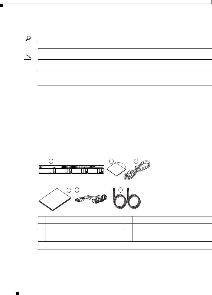
Step 2 Compare the shipment to the equipment list provided by your customer service representative and Figure 2-1. Verify that you have all items.
Step 3 Check for damage and report any discrepancies or damage to your customer service representative. Have the following information ready:
•Invoice number of shipper (see the packing slip)
•Model and serial number of the damaged unit
•Description of damage
•Effect of damage on the installation
Figure 2-1 Shipping Box Contents
1 |
2 |
3 |
Console |
Reset |
PSU MEM CPU |
UCS C200 |
UCS |
|
|
|
|
|
NexusCisco- |
|||
|
|
|
|
|||
|
|
|
|
|
C |
Series1010 |
|
|
|
|
|
|
|
|
4 |
5 |
6 |
|
|
UCS CCisco- |
|
|
|
|
Series |
|
|
|
|
|
|
|
197002 |
1 |
Server |
|
4 |
Documentation |
2 |
Drivers and Utilities disc |
5 |
KVM cable |
|
3 |
Power cord (up to two) |
6 |
C200 SFF server only: |
|
|
|
|
|
Two SAS cables (R200-SASCBL) |
Cisco UCS C200 Server Installation and Service Guide
2-2 |
OL-20732-02 |
|
|
Chapter 2 Installing the Server
Preparing for Installation
Preparing for Installation
This section includes the following topics:
•Installation Guidelines, page 2-3
•Rack Requirements, page 2-4
•Required Equipment, page 2-4
Installation Guidelines
Warning To prevent the system from overheating, do not operate it in an area that exceeds the maximum recommended ambient temperature of: 35° C (95° F).
Statement 1047
Warning The plug-socket combination must be accessible at all times, because it serves as the main disconnecting device.
Statement 1019
Warning This product relies on the building’s installation for short-circuit (overcurrent) protection. Ensure that the protective device is rated not greater than: 250 V, 15 A.
Statement 1005
Warning Installation of the equipment must comply with local and national electrical codes.
Statement 1074
When installing the server, follow these guidelines:
•Plan your site configuration and prepare the site before installing the server. See the Cisco UCS Site Preparation Guide for the recommended site planning tasks.
•Ensure that there is adequate space around the server to allow for servicing and for adequate airflow. The airflow in this server is from front to back.
•Ensure that the air-conditioning meets the thermal requirements listed in Appendix A, “Technical Specifications.”
•Ensure that the cabinet or rack meets the requirements listed in the “Rack Requirements” section on page 2-4.
•Ensure that the site power meets the power requirements listed in Appendix A, “Technical Specifications.” If available, you can use an uninterruptible power supply (UPS) to protect against power failures.
Caution Avoid UPS types that use ferroresonant technology. These UPS types can become unstable with systems such as the Cisco UCS, which can have substantial current draw fluctuations from fluctuating data traffic patterns.
Cisco UCS C200 Server Installation and Service Guide
|
OL-20732-02 |
2-3 |
|
|
|
Chapter 2 Installing the Server
Preparing for Installation
Rack Requirements
This section provides the requirements for the standard open racks, assuming an external ambient air temperature range of 32 to 95 F (0 to 35 C).
The rack must be of the following type:
•Standard 19-inch (48.3-cm) wide, four-post EIA rack, with mounting posts that conform to English universal hole spacing per section 1 of ANSI/EIA-310-D-1992.
•The rack post holes can be square or round when you use the supplied slide rails.
•The minimum vertical rack space per server must be one rack unit (RU), equal to 1.75 inches (4.45 cm).
•The distance between the front and rear rack posts must be as follows to fit the Cisco slide rails:
–For the older rails (R200-1032RAIL), 27 to 37 inches (68.6 to 94.0 cm)
–For the new style rails (R2XX-G31032RAIL), 23.5 to 36 inches (59.7 to 91.4 cm)
Tip The Cisco R-Series racks and RP-Series PDUs have been designed for optimum performance with Cisco products and are available from Cisco.
Required Equipment
The slide rails supplied by Cisco Systems do not require any tools for installation, but you might want to use a tape measure and level to help level the slide rails during installation.
Slide Rail Adjustment Range
The slide rails for this server have an adjustment range of 24 to 36 inches (610 to 914 mm).
Cisco UCS C200 Server Installation and Service Guide
2-4 |
OL-20732-02 |
|
|

Chapter 2 Installing the Server
Installing the Server Into a Rack
Installing the Server Into a Rack
The qualified and supported part numbers for this component are subject to change over time. For the most up-to-date list of replaceable components, see the following URL and then scroll to Technical Specifications:
http://www.cisco.com/en/US/products/ps10493/products_data_sheets_list.html
This section describes how to install the server into a rack.
Warning To prevent bodily injury when mounting or servicing this unit in a rack, you must take special precautions to ensure that the system remains stable. The following guidelines are provided to ensure your safety:
This unit should be mounted at the bottom of the rack if it is the only unit in the rack.
When mounting this unit in a partially filled rack, load the rack from the bottom to the top with the heaviest component at the bottom of the rack.
If the rack is provided with stabilizing devices, install the stabilizers before mounting or servicing the unit in the rack.
Statement 1006
To install the slide rails and the server into a rack, follow these steps:
Step 1 Install the slide rails into the rack:
Tip Use two people to help keep the slide rails and server level during installation. You can use a tape measure and level or count the holes in the rack posts to ensure that the slide rails and server are level.
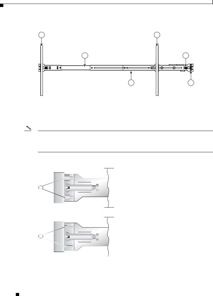
a.Align the slide-rail assembly inside the rack posts with the length-adjustment bracket (item 4) toward the rear of the rack (see Figure 2-2).
b.Compress the length-adjustment bracket until the mounting pegs (item 6) and locking clips (item 5) on the slide-rail assembly engage the desired rack holes on the front and rear rack posts.
If your rack has #10-32 rack-post holes, align the mounting pegs with the holes and then compress the spring-loaded pegs to expose the #10-32 inner peg.
Cisco UCS C200 Server Installation and Service Guide
|
OL-20732-02 |
2-5 |
|
|
|
Chapter 2 Installing the Server
Installing the Server Into a Rack
Figure 2-2 |
Attaching a Slide-Rail Assembly |
|
1 |
|
2 |
|
3 |
5 |
|
4 |
6 |
|
|
195968 |
1 |
Front-left rack post |
4 |
Length-adjustment bracket |
|
|
|
|
2 |
Rear-left rack post |
5 |
Locking clip (one on each end of assembly) |
|
|
|
|
3 |
Slide-rail assembly |
6 |
Mounting pegs (two on each end of assembly) |
|
|
|
|
Note The mounting pegs that protrude through the rack-post holes are designed to fit round or square #12-24 holes, or #10-32 holes when the mounting peg is compressed (see Figure 2-3). If your rack has #10-32 rack-post holes, align the mounting pegs with the holes and then compress the spring-loaded pegs to expose the #10-32 inner peg.
Figure 2-3 Spring-Loaded Mounting Pegs
1
2
|
|
330245 |
|
|
|
|
|
|
|
|
|
1 |
Pegs in standard (uncompressed) position |
2 |
Pegs compressed to expose 10-32 inner peg |
||
|
|
|
|
|
|
c.Pull the inner slide rails on each assembly out toward the rack front until they hit the internal stops and lock in place.
Cisco UCS C200 Server Installation and Service Guide
2-6 |
OL-20732-02 |
|
|
Chapter 2 Installing the Server
Installing the Server Into a Rack
d.Attach the second slide-rail assembly to the opposite side of the rack. Ensure that the two slide-rail assemblies are level and at the same height with each other.
e.Pull the inner slide rails on each assembly out toward the rack front until they hit the internal stops and lock in place.
Tip You can optionally use the #2 Phillips screws that come with the slide rails to increase stability after installation. These screws can be installed on the front attachment bracket on each assembly, but are not required.
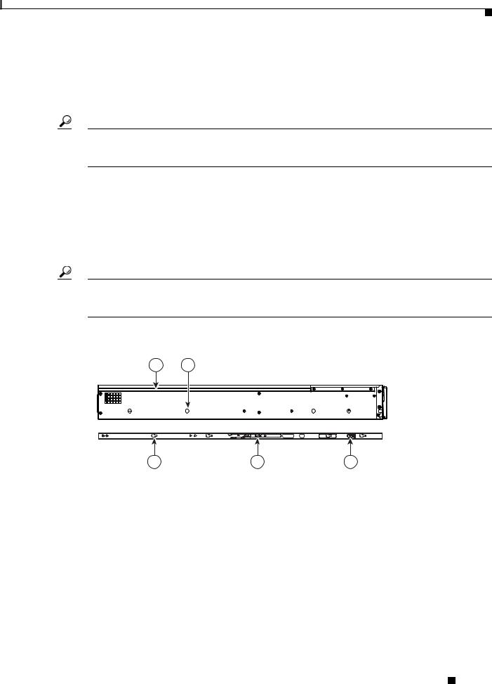
Step 2 Attach mounting brackets to the server:
a.Set a mounting bracket (item 3) on the side of the server, aligning its keyed holes over the pegs on the server (item 2). The plastic installation release clip (item 5) on the bracket should be toward the server front. See Figure 2-4.
b.Push the mounting bracket toward the server rear until the locking clip clicks over the server peg.
c.Attach the remaining mounting bracket to the opposite side of the server.
Tip You can optionally use the #1 Phillips screws that come with the slide rails to increase stability after installation. You can install two of these screws on each side of the server to more permanently attach the mounting brackets to each side of the server, but they are not required.
Figure 2-4 Attaching Mounting Brackets to the Server
1 |
2 |
|
195955 |
|
3 |
4 |
|
5 |
|
|
|
|
|
1 |
Rear of server |
|
4 |
Removal release clip |
|
|
|
|
|
2 |
Mounting peg (four) |
|
5 |
Installation release clip |
|
|
|
|
|
3 |
Mounting bracket |
|
|
|
|
|
|
|
|
Step 3 Insert the server into the slide rails:
a.Align the mounting brackets that are attached to the server sides with the front of the empty slide rails.
b.Push the server into the slide rails until it stops at the internal stops.
c.Push the plastic installation release clip on each mounting bracket toward the server rear (see item 4 in Figure 2-4), and then continue pushing the server into the rack until its front flanges touch the rack posts.
Cisco UCS C200 Server Installation and Service Guide
|
OL-20732-02 |
2-7 |
|
|
|
Chapter 2 Installing the Server
Installing the Server Into a Rack
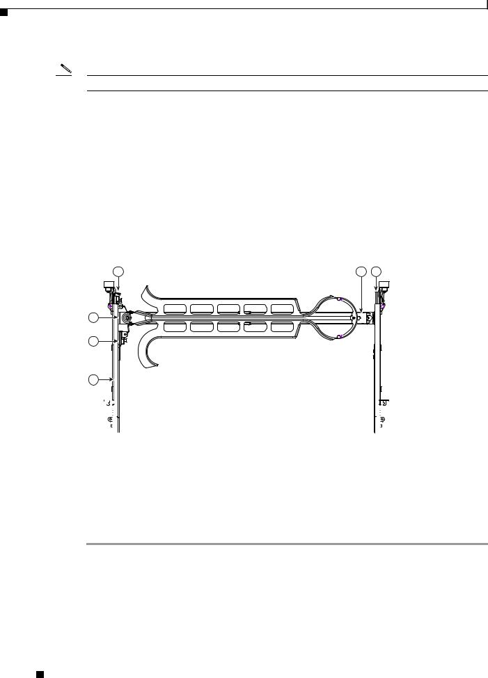
Step 4 Attach the (optional) cable management arm (CMA) to the rear of the slide rails:
Note The orientation in these instructions refers to a view from the front of the server.
a.Slide the plastic clip on the right end of the CMA length-adjustment slider (item 2) into the rear of the right slide rail (item 1) until it clips onto the plastic retaining flange inside the slide rail. See Figure 2-5.
b.Expand the CMA length-adjustment slider (item 2) until its left end aligns with the rear of the left slide-rail assembly (item 3).
c.Slide the innermost CMA attachment clip (item 4) into the rear of the left slide rail (item 3) and clip it onto the CMA flange that is on the mounting bracket that is attached to the server.
d.Attach the two-hole slotted bracket (item 5) that is on the left end of the CMA length-adjustment slider to the left slide rail. Fit the two-hole slotted bracket over the two pegs inside the slide rail.
e.Attach the outermost CMA attachment clip (item 6) onto the CMA flange that is on the left slide rail.
Figure 2-5 Attaching the Cable Management Arm
6 |
2 |
1 |
5
4
3
|
|
|
|
|
|
|
|
195969 |
|
|
|
|
|
|
|
|
|
|
|
|
|
|
|
|
|
|
|
|
|
|
|
|
|
|
|
1 |
Rear of right slide rail (plastic retaining flange |
4 |
Innermost CMA attachment clip |
|||||
|
is inside the rail) |
|
|
|
|
|||
|
|
|
|
|
|
|
|
|
2 |
CMA length-adjustment slider |
5 |
Two-hole slotted bracket on end of CMA |
|||||
|
|
|
|
|
|
length-adjustment slider |
||
|
|
|
|
|
|
|
|
|
3 |
Rear of left slide rail assembly |
6 |
Outermost CMA attachment clip |
|||||
|
|
|
|
|
|
|
|
|
Step 5 Continue with the “Connecting and Powering On the Server (Standalone Mode)” section on page 2-9.
Cisco UCS C200 Server Installation and Service Guide
2-8 |
OL-20732-02 |
|
|

Chapter 2 Installing the Server
Initial Server Setup
Initial Server Setup
This section contains the following topics:
•Connecting and Powering On the Server (Standalone Mode), page 2-9
•NIC Modes and NIC Redundancy Settings, page 2-12
Connecting and Powering On the Server (Standalone Mode)
Note This section describes how to power on the server, assign an IP address, and connect to server management when using the server in standalone mode. To use the server in UCS integration, specific cabling and settings are required. See Installation for Cisco UCS Integration, page D-1.
Note The server is shipped with a default NIC mode called Shared LOM, default NIC redundancy is active-active, and DHCP is enabled. Shared LOM mode enables the two 1-Gb Ethernet ports to access the Cisco Integrated Management Interface (CIMC). If you want to use the 10/100 management ports or a Cisco network adapter card port to access the CIMC, you must first connect to the server and change the NIC mode as described in Step 3 of the following procedure. In that step, you can also change the NIC redundancy and set static IP settings.
Use the following procedure to perform initial setup of the server.
Step 1 Attach a power cord to each power supply in your server, and then attach the power cord to a grounded AC power outlet. See the “Power Specifications” section on page A-2 for power specifications.
Wait for approximately two minutes to let the server boot in standby power during the first bootup.
You can verify power status by looking at the Power Status LED on the front panel (see Figure 1-1 on page 1-1 or Figure 1-2 on page 1-2):
•Off—The server is not receiving power. Check the power cord connections and the power source of the facility.
•Blinking green—The server is in standby power mode. Power is supplied only to the service processor and some motherboard functions.
•Solid green—The server is in main power mode. Power is supplied to all server components.
Note During bootup, the server beeps once for each USB device that is attached to the server. Even if there are no external USB devices attached, there is a short beep for each virtual USB device such as a virtual floppy drive, CD/DVD drive, keyboard, or mouse. A beep is also emitted if a USB device is hot-plugged or hot-unplugged during BIOS power-on self test (POST), or while you are accessing the BIOS Setup utility or the EFI shell.
Cisco UCS C200 Server Installation and Service Guide
|
OL-20732-02 |
2-9 |
|
|
|
Chapter 2 Installing the Server
Initial Server Setup
Step 2 Use the supplied KVM cable to connect a keyboard and VGA monitor to the console connector on the front panel (see Figure 1-1 on page 1-1 or Figure 1-2 on page 1-2).
Note Alternatively, you can use the VGA and USB ports on the rear panel. However, you cannot use the front panel console connector VGA and the rear panel VGA at the same time. If you are connected to one VGA connector and you then connect a video device to the other connector, the first VGA connector is disabled. You can then reactivate the first VGA connector only by rebooting the server.
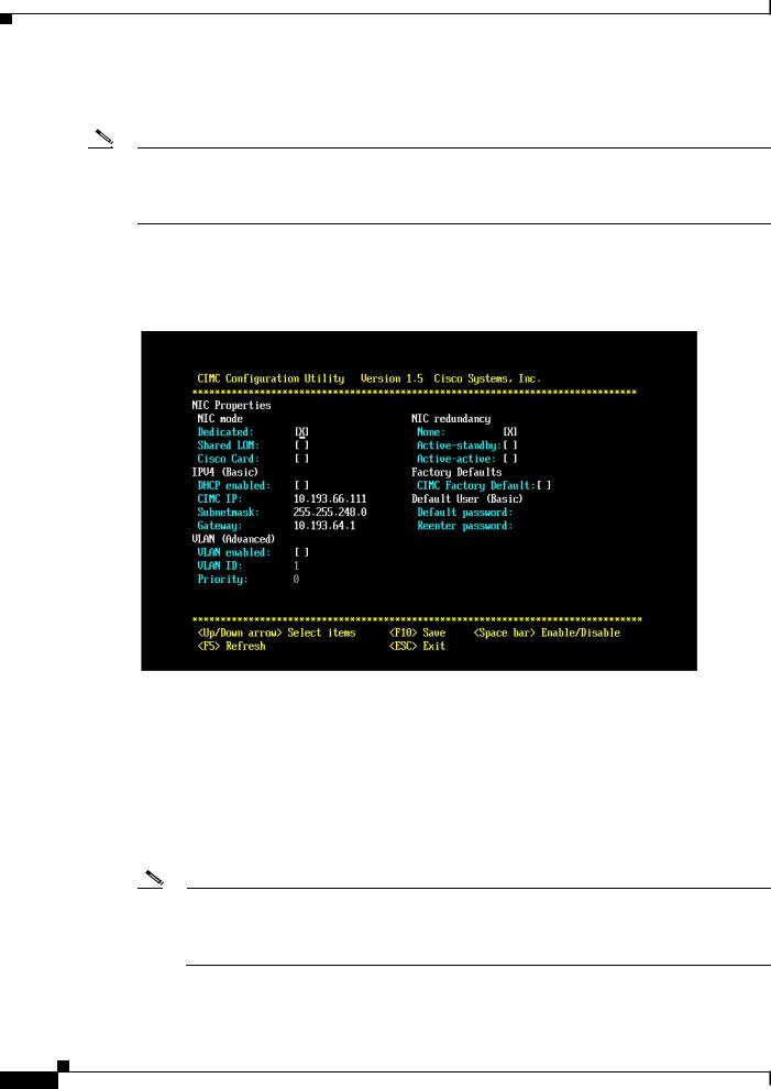
Step 3 Set NIC mode, NIC redundancy, and choose whether to enable DHCP or set static network settings:
a.Press the Power button to boot the server. Watch for the prompt to press F8.
b.During bootup, press F8 when prompted to open the BIOS CIMC Configuration Utility.
c.Set the NIC mode to your choice for which ports you want to use to access the CIMC for server management (see Figure 1-3 on page 1-3 for identification of the ports):
–Dedicated—The 10/100 management port is used to access the CIMC. You have to select a NIC redundancy and IP setting.
–Shared LOM (default)—The two 1Gb Ethernet ports are used to access the CIMC. This is the factory default setting, along with Active-active NIC redundancy and DHCP enabled.
–Cisco Card—The ports on an installed Cisco network adapter card are used to access the CIMC. You have to select a NIC redundancy and IP setting.
Note The Cisco Card NIC mode is currently supported only with a Cisco UCS P81E Virtual Interface Card (N2XX-ACPCI01) that is installed in PCIe slot 6 (see Figure 3-22 on page 3-36). See also Special Considerations for the Cisco UCS P81E Virtual Interface Card (N2XX-ACPCI01), page 3-37.
|
Cisco UCS C200 Server Installation and Service Guide |
2-10 |
OL-20732-02 |
 Loading...