


 Loading...
Configuring H.323 Gatekeepers and Proxies
This chapter describes how to configure the Cisco Multimedia Conference Manager. The Multimedia Conference Manager provides gatekeeper and proxy capabilities required for service provisioning and management of H.323-compliant networks.
This chapter includes the following sections:
•Multimedia Conference Manager Overview, page 289
•H.323 Gatekeeper Features, page 290
•H.323 Proxy Features, page 297
•H.323 Prerequisite Tasks and Restrictions, page 302
•H.323 Gatekeeper Configuration Task List, page 303
•H.323 Gatekeeper Configuration Examples, page 345
For a complete description of the H.323 gatekeeper commands used in this chapter, refer to the
Cisco IOS Voice, Video, and Fax Command Reference. To locate documentation for other commands that appear in this chapter, use the command reference master index or search online.
For more information regarding Resource Reservation Protocol (RSVP), synchronous reservation timers, and slow connect, refer to the Cisco IOS Release 12.1(5)T VoIP Call Admission Control Using RSVP or the Cisco IOS Quality of Service Solutions Configuration Guide.
To identify the hardware platform or software image information associated with a feature in this chapter, use the Feature Navigator on Cisco.com to search for information about the feature or refer to the software release notes for a specific release. For more information, see the “Identifying Supported Platforms” section in the “Using Cisco IOS Software” chapter.
Multimedia Conference Manager Overview
Deploying H.323 applications and services requires careful design and planning for the network infrastructure and for the H.323 devices. The Cisco H.323-compliant Multimedia Conference Manager provides gatekeeper and proxy capabilities, which are required for service provisioning and management of H.323 networks. With the Cisco Multimedia Conference Manager, your current internetwork can be configured to route bit-intensive data, such as audio, telephony, video and audio telephony, and data conferencing using existing telephone and ISDN links without degrading the current level of service of the network. In addition, H.323-compliant applications can be implemented on existing networks in an incremental fashion without upgrades.
Cisco IOS Voice, Video, and Fax Configuration Guide
VC-289

Configuring H.323 Gatekeepers and Proxies
H.323 Gatekeeper Features
Multimedia Conference Manager provides a rich list of networking capabilities, including the following:
•A means to implement quality of service (QoS), which is required for the successful deployment of H.323 applications.
•Interzone routing in the E.164 address space. When using H.323-identification (H.323-ID) format addresses, interzone routing is accomplished by using domain names.
Multimedia Conference Manager allows you to do the following:
•Identify H.323 traffic and apply appropriate policies.
•Limit H.323 traffic on the LAN and WAN.
•Provide user accounting for records based on service use.
•Insert QoS for the H.323 traffic generated by applications such as Voice over IP (VoIP), data conferencing, and video conferencing.
•Implement security for H.323 communications.
Principal Multimedia Conference Manager Functions
The H.323-compliant Multimedia Conference Manager has two principal functions: gatekeeper and proxy. Gatekeeper subsystems provide the following features:
•User authorization in which authentication, authorization, and accounting (AAA) account holders are permitted to register and use the services of the gatekeeper application.
•Accounting using AAA call detail records.
•Zone bandwidth management to limit the number of active sessions.
•H.323 call routing.
•Address resolution.
Cisco Multimedia Conference Managers can be configured to use the Cisco Hot Standby Router Protocol (HSRP) so that when one gatekeeper fails, the standby gatekeeper assumes its role.
Proxy subsystems provide the following features:
•H.323 traffic consolidation.
•Tight bandwidth controls.
•QoS mechanisms such as IP Precedence and RSVP.
•Secure communication over extranets.
H.323 Gatekeeper Features
The following sections describe the main features of a gatekeeper in an H.323 network:
•Zone and Subnet Configuration, page 291
•Redundant H.323 Zone Support, page 291
•Gatekeeper-to-Gatekeeper Redundancy and Load-Sharing Mechanism, page 292
•Interzone Communication, page 293
•RADIUS and TACACS+, page 293
•Accounting via RADIUS and TACACS+, page 293
Cisco IOS Voice, Video, and Fax Configuration Guide
VC-290

Configuring H.323 Gatekeepers and Proxies
H.323 Gatekeeper Features
•Interzone Routing Using E.164 Addresses, page 294
•HSRP Support, page 296
Zone and Subnet Configuration
A zone is defined as the set of H.323 nodes controlled by a single gatekeeper. Gatekeepers that coexist on a network may be configured so that they register endpoints from different subnets.
Endpoints attempt to discover a gatekeeper and consequently the zone of which they are members by using the Registration, Admission, and Status (RAS) message protocol. The protocol supports a discovery message that may be sent multicast or unicast.
If the message is sent multicast, the endpoint registers nondeterministically with the first gatekeeper that responds to the message. To enforce predictable behavior, where endpoints on certain subnets are assigned to specific gatekeepers, the zone subnet command can be used to define the subnets that constitute a given gatekeeper zone. Any endpoint on a subnet that is not enabled for the gatekeeper will not be accepted as a member of that gatekeeper zone. If the gatekeeper receives a discovery message from such an endpoint, it will send an explicit reject message.
Redundant H.323 Zone Support
Redundant H.323 zone support allows for the following:
•Gatekeeper Multiple Zone Support, page 291
•Gateway Support for Alternate Gatekeepers, page 291
•Zone Prefixes, page 291
•Technology Prefixes, page 292
Gatekeeper Multiple Zone Support
Redundant H.323 zone support allows users to configure multiple remote zones to service the same zone or technology prefix. A user is able to configure more than one remote gatekeeper to which the local gatekeeper can send location requests (LRQs). This allows for more reliable call completion.
Redundant H.323 zone support is supported on all gatekeeper-enabled IOS images.
Gateway Support for Alternate Gatekeepers
Redundant H.323 zone support in the gateway allows a user to configure two gatekeepers in the gateway (one as the primary and the other as the alternate). All gatekeepers are active. The gateway can choose to register with any one (but not both) at a given time. If that gatekeeper becomes unavailable, the gateway registers with the other.
Redundant H.323 zone support is supported on all gateway-enabled images.
Zone Prefixes
The zone prefixes (typically area codes) serve the same purpose as the domain names in the H.323-ID address space.
Cisco IOS Voice, Video, and Fax Configuration Guide
VC-291

Configuring H.323 Gatekeepers and Proxies
H.323 Gatekeeper Features
For example, the local gatekeeper can be configured with the knowledge that zone prefix “212......” (that is, any address beginning “212” and followed by 7 arbitrary digits) is handled by the gatekeeper gatekeeper_2. Then, when the local gatekeeper is asked to admit a call to destination address 2125551111, it knows to send the LRQ to gatekeeper_2.
When gatekeeper_2 receives the request, the gatekeeper must resolve the address so that the call can be sent to its final destination. There may be an H.323 endpoint with that E.164 address that has registered with gatekeeper_2, in which case gatekeeper_2 returns the IP address for that endpoint. However, it is possible that the E.164 address belongs to a non-H.323 device (for example, a telephone or an H.320 terminal). Because non-H.323 devices do not register with gatekeepers, gatekeeper_2 cannot resolve the address. The gatekeeper must be able to select a gateway that can be used to reach the non-H.323 device. This is where the technology prefixes (or “gateway-type”) become useful.
Technology Prefixes
The network administrator selects technology prefixes (tech-prefixes) to denote different types or classes of gateways. The gateways are then configured to register with their gatekeepers with these prefixes. For example, voice gateways can register with tech-prefix 1#, H.320 gateways with tech-prefix 2#, and voicemail gateways with tech-prefix 3#. More than one gateway can register with the same type prefix. When this happens, the gatekeeper makes a random selection among gateways of the same type.
If the callers know the type of device that they are trying to reach, they can include the technology prefix in the destination address to indicate the type of gateway to use to get to the destination. For example, if a caller knows that address 2125551111 belongs to a regular telephone, the destination address of 1#2125551111 can be used, where 1# indicates that the address should be resolved by a voice gateway. When the voice gateway receives the call for 1#2125551111, it strips off the technology prefix and bridges the next leg of the call to the telephone at 2125551111.
Gatekeeper-to-Gatekeeper Redundancy and Load-Sharing Mechanism
The gatekeeper-to-gatekeeper redundancy and load-sharing mechanism expands the capability that is provided by the redundant H.323 zone support feature. Redundant H.323 zone support, which was introduced in Cisco IOS Release 12.1(1)T, allows you to configure multiple gatekeepers to service the same zone or technology prefix by sending LRQs to two or more gatekeepers.
With the redundant H.323 zone support feature, the LRQs are sent simultaneously (in a “blast” fashion) to all of the gatekeepers in the list. The gateway registers with the gatekeeper that responds first. Then, if that gatekeeper becomes unavailable, the gateway registers with another gatekeeper from the list.
The gatekeeper-to-gatekeeper redundancy and load-sharing mechanism allows you to configure gatekeeper support and to give preference to specific gatekeepers. You may choose whether the LRQs are sent simultaneously or sequentially (one at a time) to the remote gatekeepers in the list. If the LRQs are sent sequentially, a delay is inserted after the first LRQ and before the next LRQ is sent. This delay allows the first gatekeeper to respond before the LRQ is sent to the next gatekeeper. The order in which LRQs are sent to the gatekeepers is based on the order in which the gatekeepers are listed (using either the zone prefix command or the gw-type-prefix command).
Once the local gatekeeper has sent LRQs to all the remote gatekeepers in the list (either simultaneously or sequentially), if it has not yet received a location confirmation (LCF), it opens a “window.” During this window, the local gatekeeper waits to see whether a LCF is subsequently received from any of the remote gatekeepers. If no LCF is received from any of the remote gatekeepers while the window is open, the call is rejected.
Cisco IOS Voice, Video, and Fax Configuration Guide
VC-292

Configuring H.323 Gatekeepers and Proxies
H.323 Gatekeeper Features
Terminal Name Registration
Gatekeepers recognize one of two types of terminal aliases, or terminal names:
•H.323 IDs, which are arbitrary, case-sensitive text strings
•E.164 addresses, which are telephone numbers
If an H.323 network deploys interzone communication, each terminal should at least have a fully qualified e-mail name as its H.323 identification (ID), for example, bob@cisco.com. The domain name of the e-mail ID should be the same as the configured domain name for the gatekeeper of which it is to be a member. As in the previous example, the domain name would be cisco.com.
Interzone Communication
To allow endpoints to communicate between zones, gatekeepers must be able to determine which zone an endpoint is in and be able to locate the gatekeeper responsible for that zone. If the Domain Name System (DNS) mechanism is available, a DNS domain name can be associated with each gatekeeper. See the DNS configuration task in the “Configuring Intergatekeeper Communication” section to understand how to configure DNS.
RADIUS and TACACS+
Version 1 of the H.323 specification does not provide a mechanism for authenticating registered endpoints. Credential information is not passed between gateways and gatekeepers. However, by enabling AAA on the gatekeeper and configuring for RADIUS and TACACS+, a rudimentary form of identification can be achieved.
If the AAA feature is enabled, the gatekeeper attempts to use the registered aliases along with a password and completes an authentication transaction to a RADIUS and TACACS+ server. The registration will be accepted only if RADIUS and TACACS+ successfully authenticates the name.
The gatekeeper can be configured so that a default password can be used for all users. The gatekeeper can also be configured so that it recognizes a password separator character that allows users to piggyback their passwords onto H.323-ID registrations. In this case, the separator character separates the ID and password fields.
Note The names loaded into RADIUS and TACACS+ are probably not the same names provided for dial access because they may all have the same password.
Accounting via RADIUS and TACACS+
If AAA is enabled on the gatekeeper, the gatekeeper will emit an accounting record each time a call is admitted or disconnected.
Cisco IOS Voice, Video, and Fax Configuration Guide
VC-293
Configuring H.323 Gatekeepers and Proxies
H.323 Gatekeeper Features
Interzone Routing Using E.164 Addresses
Interzone routing may be configured using E.164 addresses.
Two types of address destinations are used in H.323 calls. The destination can be specified using either an H.323-ID address (a character string) or an E.164 address (a string that contains telephone keypad characters). The way interzone calls are routed depends on the type of address being used.
When using H.323-ID addresses, interzone routing is handled through the use of domain names. For example, to resolve the domain name bob@cisco.com, the source endpoint gatekeeper finds the gatekeeper for cisco.com and sends it the location request for the target address bob@cisco.com. The destination gatekeeper looks in its registration database, sees bob registered, and returns the appropriate IP address to get to bob.
When using E.164 addresses, call routing is handled through zone prefixes and gateway-type prefixes, also referred to as technology prefixes. The zone prefixes, which are typically area codes, serve the same purpose as domain names in H.323-ID address routing. Unlike domain names, however, more than one zone prefix can be assigned to one gatekeeper, but the same prefix cannot be shared by more than one gatekeeper.
Use the zone prefix command to define gatekeeper responsibilities for area codes. The command can also be used to tell the gatekeeper which prefixes are in its own zones and which remote gatekeepers are responsible for other prefixes.
Note Area codes are used as an example in this section, but a zone prefix need not be an area code. It can be a country code, an area code plus local exchange (NPA-NXX), or any other logical hierarchical partition.
The following sample command shows how to configure a gatekeeper with the knowledge that zone prefix 212....... (that is, any address beginning with area code 212 and followed by seven arbitrary digits) is handled by gatekeeper gk-ny:
my-gatekeeper(config-gk)# zone prefix gk-ny 212.......
When my-gatekeeper is asked to admit a call to destination address 2125551111, it knows to send the location request to gk-ny.
However, once the query gets to gk-ny, gk-ny still needs to resolve the address so that the call can be sent to its final destination. There could be an H.323 endpoint that has registered with gk-ny with that E.164 address, in which case gk-ny would return the IP address for that endpoint. However, it is more likely that the E.164 address belongs to a non-H.323 device, such as a telephone or an H.320 terminal.
Because non-H.323 devices do not register with gatekeepers, gk-ny has no knowledge of which device the address belongs to or which type of device it is, so the gatekeeper cannot decide which gateway should be used for the hop off to the non-H.323 device. (The term hop off refers to the point at which the call leaves the H.323 network and is destined for a non-H.323 device.)
Note The number of zone prefixes defined for a directory gatekeeper that is dedicated to forwarding LRQs, and not for handling local registrations and calls, should not exceed 10,000; 4 MB of memory must be dedicated to describing zones and zone prefixes to support this maximum number of zone prefixes. The number of zone prefixes defined for a gatekeeper that handles local registrations and calls should not exceed 2000.
Cisco IOS Voice, Video, and Fax Configuration Guide
VC-294

Configuring H.323 Gatekeepers and Proxies
H.323 Gatekeeper Features
To enable the gatekeeper to select the appropriate hop-off gateway, use the gw-type-prefix command to configure technology or gateway-type prefixes. Select technology prefixes to denote different types or classes of gateways. The gateways are then configured to register with their gatekeepers using these technology prefixes.
For example, voice gateways might register with technology prefix 1#, and H.320 gateways might register with technology prefix 2#. If there are several gateways of the same type, configure them to register with the same prefix type. By having them register with the same prefix type, the gatekeeper treats the gateways as a pool out of which a random selection is made whenever a call for that prefix type arrives. If a gateway can serve more than one type of hop-off technology, it can register more than one prefix type with the gatekeeper.
Callers will need to know the technology prefixes that are defined. The callers will need to know the type of device they are trying to reach and will need to prepend the appropriate technology prefix to the destination address to indicate the type of gateway needed to reach the destination.
For example, callers might request 1#2125551111 if they know that address 2125551111 is for a telephone and that the technology prefix for voice gateways is 1#. The voice gateway is configured with a dial peer (using the dial-peer command) so that when the gateway receives the call for 1#2125551111, it strips off the technology prefix 1# and bridges the next leg of the call to the telephone at 2125551111.
In cases in which the call scenario is as shown in Figure 57, voice-gw1 can be configured to prepend the voice technology prefix 1# so that the use of technology prefixes is completely transparent to the caller.
Figure 57 |
Call Scenario |
|
|
||
PSTN |
|
|
H.323 network |
|
PSTN |
|
|
||||
Telephone |
voice-gw1 |
voice-gw2 |
Telephone |
13098
Additionally, in using the gw-type-prefix command, a particular gateway-type prefix can be defined as the default gateway type to be used for addresses that cannot be resolved. It also forces a technology prefix to always hop off in a particular zone.
If the majority of calls hop off on a particular type of gateway, the gatekeeper can be configured to use that type of gateway as the default type so that callers no longer have to prepend a technology prefix on the address. For example, if voice gateways are mostly used in a network, and all voice gateways have been configured to register with technology prefix 1#, the gatekeeper can be configured to use 1# gateways as the default technology if the following command is entered:
my-gatekeeper(config-gk)# gw-type-prefix 1# default-technology
Now a caller no longer needs to prepend 1# to use a voice gateway. Any address that does not contain an explicit technology prefix will be routed to one of the voice gateways that registered with 1#.
With this default technology definition, a caller could ask the gatekeeper for admission to 2125551111. If the local gatekeeper does not recognize the zone prefix as belonging to any remote zone, it will route the call to one of its local (1#) voice gateways so that the call hops off locally. However, if it knows that gk-ny handles the 212 area code, it can send a location request for 2125551111 to gk-ny. This requires that gk-ny also be configured with some default gateway type prefix and that its voice gateways be registered with that prefix type.
Cisco IOS Voice, Video, and Fax Configuration Guide
VC-295
Configuring H.323 Gatekeepers and Proxies
H.323 Gatekeeper Features
Note For ease of maintenance, the same prefix type should be used to denote the same gateway type in all zones under your administration. No more than 50 different technology prefixes should be registered per zone.
Also, with the gw-type-prefix command, a hop off can be forced to a particular zone. When an endpoint or gateway makes a call-admission request to its gatekeeper, the gatekeeper determines the destination address by first looking for the technology prefix. When that is matched, the remaining string is compared against known zone prefixes. If the address is determined to be a remote zone, the entire address, including technology and zone prefixes, is sent to the remote gatekeeper in a location request. That remote gatekeeper then uses the technology prefix to decide on which of its gateways to hop off. In other words, the zone prefix (defined using the zone prefix command) determines the routing to a zone, and once there, the technology prefix (defined using the gw-type-prefix command) determines the gateway to be used in that zone. The zone prefix takes precedence over the technology prefix.
This behavior can be overridden by associating a forced hop-off zone with a particular technology prefix. Associating a forced hop-off zone with a particular technology prefix forces the call to the specified zone, regardless of what the zone prefix in the address is. As an example, you are in the 408 area code and want callers to the 212 area code in New York to use H.323-over-IP and hop off there because it saves on costs. However, the only H.320 gateway is in Denver. In this example, calls to H.320 endpoints must be forced to hop off in Denver, even if the destination H.320 endpoint is in the 212 area code. The forced hop-off zone can be either a local zone (that is, one that is managed by the local gatekeeper) or a remote zone.
HSRP Support
Cisco routers support Hot Standby Router Protocol (HSRP), which allows one router to serve as a backup to another router. Cisco gatekeepers can be configured to use HSRP so that when one gatekeeper fails, the standby gatekeeper assumes its role.
To configure a gatekeeper to use HSRP, perform the following tasks:
•Select one interface on each gatekeeper to serve as the HSRP interface and configure these two interfaces so that they belong to the same HSRP group but have different priorities. The one with the higher priority will be the active gatekeeper; the other assumes the standby role. Make a note of the virtual HSRP IP address shared by both of these interfaces. (For details on HSRP and HSRP configuration, refer to the Cisco IOS IP Configuration Guide.)
•Configure the gatekeepers so that the HSRP virtual IP address is the RAS address for all local zones.
•Make sure that the gatekeeper-mode configurations on both routers are identical.
•If the endpoints and gateways are configured so that they use a specific gatekeeper address (rather than multicasting), use the HSRP virtual IP address as the gatekeeper address. You can also let the endpoints and gateways find the gatekeeper by multicasting. As long as it is on standby status, the secondary gatekeeper neither receives nor responds to multicast or unicast requests.
As long as both gatekeepers are up, the one with the higher priority on its HSRP interface will be the active gatekeeper. If this active gatekeeper fails, or if its HSRP interface fails, the standby HSRP interface assumes the virtual HSRP address and, with it, the active gatekeeper role. When the gatekeeper with the higher HSRP priority comes back online, it reclaims the HSRP virtual address and the gatekeeper function, while the secondary gatekeeper goes back to standby status.
Cisco IOS Voice, Video, and Fax Configuration Guide
VC-296

Configuring H.323 Gatekeepers and Proxies
H.323 Proxy Features
Note Gatekeeper failover will not be completely transparent to endpoints and gatekeepers. When the standby gatekeeper takes over, it does not have the state of the failed gatekeeper. If an endpoint that had registered with the failed gatekeeper now makes a request to the new gatekeeper, the gatekeeper responds with a reject, indicating that it does not recognize the endpoint. The endpoint must reregister with the new gatekeeper before it can continue H.323 operations.
For an example of configuring gatekeeper HSRP support, see the “H.323 Gatekeeper and Proxy Configuration Examples” section.
H.323 Proxy Features
Each of the following sections describes how the proxy feature can be used in an H.323 network:
•Security, page 297
•Quality of Service, page 301
•Application-Specific Routing, page 301
Security
When terminals signal each other directly, they must have direct access to each other’s addresses. This exposes an attacker to key information about a network. When a proxy is used, the only addressing information that is exposed to the network is the address of the proxy; all other terminal and gateway addresses are hidden.
There are several ways to use a proxy with a firewall to enhance network security. The configuration to be used depends on how capable the firewall is of handling the complex H.323 protocol suite. Each of the following sections describes a common configuration for using a proxy with a firewall:
•Proxy Inside the Firewall, page 298
•Proxy in Co-Edge Mode, page 299
•Proxy Outside the Firewall, page 300
•Proxies and NAT, page 300
Cisco IOS Voice, Video, and Fax Configuration Guide
VC-297
Configuring H.323 Gatekeepers and Proxies
H.323 Proxy Features
Proxy Inside the Firewall
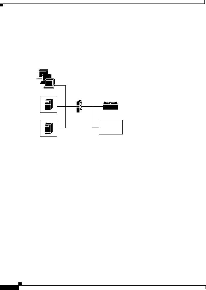
H.323 is a complex, dynamic protocol that consists of several interrelated subprotocols. During H.323 call setup, the ports and addresses released with this protocol require a detailed inspection as the setup progresses. If the firewall does not support this dynamic access control based on the inspection, a proxy can be used just inside the firewall. The proxy provides a simple access control scheme, as illustrated in Figure 58.
Figure 58 Proxy Inside the Firewall
Terminals
Edge router
Gatekeeper |
Firewall |
Outside devices
Proxy
S6913
Because the gatekeeper (using RAS) and the proxy (using call setup protocols) are the only endpoints that communicate with other devices outside the firewall, it is simple to set up a tunnel through the firewall to allow traffic destined for either of these two endpoints to pass through.
Cisco IOS Voice, Video, and Fax Configuration Guide
VC-298

Configuring H.323 Gatekeepers and Proxies
H.323 Proxy Features
Proxy in Co-Edge Mode
If H.323 terminals exist in an area with local interior addresses that must be translated to valid exterior addresses, the firewall must be capable of decoding and translating all addresses passed in the various H.323 protocols. If the firewall is not capable of this translation task, a proxy may be placed next to the firewall in a co-edge mode. In this configuration, interfaces lead to both inside and outside networks.
(See Figure 59.)
Figure 59 Proxy in Co-Edge Mode
Firewall
Terminals |
Gatekeeper |
Proxy
Edge router
Outside devices
S6914
In co-edge mode, the proxy can present a security risk. To avoid exposing a network to unsolicited traffic, configure the proxy to route only proxied traffic. In other words, the proxy routes only H.323 protocol traffic that is terminated on the inside and then repeated to the outside. Traffic that moves in the opposite direction can be configured this way as well.
Cisco IOS Voice, Video, and Fax Configuration Guide
VC-299

Configuring H.323 Gatekeepers and Proxies
H.323 Proxy Features
Proxy Outside the Firewall
To place the proxy and gatekeeper outside the firewall, two conditions must exist. First, the firewall must support H.323 dynamic access control. Second, Network Address Translation (NAT) must not be in use.
If NAT is in use, each endpoint must register with the gatekeeper for the duration of the time it is online. This will quickly overwhelm the firewall because a large number of relatively static, internal-to-external address mappings will need to be maintained.
If the firewall does not support H.323 dynamic access control, the firewall can be configured with static access lists that allow traffic from the proxy or gatekeeper through the firewall. This can present a security risk if an attacker can spoof, or simulate, the IP addresses of the gatekeeper or proxy and use them to attack the network. Figure 60 illustrates proxy outside the firewall.
Figure 60 Proxy Outside the Firewall
Edge router
Gatekeeper
Terminals Firewall
Proxy
Outside devices
S6915
Proxies and NAT
When a firewall is providing NAT between an internal and an external network, proxies may allow H.323 traffic to be handled properly, even in the absence of a firewall that can translate addresses for H.323 traffic. Table 24 and Table 25 provide guidelines for proxy deployment for networks that use NAT.
Table 24 |
Guidelines for Networks That Use NAT |
|
|
|
|
|
|
For Networks Using NAT |
Firewall with H.323 NAT |
Firewall Without H.323 NAT |
|
|
|
|
|
Firewall with dynamic access |
Gatekeeper and proxy inside the |
Co-edge gatekeeper and proxy |
|
control |
|
firewall |
|
|
|
|
|
Firewall without dynamic access |
Gatekeeper and proxy inside the |
Co-edge gatekeeper and proxy |
|
control |
|
firewall, with static access lists |
|
|
|
on the firewall |
|
|
|
|
|
Cisco IOS Voice, Video, and Fax Configuration Guide
VC-300

Configuring H.323 Gatekeepers and Proxies
H.323 Proxy Features
Table 25 |
Guidelines for Networks That Do Not Use NAT |
|
|
|
|
|
|
For Networks Not Using NAT |
Firewall with H.323. NAT |
Firewall Without H.323 NAT |
|
|
|
|
|
Firewall with Dynamic Access |
Gatekeeper and proxy inside the |
Gatekeeper and proxy inside the |
|
Control |
|
firewall |
firewall |
|
|
Gatekeeper and proxy outside |
Gatekeeper and proxy outside the |
|
|
the firewall |
firewall |
|
|
|
|
Firewall Without Dynamic |
Gatekeeper and proxy inside the |
Gatekeeper and proxy inside the |
|
Access Control |
firewall, with static access lists |
firewall, with static access lists |
|
|
|
on the firewall |
on the firewall |
|
|
|
|
Quality of Service
Quality of service (QoS) enables complex networks to control and predictably service a variety of applications. QoS expedites the handling of mission-critical applications while sharing network resources with noncritical applications. QoS also ensures available bandwidth and minimum delays required by time-sensitive multimedia and voice applications. In addition, QoS gives network managers control over network applications, improves cost-efficiency of WAN connections, and enables advanced differentiated services. QoS technologies are elemental building blocks for other Cisco IOS-enabling services such as its H.323-compliant gatekeeper. Overall call quality can be improved dramatically in the multimedia network by using pairs of proxies between regions of the network where QoS can be requested.
When two H.323 terminals communicate directly, the resulting call quality can range from good (for high-bandwidth intranets) to poor (for most calls over the public network). As a result, deployment of H.323 is almost always predicated on the availability of some high-bandwidth, low-delay, low-packet-loss network that is separate from the public network or that runs overlaid with the network as a premium service and adequate QoS.
Adequate QoS usually requires terminals that are capable of signaling such premium services. There are two major ways to achieve such signaling:
•RSVP to reserve flows having adequate QoS based on the media codecs of H.323 traffic
•IP precedence bits to signal that the H.323 traffic is special and that it deserves higher priority Unfortunately, the vast majority of H.323 terminals cannot achieve signaling in either of these ways. The proxy can be configured to use any combination of RSVP and IP precedence bits.
The proxy is not capable of modifying the QoS between the terminal and itself. To achieve the best overall QoS, ensure that terminals are connected to the proxy using a network that intrinsically has good QoS. In other words, configure a path between a terminal and proxy that provides good bandwidth, delay, and packet-loss characteristics without the terminal needing to request special QoS. A high-bandwidth LAN works well for this.
Application-Specific Routing
To achieve adequate QoS, a separate network may be deployed that is partitioned away from the standard data network. The proxy can take advantage of such a partitioned network using a feature known as application-specific routing (ASR).
Cisco IOS Voice, Video, and Fax Configuration Guide
VC-301

Configuring H.323 Gatekeepers and Proxies
H.323 Prerequisite Tasks and Restrictions
Application-specific routing is simple. When the proxy receives outbound traffic, it directs traffic to an interface that is connected directly to the QoS network. The proxy does not send the traffic using an interface that is specified for the regular routing protocol. Similarly, inbound traffic from other proxies is received on the interface that is connected to the QoS network. This is true if all these other proxies around the QoS network use ASR in a consistent fashion. ASR then ensures that ordinary traffic is not routed into the QoS network by mistake.
Implementation of ASR ensures the following:
•Each time a connection is established with another proxy, the proxy automatically installs a host route pointing at the interface designated for ASR.
•The proxy is configured to use a loopback interface address. The proxy address is visible to both the ASR interface and all regular interfaces, but there are no routes established between the loopback interface and the ASR interface. This ensures that no non-H.323 traffic is routed through the ASR interface.
Note ASR is not supported on Frame Relay or ATM interfaces for the Cisco MC3810 platform.
H.323 Prerequisite Tasks and Restrictions
This section contains prerequisite tasks and restrictions for configuring H.323 gatekeepers and proxies.
Redundant H.323 Zone Support
Redundant H.323 zone support has the following restrictions and limitations:
•The gateway can register with only one gatekeeper at any given time.
•Only E.164 address resolution is supported.
•Because the gateway can register with only one gatekeeper at a time, redundant H.323 zone support provides only redundancy and does not provide any load balancing.
•Although redundant H.323 zone support allows you to configure alternate gatekeepers, it will not insert information in the alternate gatekeeper field of some RAS messages.
Gatekeeper-to-Gatekeeper Redundancy and Load-Sharing Mechanism
The gatekeeper-to-gatekeeper redundancy and load-sharing mechanism has the following restrictions and limitations:
•The gatekeeper-to-gatekeeper redundancy and load-sharing mechanism requires the Cisco H.323 VoIP Gatekeeper for Cisco Access Platforms feature.
•The order in which LRQs are sent to the gatekeepers is based on the order in which the gatekeepers are listed. You cannot specify a priority number for a gatekeeper.
•Regardless of the order in which the LRQs are sent, the gateway will still use the first gatekeeper that sends an LCF.
•The settings for delay between LRQs and the LRQ window are global and cannot be set on a per-zone or technology-prefix basis.
Cisco IOS Voice, Video, and Fax Configuration Guide
VC-302

Configuring H.323 Gatekeepers and Proxies
H.323 Gatekeeper Configuration Task List
•The number of remote gatekeepers multiplied by the delay per LRQ cannot exceed the Routing Information Protocol (RIP) timeout. Therefore, we recommend that you limit your list of remote gatekeepers to two or three.
•If LRQ forwarding is enabled on the directory gatekeeper, the sequential setting for LRQs is ignored.
•Only E.164 address resolution is supported.
•Using redundant H.323 zone support in the “directory gatekeeper” can generate extra RAS messages. Therefore, the number of “directory gatekeeper” levels should be kept to a minimum (two or three at the maximum).
H.323 Gatekeeper Configuration Task List
To configure Cisco gatekeepers, perform the tasks in the following sections. The tasks in these two sections are required.
•Configuring the Gatekeeper, page 303 (Required)
•Configuring the Proxy, page 332 (Required)
Configuring the Gatekeeper
To configure gatekeepers, perform the tasks in the following sections. All of the tasks listed are required.
•Starting a Gatekeeper, page 304
–Configuring Intergatekeeper Communication, page 307
•Configuring Redundant H.323 Zone Support, page 308
•Configuring Local and Remote Gatekeepers, page 309
•Configuring Redundant Gatekeepers for a Zone Prefix, page 310
•Configuring Redundant Gatekeepers for a Technology Prefix, page 311
•Configuring Static Nodes, page 313
•Configuring H.323 Users via RADIUS, page 314
•Configuring a RADIUS/AAA Server, page 318
•Configuring User Accounting Activity for RADIUS, page 320
•Configuring E.164 Interzone Routing, page 321
•Configuring H.323 Version 2 Features, page 322
–Configuring a Dialing Prefix for Each Gateway, page 323
–Configuring a Prefix to a Gatekeeper Zone List, page 326
–Configuring a Gatekeeper for Interaction with External Applications, page 325
–Configuring Gatekeeper Triggers for Interaction with External Applications, page 327
–Configuring Redundant H.323 Zone Support, page 308
–Configuring a Forced Disconnect on a Gatekeeper, page 332
Cisco IOS Voice, Video, and Fax Configuration Guide
VC-303

Configuring H.323 Gatekeepers and Proxies
H.323 Gatekeeper Configuration Task List
Starting a Gatekeeper
To enter gatekeeper configuration mode and to start the gatekeeper, use the following commands beginning in global configuration mode:
|
Command |
Purpose |
Step 1 |
|
|
Router(config)# gatekeeper |
Enters gatekeeper configuration mode. |
|
Step 2 |
|
|
Router(config-gk)# zone local gatekeeper-name |
Specifies a zone controlled by a gatekeeper. |
|
|
domain-name [ras-IP-address] |
The arguments are as follows: |
|
|
|
|
|
• gatekeeper-name—Specifies the gatekeeper |
|
|
name or zone name. This is usually the fully |
|
|
domain-qualified host name of the gatekeeper. |
|
|
For example, if the domain name is cisco.com, |
|
|
the gatekeeper name might be gk1.cisco.com. |
|
|
However, if the gatekeeper is controlling |
|
|
multiple zones, the gatekeeper name for each |
|
|
zone should be some unique string that has a |
|
|
mnemonic value. |
|
|
• domain-name—Specifies the domain name |
|
|
served by this gatekeeper. |
|
|
• ras-IP-address—(Optional) Specifies the IP |
|
|
address of one of the interfaces on the |
|
|
gatekeeper. When the gatekeeper responds to |
|
|
gatekeeper discovery messages, it signals the |
|
|
endpoint or gateway to use this address in future |
|
|
communications. |
|
|
Note Setting this address for one local zone makes |
|
|
it the address used for all local zones. |
|
|
|
Cisco IOS Voice, Video, and Fax Configuration Guide
VC-304

Configuring H.323 Gatekeepers and Proxies
H.323 Gatekeeper Configuration Task List
|
Command |
Purpose |
|
|
|
Step 3 Router(config-gk)# zone prefix gatekeeper-name |
Adds a prefix to the gatekeeper zone list. |
|
|
e164-prefix [blast | seq] [gw-priority priority |
The keywords and arguments are as follows: |
|
gw-alias [gw-alias, ...]] |
|
|
|
• gatekeeper-name—Specifies the name of a local |
|
|
or remote gatekeeper, which must have been |
|
|
defined by using the zone local or zone remote |
|
|
command. |
|
|
• e164-prefix—Specifies an E.164 prefix in |
|
|
standard form followed by dots (.). Each dot |
|
|
represents a number in the E.164 address. For |
|
|
example, 212....... is matched by 212 and any 7 |
|
|
numbers. |
|
|
Note Although a dot to represent each digit in an |
|
|
E.164 address is the preferred configuration |
|
|
method, you can also enter an asterisk (*) to |
|
|
match any number of digits. |
|
|
• blast—(Optional) If you list multiple hopoffs, |
|
|
indicates that the location requests (LRQs) |
|
|
should be sent simultaneously to the gatekeepers |
|
|
based on the order in which they were listed. The |
|
|
default is seq. |
|
|
• seq—(Optional) If you list multiple hopoffs, |
|
|
indicates that the LRQs should be sent |
|
|
sequentially to the gatekeepers based on the |
|
|
order in which they were listed. The default is |
|
|
seq. |
|
|
• gw-priority priority gw-alias—(Optional) Use |
|
|
the gw-priority option to define how the |
|
|
gatekeeper selects gateways in its local zone for |
|
|
calls to numbers that begin with prefix |
|
|
e164-prefix. Do not use this option to set priority |
|
|
levels for a prefix assigned to a remote |
|
|
gatekeeper. |
|
|
Use values from 0 to 10. A 0 value prevents the |
|
|
gatekeeper from using the gateway gw-alias for |
|
|
that prefix. Value 10 places the highest priority |
|
|
on gateway gw-alias. If you do not specify a |
|
|
priority value for a gateway, the value 5 is |
|
|
assigned. |
|
|
To assign the same priority value for one prefix |
|
|
to multiple gateways, list all the gateway names |
|
|
after the pri-0-to-10 value. |
|
|
The gw-alias name is the H.323 ID of a gateway |
|
|
that is registered or will register with the |
|
|
gatekeeper. This name is set on the gateway with |
|
|
the h323-gateway voip h.323-id command. |
|
|
|
Cisco IOS Voice, Video, and Fax Configuration Guide
VC-305

Configuring H.323 Gatekeepers and Proxies
H.323 Gatekeeper Configuration Task List
|
Command |
Purpose |
Step 4 |
Router(config-gk)# zone subnet local-gatekeeper-name |
Defines a set of subnets that constitute the gatekeeper |
|
[default | subnet-address {/bits-in-mask | |
zone. Enables the gatekeeper for each of these |
|
mask-address} enable] |
subnets and disables it for all other subnets. (Repeat |
|
|
|
|
|
for all subnets.) |
|
|
The keywords and arguments are as follows: |
|
|
• local-gatekeeper-name—Specifies the name of |
|
|
the local gatekeeper. |
|
|
• default—(Optional) Applies to all other subnets |
|
|
that are not specifically defined by the |
|
|
zone subnet command. |
|
|
• subnet-address—(Optional) Specifies the |
|
|
address of the subnet that is being defined. |
|
|
• bits-in-mask—(Optional) Specifies the number |
|
|
of bits of the mask to be applied to the subnet |
|
|
address. |
|
|
Note The slash must be entered before this |
|
|
argument. |
|
|
• mask-address—(Optional) Specifies the mask (in |
|
|
dotted string format) to be applied to the subnet |
|
|
address. |
|
|
• enable—(Optional) Specifies that the gatekeeper |
|
|
accepts discovery and registration from the |
|
|
specified subnets. |
|
|
Note To define the zone as being all but one set of |
|
|
subnets by disabling that set and enabling all |
|
|
other subnets, use the no form of the |
|
|
command as follows: Configure no zone |
|
|
subnet local-gatekeeper-name |
|
|
subnet-address {/bits-in-mask | |
|
|
mask-address} enable. |
Note To accept the default behavior, which is that all subnets are enabled, use the no form of the command as follows: no zone subnet local-gatekeeper-name default enable.
Step 5 |
Router(config-gk)# no shutdown |
Brings the gatekeeper online. |
The local-gatekeeper-name argument should be a Domain Name System (DNS) host name if DNS is to be used to locate remote zones.
The zone subnet command may be used more than once to create a list of subnets controlled by a gatekeeper. The subnet masks need not match actual subnets in use at your site. For example, to specify a particular endpoint, show its address as a 32-bit netmask.
If a local gatekeeper name is contained in the message, it must match the local-gatekeeper-name argument.
Cisco IOS Voice, Video, and Fax Configuration Guide
VC-306
Configuring H.323 Gatekeepers and Proxies
H.323 Gatekeeper Configuration Task List
Note To explicitly enable or disable a particular endpoint, specify its host address using a 32-bit subnet mask.
Configuring Intergatekeeper Communication
This section describes two ways to configure intergatekeeper communication:
•Via DNS, page 307
•Manual Configuration, page 308
Via DNS
To configure intergatekeeper communication using DNS, use the following commands in global configuration mode:
|
Command |
Purpose |
Step 1 |
|
|
Router(config)# ip name-server dns-server-name |
Specifies the DNS server address. |
|
|
[server-address2...server-address6] |
The arguments are as follows: |
|
|
|
|
|
• dns-server-name— Specifies the IP address of |
|
|
the name server. |
|
|
• server-address2...server-address6—(Optional) |
|
|
IP addresses of additional name servers (a |
|
|
maximum of six name servers). |
Step 2 |
|
|
Router(config)# ip domain-name name |
Defines a default domain name that the Cisco IOS |
|
|
|
software uses to complete unqualified host names |
|
|
(names without a dotted-decimal domain name). The |
|
|
name argument specifies the default domain name |
|
|
used to complete unqualified host names. Do not |
|
|
include the initial period that separates an unqualified |
|
|
name from the domain name. |
|
|
|
For all gatekeepers in the system, enter a text record of the form into DNS:
ras [gk-id@] host [:port] [priority]
The gk-id argument is an optional gatekeeper ID. If the optional gatekeeper ID is not specified, host is used as the gatekeeper ID.
The host argument is either an IP address or the actual host name of the gatekeeper in the form host.some_domain.com.
The port argument, if specified, should be some port number other than RAS port 1719.
The priority argument specifies the order in which the listed gatekeepers should be searched for endpoints. Gatekeepers with lower priorities are searched before those with higher numbers.
How you enter the text record for a particular domain depends on the DNS implementation. The following examples are for the Berkeley Internet Name Domain (BIND). These records are typically entered into the “hosts” database:
zone1.comintxt“ras gk.zone1.com” zone2.comintxt“ras gk2@gk.zone2.com”
Cisco IOS Voice, Video, and Fax Configuration Guide
VC-307

Configuring H.323 Gatekeepers and Proxies
H.323 Gatekeeper Configuration Task List
zone3.comintxt“ras gk.3@gk.zone3.com:1725” zone4.comintxt“ras gk4@gk.zone4.com:1725 123” zone5.comintxt“ras gk5@101.0.0.1:1725”
Manual Configuration
If you choose not to use DNS or if DNS is not available, configure intergatekeeper communication manually. To configure intergatekeeper manual communication, use the following command in gatekeeper configuration mode for every other gatekeeper in the network:
Command |
Purpose |
|
|
Router(config-gk)# zone remote other-gatekeeper-name |
Statically specifies a remote zone if Domain Name System |
other-domain-name other-gatekeeper-ip-address |
(DNS) is unavailable or undesirable. Enter this command |
[port-number] |
for each gatekeeper. |
|
|
|
The arguments are as follows: |
|
• other-gatekeeper-name—Specifies the name of the |
|
remote gatekeeper. |
|
• other-domain-name—Specifies the domain name of |
|
the remote gatekeeper. |
|
• other-gatekeeper-ip-address—Specifies the IP |
|
address of the remote gatekeeper. |
|
• port-number—(Optional) Specifies the RAS signaling |
|
port number for the remote zone. Value ranges are |
|
from 1 to 65,535. If this option is not set, the default is |
|
the well-known RAS port number 1719. |
|
|
Configuring Redundant H.323 Zone Support
Regardless of whether you specify sequential or blast, there is an order to how the LRQs are sent. With sequential, the LRQs are sent one at a time with a delay between each. With blast, the LRQs are sent back-to-back in a rapid sequence without any delay between them. The order in which zone and technology prefixes are configured determines the order in which the LRQs are sent to the remote gatekeepers. Using zone prefixes as an example, the local gatekeeper routes the call to the first zone that responds with an LCF. If the local gatekeeper is configured for a zone prefix that already has remote gatekeepers configured, the local gatekeeper will automatically put that zone prefix at the top of the list.
For example:
gatekeeper
zone local gnet-2503-2-gk cisco.com
zone remote gnet-2600-1-gk cisco.com 172.18.194.131 1719 zone remote gnet-2503-3-gk cisco.com 172.18.194.134 1719 zone prefix gnet-2600-1-gk 919.......
zone prefix gnet-2503-6-gk 919.......
With this configuration, LRQs are first sent to gnet-2600-1-gk (which is the first zone prefix because it has a remote gatekeeper configured for it) and then to gnet-2503-6-gk (which is the second zone prefix). If you add the local gatekeeper to that zone prefix, it automatically goes to the top of the list, as shown below:
gatekeeper
zone local gnet-2503-2-gk cisco.com
zone remote gnet-2600-1-gk cisco.com 172.18.194.131 1719
Cisco IOS Voice, Video, and Fax Configuration Guide
VC-308
Configuring H.323 Gatekeepers and Proxies
H.323 Gatekeeper Configuration Task List
zone remote gnet-2503-3-gk cisco.com 172.18.194.134 1719
zone prefix gnet-2503-2-gk 919.......
zone prefix gnet-2600-1-gk 919.......
zone prefix gnet-2503-6-gk 919.......
As you can see, the zone prefix for the local gatekeeper (gnet-2503-2-gk) has been inserted at the top of the zone prefix list. If the local gatekeeper can resolve the address, it will not send LRQs to the remote zones.
If you are configuring technology prefixes, the zone prefix for the local gatekeeper should be inserted at the top of the zone prefix list. If the local gatekeeper can resolve the address, it will not send LRQs to the remote zones.
Configuring Local and Remote Gatekeepers
To configure local and remote gatekeepers, use the following commands beginning in global configuration mode:
|
Command |
Purpose |
Step 1 |
|
|
Router(config)# gatekeeper |
Enters gatekeeper configuration mode. |
|
Step 2 |
|
|
Router(config-gk)# zone local gatekeeper-name |
Specifies a zone controlled by a gatekeeper. |
|
|
domain-name [ras-IP-address] |
The arguments are as follows: |
|
|
|
|
|
• gatekeeper-name—Specifies the gatekeeper name or |
|
|
zone name. This is usually the fully |
|
|
domain-qualified host name of the gatekeeper. For |
|
|
example, if the domain name is cisco.com, the |
|
|
gatekeeper name might be gk1.cisco.com. However, |
|
|
if the gatekeeper is controlling multiple zones, the |
|
|
gatekeeper name for each zone should be some |
|
|
unique string that has a mnemonic value. |
|
|
• domain-name—Specifies the domain name served |
|
|
by this gatekeeper. |
|
|
• ras-IP-address—(Optional) Specifies the IP address |
|
|
of one of the interfaces on the gatekeeper. When the |
|
|
gatekeeper responds to gatekeeper discovery |
|
|
messages, it signals the endpoint or gateway to use |
|
|
this address in future communications. |
|
|
Note Setting this address for one local zone makes it |
|
|
the address used for all local zones. |
|
|
|
Cisco IOS Voice, Video, and Fax Configuration Guide
VC-309

Configuring H.323 Gatekeepers and Proxies
H.323 Gatekeeper Configuration Task List
|
Command |
Purpose |
|
|
|
Step 3 Router(config-gk)# zone remote |
Configures the remote gatekeeper. |
|
|
other-gatekeeper-name other-domain-name |
The arguments are as follows: |
|
other-gatekeeper-ip-address |
|
|
[port-number] |
• other-gatekeeper-name—Name of the remote |
|
|
|
|
|
gatekeeper. |
|
|
• other-domain-name—Domain name of the remote |
|
|
gatekeeper. |
|
|
• other-gatekeeper-ip-address—IP address of the |
|
|
remote gatekeeper. |
|
|
• port-number—(Optional) RAS signaling port |
|
|
number for the remote zone. Value ranges from 1 to |
|
|
65,535. If this option is not set, the default is the |
|
|
well-known RAS port number 1719. |
|
|
|
Configuring Redundant Gatekeepers for a Zone Prefix
To configure redundant gatekeepers for a zone prefix, use the following commands beginning in global configuration mode:
|
Command |
Purpose |
Step 1 |
|
|
Router(config)# gatekeeper |
Enters gatekeeper configuration mode. |
|
Step 2 |
|
|
Router(config-gk)# zone prefix gatekeeper-name |
Adds a prefix to the gatekeeper zone list. |
|
|
e164-prefix [blast | seq] [gw-priority priority |
For an explanation of the keywords and arguments, |
|
gw-alias [gw-alias, ...]] |
|
|
|
see Step 3 of the configuration task table in the |
|
|
“Starting a Gatekeeper” section on page 304. |
|
|
|
You can configure multiple remote gatekeepers for the same prefix, but only one of the gatekeepers defined for any given zone prefix can be local. It is recommended that you limit the number of remote gatekeepers that service the same zone prefix to two.
By default, LRQs are sent sequentially to the remote gatekeepers. If you would like the LRQs to be sent simultaneously (blast), you need only specify the blast keyword on one zone prefix command per E.164 prefix.
Verifying Zone Prefix Redundancy
To verify the order in which LRQs will be sent to the gatekeepers defined for a zone prefix, enter the show gatekeeper zone prefix command. The following output lists all the gatekeepers, in order, and the zone prefixes serviced by each.
router# show gatekeeper zone prefix |
|
ZONE PREFIX TABLE |
|
================= |
|
GK-NAME |
E164-PREFIX |
------- |
----------- |
c3620-1-gk |
917300.... |
c2514-2-gk |
917300.... |
c2600-1-gk |
919....... |
c2514-1-gk |
919....... |
Cisco IOS Voice, Video, and Fax Configuration Guide
VC-310

Configuring H.323 Gatekeepers and Proxies
H.323 Gatekeeper Configuration Task List
To verify whether the LRQs will be sent sequentially or simultaneously to the gatekeepers, enter the show running-config command. If the LRQs will be sent simultaneously, blast will appear beside the first entry for a particular zone (as shown in the following output for zone 919).
Router# show running-config
Building configuration...
Current configuration:
!
gatekeeper
zone remote c3620-1-gk cisco.com 172.18.194.79 1719 zone remote c2514-2-gk cisco.com 172.18.194.89 1719 zone remote gk-cisco-paul cisco.com 172.18.193.155 1719 zone prefix c3620-1-gk 917300....
zone prefix c2514-2-gk 917300....
zone prefix c2514-2-gk 919....... blast zone prefix c3620-1-gk 919.......
Configuring Redundant Gatekeepers for a Technology Prefix
To configure redundant gatekeepers for a technology prefix, use the following commands beginning in global configuration mode:
|
Command |
Purpose |
Step 1 |
|
|
Router(config)# gatekeeper |
Enters gatekeeper configuration mode. |
|
Step 2 |
|
|
Router(config-gk)# gw-type-prefix type-prefix |
Configures the gatekeepers to service a technology |
|
|
[[hopoff gkid1] [hopoff gkid2] [hopoff gkidn] [seq | |
zone and specifies whether LRQs should be sent in |
|
blast]] [default-technology] [[gw ipaddr ipaddr |
blast or sequential fashion. The default is |
|
[port]]...] |
|
|
sequential. |
|
|
|
|
|
|
The keywords and arguments are as follows: |
|
|
• type-prefix—Specifies that a technology prefix |
|
|
is recognized and stripped before checking for |
|
|
the zone prefix. It is strongly recommended |
|
|
that you select technology prefixes that do not |
|
|
lead to ambiguity with zone prefixes. Do this |
|
|
by using the # character to terminate |
|
|
technology prefixes, for example, 3#. |
|
|
• hopoff gkid—(Optional) Specifies the |
|
|
gatekeeper where the call is to hop off, |
|
|
regardless of the zone prefix in the destination |
|
|
address. The gkid argument refers to a |
|
|
gatekeeper previously configured using the |
|
|
zone local or zone remote command. You can |
|
|
enter this keyword and argument multiple |
|
|
times to configure redundant gatekeepers for a |
|
|
given technology prefix. |
|
|
|
Cisco IOS Voice, Video, and Fax Configuration Guide
VC-311
Loading...