


 Loading...
Cisco Aironet 802.11a/b/g Wireless LAN Client Adapters (CB21AG and PI21AG) Installation and Configuration Guide for Windows Vista
Software Release 1.0
Americas Headquarters
Cisco Systems, Inc. 170 West Tasman Drive
San Jose, CA 95134-1706 USA http://www.cisco.com Tel: 408 526-4000
800 553-NETS (6387) Fax: 408 527-0883
Customer Order Number:
Text Part Number: OL-16534-01
THE SPECIFICATIONS AND INFORMATION REGARDING THE PRODUCTS IN THIS MANUAL ARE SUBJECT TO CHANGE WITHOUT NOTICE. ALL STATEMENTS, INFORMATION, AND RECOMMENDATIONS IN THIS MANUAL ARE BELIEVED TO BE ACCURATE BUT ARE PRESENTED WITHOUT WARRANTY OF ANY KIND, EXPRESS OR IMPLIED. USERS MUST TAKE FULL RESPONSIBILITY FOR THEIR APPLICATION OF ANY PRODUCTS.
THE SOFTWARE LICENSE AND LIMITED WARRANTY FOR THE ACCOMPANYING PRODUCT ARE SET FORTH IN THE INFORMATION PACKET THAT SHIPPED WITH THE PRODUCT AND ARE INCORPORATED HEREIN BY THIS REFERENCE. IF YOU ARE UNABLE TO LOCATE THE SOFTWARE LICENSE OR LIMITED WARRANTY, CONTACT YOUR CISCO REPRESENTATIVE FOR A COPY.
The following information is for FCC compliance of Class A devices: This equipment has been tested and found to comply with the limits for a Class A digital device, pursuant to part 15 of the FCC rules. These limits are designed to provide reasonable protection against harmful interference when the equipment is operated in a commercial environment. This equipment generates, uses, and can radiate radio-frequency energy and, if not installed and used in accordance with the instruction manual, may cause harmful interference to radio communications. Operation of this equipment in a residential area is likely to cause harmful interference, in which case users will be required to correct the interference at their own expense.
The following information is for FCC compliance of Class B devices: The equipment described in this manual generates and may radiate radio-frequency energy. If it is not installed in accordance with Cisco’s installation instructions, it may cause interference with radio and television reception. This equipment has been tested and found to comply with the limits for a Class B digital device in accordance with the specifications in part 15 of the FCC rules. These specifications are designed to provide reasonable protection against such interference in a residential installation. However, there is no guarantee that interference will not occur in a particular installation.
Modifying the equipment without Cisco’s written authorization may result in the equipment no longer complying with FCC requirements for Class A or Class B digital devices. In that event, your right to use the equipment may be limited by FCC regulations, and you may be required to correct any interference to radio or television communications at your own expense.
You can determine whether your equipment is causing interference by turning it off. If the interference stops, it was probably caused by the Cisco equipment or one of its peripheral devices. If the equipment causes interference to radio or television reception, try to correct the interference by using one or more of the following measures:
•Turn the television or radio antenna until the interference stops.
•Move the equipment to one side or the other of the television or radio.
•Move the equipment farther away from the television or radio.
•Plug the equipment into an outlet that is on a different circuit from the television or radio. (That is, make certain the equipment and the television or radio are on circuits controlled by different circuit breakers or fuses.)
Modifications to this product not authorized by Cisco Systems, Inc. could void the FCC approval and negate your authority to operate the product.
The Cisco implementation of TCP header compression is an adaptation of a program developed by the University of California, Berkeley (UCB) as part of UCB’s public domain version of the UNIX operating system. All rights reserved. Copyright © 1981, Regents of the University of California.
NOTWITHSTANDING ANY OTHER WARRANTY HEREIN, ALL DOCUMENT FILES AND SOFTWARE OF THESE SUPPLIERS ARE PROVIDED “AS IS” WITH ALL FAULTS. CISCO AND THE ABOVE-NAMED SUPPLIERS DISCLAIM ALL WARRANTIES, EXPRESSED OR IMPLIED, INCLUDING, WITHOUT LIMITATION, THOSE OF MERCHANTABILITY, FITNESS FOR A PARTICULAR PURPOSE AND NONINFRINGEMENT OR ARISING FROM A COURSE OF DEALING, USAGE, OR TRADE PRACTICE.
IN NO EVENT SHALL CISCO OR ITS SUPPLIERS BE LIABLE FOR ANY INDIRECT, SPECIAL, CONSEQUENTIAL, OR INCIDENTAL DAMAGES, INCLUDING, WITHOUT LIMITATION, LOST PROFITS OR LOSS OR DAMAGE TO DATA ARISING OUT OF THE USE OR INABILITY TO USE THIS MANUAL, EVEN IF CISCO OR ITS SUPPLIERS HAVE BEEN ADVISED OF THE POSSIBILITY OF SUCH DAMAGES.
CCDE, CCENT, Cisco Eos, Cisco Lumin, Cisco Nexus, Cisco StadiumVision, the Cisco logo, DCE, and Welcome to the Human Network are trademarks; Changing the Way We Work, Live, Play, and Learn is a service mark; and Access Registrar, Aironet, AsyncOS, Bringing the Meeting To You, Catalyst, CCDA, CCDP, CCIE, CCIP, CCNA, CCNP, CCSP, CCVP, Cisco, the Cisco Certified Internetwork Expert logo, Cisco IOS, Cisco Press, Cisco Systems, Cisco Systems Capital, the Cisco Systems logo, Cisco Unity, Collaboration Without Limitation, EtherFast, EtherSwitch, Event Center, Fast Step, Follow Me Browsing, FormShare, GigaDrive, HomeLink, Internet Quotient, IOS, iPhone, iQ Expertise, the iQ logo, iQ Net Readiness Scorecard, iQuick Study, IronPort, the IronPort logo, LightStream, Linksys, MediaTone, MeetingPlace, MGX, Networkers, Networking Academy, Network Registrar, PCNow, PIX, PowerPanels, ProConnect, ScriptShare, SenderBase, SMARTnet, Spectrum Expert, StackWise, The Fastest Way to Increase Your Internet Quotient, TransPath, WebEx, and the WebEx logo are registered trademarks of Cisco Systems, Inc. and/or its affiliates in the United States and certain other countries.
All other trademarks mentioned in this document or Website are the property of their respective owners. The use of the word partner does not imply a partnership relationship between Cisco and any other company. (0805R)
Cisco Aironet 802.11a/b/g Wireless LAN Client Adapters (CB21AG and PI21AG) Installation and Configuration Guide for Window Vista
Copyright © 2008 Cisco Systems, Inc. All rights reserved.

|
|
|
|
|
|
|
|
C O N T E N T S |
||||
|
|
Preface ix |
|
|
|
|
|
|
|
|
|
|
|
|
Audience |
ix |
|
|
|
|
|
|
|
|
|
|
|
Purpose |
ix |
|
|
|
|
|
|
|
|
|
|
|
Organization |
x |
|
|
|
|
|
|
|
|
|
|
|
Conventions |
x |
|
|
|
|
|
|
|
|
|
|
|
Related Publications |
xii |
|
|
|
|
|
|
|||
|
|
Obtaining Documentation, Obtaining Support, and Security Guidelines |
xii |
|||||||||
|
Product Overview and Installation |
|
|
|
|
|
||||||
C H A P T E R 1 |
1-1 |
|
|
|
|
|||||||
|
|
Introduction to the Client Adapters |
1-2 |
|
|
|
|
|||||
|
|
Terminology 1-2 |
|
|
|
|
|
|
|
|||
|
|
Hardware Components |
1-3 |
|
|
|
|
|
|
|||
|
|
Radio |
1-3 |
|
|
|
|
|
|
|
|
|
|
|
Radio Antenna |
1-3 |
|
|
|
|
|
|
|||
|
|
LEDs |
1-3 |
|
|
|
|
|
|
|
|
|
|
|
Software Components |
1-4 |
|
|
|
|
|
|
|||
|
|
Network Configurations Using Client Adapters 1-4 |
|
|
|
|
||||||
|
|
Ad Hoc Wireless LAN 1-4 |
|
|
|
|
|
|||||
|
|
Wireless Infrastructure with Workstations Accessing a Wired LAN |
1-5 |
|
|
|
||||||
|
|
Safety information |
1-6 |
|
|
|
|
|
|
|
||
|
|
FCC Safety Compliance Statement 1-6 |
|
|
|
|
||||||
|
|
Safety Guidelines |
1-6 |
|
|
|
|
|
|
|||
|
|
Warnings |
1-7 |
|
|
|
|
|
|
|
|
|
|
|
Unpacking the Client Adapter |
1-7 |
|
|
|
|
|
||||
|
|
Package Contents |
1-8 |
|
|
|
|
|
|
|||
|
|
System Requirements |
1-8 |
|
|
|
|
|
|
|||
|
|
Site Requirements |
1-9 |
|
|
|
|
|
|
|
||
|
|
For Infrastructure Devices |
1-9 |
|
|
|
|
|||||
|
|
For Client Devices |
1-9 |
|
|
|
|
|
|
|||
|
|
Inserting the Client Adapter |
1-10 |
|
|
|
|
|
||||
|
|
Inserting a PC-Cardbus Card |
1-10 |
|
|
|
|
|||||
|
|
Inserting a PCI Card |
1-11 |
|
|
|
|
|
||||
|
|
Changing the Bracket |
1-11 |
|
|
|
|
|||||
|
Cisco Aironet 802.11a/b/g Wireless LAN Client Adapters (CB21AG and PI21AG) Installation and Configuration Guide for Windows Vista |
|
|
|
||||||||
|
||||||||||||
|
OL-16534-01 |
|
|
|
|
|
|
|
|
|
iii |
|
|
|
|
|
|
|
|
|
|
|
|
||

Contents
Inserting the Card 1-12 |
|
Assembling the Antenna |
1-13 |
Mounting the Antenna |
1-14 |
|
Obtaining Client Adapter Software 1-17 |
|
|
|
Installing the Client Adapter Driver and Software 1-18 |
|
|
|
Configuring Wireless Profiles |
|
|
C H A P T E R 2 |
2-1 |
|
|
|
Overview of Wireless Profiles |
2-2 |
|
|
Accessing Microsoft Vista Network and Sharing Center |
2-2 |
|
|
Creating a New Profile and Configuring Basic Settings |
2-3 |
|
|
Security and Encryption Types |
2-10 |
|
|
|
|
|
|
WEP (Shared) Security with Static WEP Keys |
2-10 |
|
|
|
||||
|
|
|
|
|
WPA and WPA2 |
2-10 |
|
|
|
|
|
|
|
|
|
|
|
|
802.1X with Dynamic WEP Keys 2-11 |
|
|
|
|
|
|||
|
|
|
|
|
CCKM Fast Secure Roaming |
2-12 |
|
|
|
|
|
||
|
|
|
|
|
Accessing a Profile That Was Created Previously |
2-12 |
|
|
|
||||
|
|
|
|
|
Viewing and Changing the Settings of a Profile |
2-13 |
|
|
|
||||
|
|
|
|
|
Radio Measurement 2-18 |
|
|
|
|
|
|
||
|
|
|
|
|
Advanced Roaming Setting |
2-19 |
|
|
|
|
|
||
|
|
Configuring EAP Types |
|
|
|
|
|
|
|
||||
C H A P T E R 3 |
|
3-1 |
|
|
|
|
|
|
|||||
|
|
|
|
|
Overview of EAP-FAST |
3-1 |
|
|
|
|
|
|
|
|
|
|
|
|
How EAP-FAST Works |
3-2 |
|
|
|
|
|
|
|
|
|
|
|
|
Two-Phase Tunneled Authentication |
3-2 |
|
|
|
|
|||
|
|
|
|
|
Protected Access Credentials |
3-3 |
|
|
|
|
|
||
|
|
|
|
|
Server Certificate Validation |
3-3 |
|
|
|
|
|
||
|
|
|
|
|
Configuring EAP-FAST |
3-4 |
|
|
|
|
|
|
|
|
|
|
|
|
Accessing EAP-FAST Properties for Configuration 3-4 |
|
|
|
|||||
|
|
|
|
|
Configuring EAP-FAST Settings in the Connection Tab |
3-5 |
|
|
|||||
|
|
|
|
|
Overview of the User Credentials Tab |
3-9 |
|
|
|
|
|||
|
|
|
|
|
Client Certificates |
3-9 |
|
|
|
|
|
|
|
|
|
|
|
|
Usernames and Passwords |
3-9 |
|
|
|
|
|
||
|
|
|
|
|
Configuring EAP-FAST Settings in the User Credentials Tab |
3-10 |
|
||||||
|
|
|
|
|
Understanding PIN Mode and Token Mode with OTP |
3-12 |
|
|
|||||
|
|
|
|
|
Configuring EAP-FAST Settings in the Authentication Tab |
3-13 |
|
||||||
|
|
|
|
|
Finding the Version of the EAP-FAST Module |
3-16 |
|
|
|
||||
|
|
|
|
|
Overview of LEAP |
3-17 |
|
|
|
|
|
|
|
|
|
|
|
|
How LEAP Works |
3-17 |
|
|
|
|
|
|
|
|
|
|
|
Cisco Aironet 802.11a/b/g Wireless LAN Client Adapters (CB21AG and PI21AG) Installation and Configuration Guide for Windows Vista |
|||||||||
|
|
|
|
||||||||||
|
iv |
|
|
|
|
|
|
|
|
|
|
OL-16534-01 |
|
|
|
|
|
|
|
|
|
|
|
|
|
||

Contents
Configuring LEAP 3-18 |
|
Accessing LEAP Properties for Configuration 3-18 |
|
Configuring LEAP Settings in the Network Credentials Tab 3-19 |
|
Finding the Version of the LEAP Module 3-21 |
|
Overview of PEAP-GTC |
3-21 |
How PEAP-GTC Works |
3-22 |
Configuring PEAP-GTC |
3-23 |
|
Accessing PEAP-GTC Properties for Configuration |
3-23 |
|
||||||
|
Configuring PEAP-GTC Settings in the Connection Tab |
3-25 |
|||||||
|
Configuring PEAP-GTC Settings in the User Credentials Tab 3-27 |
||||||||
|
Understanding PIN Mode and Token Mode with OTP |
3-29 |
|||||||
|
Understanding PEAP-GTC Authentication |
3-30 |
|
|
|
||||
|
Finding the Version of the PEAP-GTC Module |
3-30 |
|
|
|||||
|
Performing Administrative Tasks |
|
|
|
|
|
|
||
C H A P T E R 4 |
4-1 |
|
|
|
|
|
|||
|
Using Microsoft Tools to Perform Administrative Tasks |
4-2 |
|
||||||
|
Overview of Group Policy Objects |
4-2 |
|
|
|
|
|||
|
Adding a Group Policy Object Editor |
4-2 |
|
|
|
|
|||
|
Creating a EAP Group Policy Object in Windows Vista |
4-3 |
|||||||
|
Configuring Machine Authentication for EAP-FAST |
4-4 |
|
||||||
|
Configuring Single Sign-On for EAP-FAST |
4-5 |
|
|
|
||||
|
Configuring Machine Authentication for PEAP-GTC |
4-5 |
|
||||||
|
Configuring Single Sign-On for PEAP-GTC and LEAP |
4-5 |
|||||||
|
The EAP-FAST XML Schema |
4-6 |
|
|
|
|
|
|
|
|
The PEAP-GTC XML Schema |
4-17 |
|
|
|
|
|
|
|
|
The LEAP XML Schema |
4-23 |
|
|
|
|
|
|
|
|
Logging for EAP Modules |
|
4-26 |
|
|
|
|
|
|
|
Configuring and Starting Logging |
4-26 |
|
|
|
|
|||
|
Disabling Logging and Flushing Internal Buffers |
4-27 |
|
||||||
|
Locating Log Files |
4-28 |
|
|
|
|
|
|
|
|
Routine Procedures 5-1 |
|
|
|
|
|
|
|
|
C H A P T E R 5 |
|
|
|
|
|
|
|
|
|
|
Removing a Client Adapter |
5-2 |
|
|
|
|
|
|
|
|
Removing a PC-Cardbus Card |
5-2 |
|
|
|
|
|
||
|
Removing a PCI Card |
|
5-2 |
|
|
|
|
|
|
|
Upgrading the Client Adapter Software |
5-3 |
|
|
|
|
|||
Cisco Aironet 802.11a/b/g Wireless LAN Client Adapters (CB21AG and PI21AG) Installation and Configuration Guide for Windows Vista
|
OL-16534-01 |
v |
|

Contents
C H A P T E R 6 |
Troubleshooting and Diagnostics |
6-1 |
|
||
|
|
Troubleshooting with Cisco Aironet Client Diagnostics 6-2 |
|||
|
|
Enabling Client Reporting |
6-6 |
|
|
|
|
EAP Messages A-1 |
|
|
|
A P P E N D I X |
A |
|
|
|
|
|
|
EAP-FAST Error Messages and Prompts |
A-1 |
||
|
|
PEAP-GTC and LEAP Error Messages and Prompts A-6 |
|||
|
|
Creating Strong Passwords A-9 |
|
||
|
|
Characteristics of Strong Passwords |
A-9 |
||
|
|
Characteristics of Weak Passwords |
A-9 |
||
|
|
Password Security Basics |
A-10 |
|
|
|
|
Technical Specifications |
|
|
|
A P P E N D I X |
B |
B-1 |
|
|
|
|
|
Translated Safety Warnings |
|
|
|
A P P E N D I X |
C |
C-1 |
|
||
|
|
Explosive Device Proximity Warning C-2 |
|
||
|
|
Antenna Installation Warning |
C-3 |
|
|
|
|
Warning for Laptop Users |
C-4 |
|
|
A P P E N D I X D |
Declarations of Conformity and Regulatory Information D-1 |
|
|||
|
Manufacturer’s Federal Communication Commission Declaration of Conformity Statement D-2 |
||||
|
Department of Communications – Canada |
D-3 |
|
||
|
Canadian Compliance Statement |
D-3 |
|
|
|
|
European Community, Switzerland, Norway, Iceland, and Liechtenstein D-3 |
||||
|
Declaration of Conformity with Regard to the R&TTE Directive 1999/5/EC D-3 |
||||
|
Declaration of Conformity Statement |
D-5 |
|
||
|
Cisco Aironet CB21AG Wireless LAN Client Adapter |
D-5 |
|||
|
Cisco Aironet PI21AG Wireless LAN Client Adapter |
D-6 |
|||
|
Declaration of Conformity for RF Exposure |
D-7 |
|
||
|
Guidelines for Operating Cisco Aironet CB21AG and PI21AG Wireless LAN Client Adapters in Japan D-7 |
||||
|
Japanese Translation |
D-7 |
|
|
|
|
English Translation D-7 |
|
|
|
|
|
Administrative Rules for Cisco Aironet CB21AG and PI21AG Wireless LAN Client Adapters in |
||||
|
Taiwan D-8 |
|
|
|
|
|
2.4- and 5-GHz Client Adapters |
D-8 |
|
|
|
|
Chinese Translation |
D-8 |
|
|
|
|
English Translation |
D-8 |
|
|
|
|
|
|
5-GHz Client Adapters |
D-9 |
|
|
|
|
Cisco Aironet 802.11a/b/g Wireless LAN Client Adapters (CB21AG and PI21AG) Installation and Configuration Guide for Windows Vista |
||
|
|
|
|||
|
vi |
|
|
OL-16534-01 |
|
|
|
|
|
||

Contents
|
|
Chinese Translation |
D-9 |
|
|||
|
|
English Translation |
D-9 |
|
|||
|
|
Brazil/Anatel Approval |
D-9 |
|
|
||
|
|
AIR-CB21AG-W-K9 D-10 |
|
|
|||
|
|
AIR-PI21AG-W-K9 |
D-11 |
|
|
||
|
|
Channels, Power Levels, and Antenna Gains |
|
||||
A P P E N D I X |
E |
E-1 |
|||||
|
|
Channels |
E-2 |
|
|
|
|
|
|
IEEE 802.11a |
E-2 |
|
|
|
|
|
|
IEEE 802.11b/g |
E-3 |
|
|
|
|
|
|
Maximum Power Levels and Antenna Gains |
E-4 |
||||
|
|
IEEE 802.11a |
E-4 |
|
|
|
|
|
|
IEEE 802.11b |
E-4 |
|
|
|
|
|
|
IEEE 802.11g |
E-5 |
|
|
|
|
|
|
Acknowledgments and Licensing F-1 |
|
||||
A P P E N D I X |
F |
|
|||||
|
|
Abbreviations |
|
|
|
|
|
A P P E N D I X |
G |
G-1 |
|
|
|
|
|
Cisco Aironet 802.11a/b/g Wireless LAN Client Adapters (CB21AG and PI21AG) Installation and Configuration Guide for Windows Vista
|
OL-16534-01 |
vii |
|

Contents
Cisco Aironet 802.11a/b/g Wireless LAN Client Adapters (CB21AG and PI21AG) Installation and Configuration Guide for Windows Vista
|
viii |
OL-16534-01 |
|
|
|

Preface
The preface provides an overview of this guide, references related publications, and explains how to obtain other documentation and technical assistance, if necessary.
The following topics are covered in this section:
•Audience, page ix
•Purpose, page ix
•Organization, page x
•Conventions, page x
•Related Publications, page xii
•Obtaining Documentation, Obtaining Support, and Security Guidelines, page xii
Audience
This publication is for the person responsible for installing, configuring, and maintaining a Cisco Aironet IEEE 802.11a/b/g Wireless LAN Client Adapter (CB21AG or PI21AG) on a computer that is running the Microsoft Windows Vista operating system. This person should understand Windows Vista and should be familiar with computing devices, network terms, and concepts.
Purpose
This publication describes the Cisco Aironet CB21AG and PI21AG client adapters on devices that are running Windows Vista.
Caution This guide pertains specifically to Cisco Aironet CB21AG and PI21AG client adapters on devices that are running Window Vista. For information about the Cisco Aironet CB21AG and PI21AG on devices that are running Windows XP or Cisco Aironet 340, 350, and CB20A wireless LAN client adapters, refer to the appropriate guides at this URL:
http://www.cisco.com/en/US/products/hw/wireless/ps4555/tsd_products_support_series_home.html
Cisco Aironet 802.11a/b/g Wireless LAN Client Adapters (CB21AG and PI21AG) Installation and Configuration Guide for Windows Vista
|
OL-16534-01 |
ix |
|

Preface
Organization
This publication contains the following chapters:
•Chapter 1, “Product Overview and Installation,” describes the Cisco Aironet CB21AG and PI21AG client adapters and their role in a wireless network. This chapter also provides information that you need to know before installing a client adapter and instructions for installing the client adapter hardware and software.
•Chapter 2, “Configuring Wireless Profiles,” explains how to use the Microsoft Vista Network and Sharing Center to create and manage profiles for your client adapter.
•Chapter 3, “Configuring EAP Types,” explains the Cisco EAP types that are used for authenication to wireless networks.
•Chapter 4, “Performing Administrative Tasks,” explains how to obtain Microsoft administrative tools to distribute wireless profiles to users and computers in an Active Directory environment. This chapter also provides the XML schemas for EAP-FAST, LEAP, and PEAP-GTC.
•Chapter 5, “Routine Procedures,”provides procedures for common tasks related to the client adapter.
•Chapter 6, “Troubleshooting and Diagnostics,” provides information about diagnosing problems that might occur when you try to operate the client adapter.
•Appendix A, “EAP Messages,” describes EAP-FAST, PEAP-GTC and LEAP error messages and prompts. This appendix also provides guidelines for creating strong passwords.
•Appendix B, “Technical Specifications,” provides technical specifications for the Cisco Aironet CB21AG and PI21AG Wireless LAN Client Adapters.
•Appendix C, “Translated Safety Warnings,” provides translations of the safety warnings that appear in this publication. The second warning pertains to the PI21AG client adapter, and the third warning pertains to the CB21AG client adapter.
•Appendix D, “Declarations of Conformity and Regulatory Information,”provides declarations of conformity and regulatory information for the Cisco Aironet CB21AG and PI21AG Wireless LAN client adapters.
•Appendix E, “Channels, Power Levels, and Antenna Gains,” lists the IEEE 802.11a, b, and g channels supported by the world's regulatory domains as well as the maximum power levels and antenna gains allowed per data rate.
•Appendix F, “Acknowledgments and Licensing,” provides information about open-source software that is used in the Cisco EAP modules.
•Appendix G, “Abbreviations,” includes commonly used abbreviations.
Conventions
This publication uses the following conventions to convey instructions and information:
•Commands are in boldface.
•Variables are in italics.
•Configuration parameters are capitalized.
•Notes, cautions, and warnings use the following conventions and symbols:
Cisco Aironet 802.11a/b/g Wireless LAN Client Adapters (CB21AG and PI21AG) Installation and Configuration Guide for Windows Vista
|
x |
OL-16534-01 |
|
|
|
Preface
Note Means reader take note. Notes contain helpful suggestions or references to materials not contained in this manual.
Caution Means reader be careful. In this situation, you might do something that could result in equipment damage or loss of data.
Warning This warning symbol means danger. You are in a situation that could cause bodily injury. Before you work on any equipment, be aware of the hazards involved with electrical circuitry and be familiar with standard practices for preventing accidents. (To see translations of the warnings that appear in this publication, refer to the appendix “Translated Safety Warnings.”)
Waarschuwing Dit waarschuwingssymbool betekent gevaar. U verkeert in een situatie die lichamelijk letsel kan veroorzaken. Voordat u aan enige apparatuur gaat werken, dient u zich bewust te zijn van de bij elektrische schakelingen betrokken risico’s en dient u op de hoogte te zijn van standaard maatregelen om ongelukken te voorkomen. (Voor vertalingen van de waarschuwingen die in deze publicatie verschijnen, kunt u het aanhangsel “Translated Safety Warnings” (Vertalingen van veiligheidsvoorschriften) raadplegen.)
Varoitus Tämä varoitusmerkki merkitsee vaaraa. Olet tilanteessa, joka voi johtaa ruumiinvammaan. Ennen kuin työskentelet minkään laitteiston parissa, ota selvää sähkökytkentöihin liittyvistä vaaroista ja tavanomaisista onnettomuuksien ehkäisykeinoista. (Tässä julkaisussa esiintyvien varoitusten käännökset löydät liitteestä "Translated Safety Warnings" (käännetyt turvallisuutta koskevat varoitukset).)
Attention Ce symbole d’avertissement indique un danger. Vous vous trouvez dans une situation pouvant entraîner des blessures. Avant d’accéder à cet équipement, soyez conscient des dangers posés par les circuits électriques et familiarisez-vous avec les procédures courantes de prévention des accidents. Pour obtenir les traductions des mises en garde figurant dans cette publication, veuillez consulter l’annexe intitulée « Translated Safety Warnings » (Traduction des avis de sécurité).
Warnung Dieses Warnsymbol bedeutet Gefahr. Sie befinden sich in einer Situation, die zu einer Körperverletzung führen könnte. Bevor Sie mit der Arbeit an irgendeinem Gerät beginnen, seien Sie sich der mit elektrischen Stromkreisen verbundenen Gefahren und der Standardpraktiken zur Vermeidung von Unfällen bewußt. (Übersetzungen der in dieser Veröffentlichung enthaltenen Warnhinweise finden Sie im Anhang mit dem Titel “Translated Safety Warnings” (Übersetzung der Warnhinweise).)
Avvertenza Questo simbolo di avvertenza indica un pericolo. Si è in una situazione che può causare infortuni. Prima di lavorare su qualsiasi apparecchiatura, occorre conoscere i pericoli relativi ai circuiti elettrici ed essere al corrente delle pratiche standard per la prevenzione di incidenti. La traduzione delle avvertenze riportate in questa pubblicazione si trova nell’appendice, “Translated Safety Warnings” (Traduzione delle avvertenze di sicurezza).
Cisco Aironet 802.11a/b/g Wireless LAN Client Adapters (CB21AG and PI21AG) Installation and Configuration Guide for Windows Vista
|
OL-16534-01 |
xi |
|

Preface
Advarsel Dette varselsymbolet betyr fare. Du befinner deg i en situasjon som kan føre til personskade. Før du utfører arbeid på utstyr, må du være oppmerksom på de faremomentene som elektriske kretser innebærer, samt gjøre deg kjent med vanlig praksis når det gjelder å unngå ulykker. (Hvis du vil se oversettelser av de advarslene som finnes i denne publikasjonen, kan du se i vedlegget "Translated Safety Warnings" [Oversatte sikkerhetsadvarsler].)
Aviso Este símbolo de aviso indica perigo. Encontra-se numa situação que lhe poderá causar danos fisicos. Antes de começar a trabalhar com qualquer equipamento, familiarize-se com os perigos relacionados com circuitos eléctricos, e com quaisquer práticas comuns que possam prevenir possíveis acidentes. (Para ver as traduções dos avisos que constam desta publicação, consulte o apêndice “Translated Safety Warnings” - “Traduções dos Avisos de Segurança”).
¡Advertencia! Este símbolo de aviso significa peligro. Existe riesgo para su integridad física. Antes de manipular cualquier equipo, considerar los riesgos que entraña la corriente eléctrica y familiarizarse con los procedimientos estándar de prevención de accidentes. (Para ver traducciones de las advertencias que aparecen en esta publicación, consultar el apéndice titulado “Translated Safety Warnings.”)
Varning! Denna varningssymbol signalerar fara. Du befinner dig i en situation som kan leda till personskada. Innan du utför arbete på någon utrustning måste du vara medveten om farorna med elkretsar och känna till vanligt förfarande för att förebygga skador. (Se förklaringar av de varningar som förekommer i denna publikation i appendix "Translated Safety Warnings" [Översatta säkerhetsvarningar].)
Related Publications
Release notes for Cisco Aironet 802.11a/b/g client adapters (CB21AG and PI21AG) for Windows Vista are located at this URL:
http://www.cisco.com/en/US/products/hw/wireless/ps4555/prod_release_notes_list.html
For more information about related Cisco Aironet products, refer to the publications for your infrastructure device. You can find Cisco Aironet technical documentation at this URL:
http://www.cisco.com/en/US/products/hw/wireless/tsd_products_support_category_home.html
Obtaining Documentation, Obtaining Support, and Security
Guidelines
For information on obtaining documentation, obtaining support, providing documentation feedback, security guidelines, and also recommended aliases and general Cisco documents, see the monthly What’s New in Cisco Product Documentation, which also lists all new and revised Cisco technical documentation, at:
http://www.cisco.com/en/US/docs/general/whatsnew/whatsnew.html
Cisco Aironet 802.11a/b/g Wireless LAN Client Adapters (CB21AG and PI21AG) Installation and Configuration Guide for Windows Vista
|
xii |
OL-16534-01 |
|
|
|

C H A P T E R 1
Product Overview and Installation
This chapter describes the Cisco Aironet CB21AG and PI21AG client adapters and their role in a wireless network. This chapter also provides information that you need to know before installing a client adapter and instructions for installing the client adapter hardware and software.
The following topics are covered in this chapter:
•Introduction to the Client Adapters, page 1-2
•Hardware Components, page 1-3
•Software Components, page 1-4
•Network Configurations Using Client Adapters, page 1-4
•Safety information, page 1-6
•Unpacking the Client Adapter, page 1-7
•System Requirements, page 1-8
•Site Requirements, page 1-9
•Inserting the Client Adapter, page 1-10
•Obtaining Client Adapter Software, page 1-17
•Installing the Client Adapter Driver and Software, page 1-18
Cisco Aironet 802.11a/b/g Wireless LAN Client Adapters (CB21AG and PI21AG) Installation and Configuration Guide for Windows Vista
|
OL-16534-01 |
1-1 |
|
|
|
Chapter 1 Product Overview and Installation
Introduction to the Client Adapters
Introduction to the Client Adapters
The Cisco Aironet IEEE 802.11a/b/g Wireless LAN Client Adapters (CB21AG and PI21AG) are radio modules that provide wireless data communications among fixed, portable, and mobile devices within both wireless and wired network infrastructures. The client adapters are fully compatible when used in devices supporting “plug-and-play” (PnP) technology.
The primary function of the client adapters is to transfer data packets through the wireless infrastructure by communicating with other clients or with access points that are connected to a wired LAN. The adapters operate similarly to a standard network product except that radios rather than Ethernet cables make the connection to the wire. No special wireless networking functions are required, and all existing applications that operate over a network can operate using the adapters.
This document covers the two client adapters described in Table 1-1.
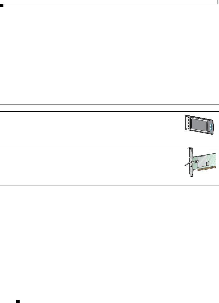
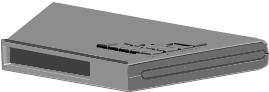
Table 1-1 |
Client Adapter Types |
Client Adapter |
Model Number |
Description |
Illustration |
PC-Cardbus |
AIR-CB21AG |
An IEEE 802.11a/b/g-compliant 2.4- and 5-GHz 54-Mbps client |
|
card |
|
adapter card radio module with a Cardbus interface that can be |
|
|
|
inserted into any device equipped with a 32-bit Cardbus slot. Host |
|
|
|
devices can include laptops and notebook computers. |
|
PCI card |
AIR-PI21AG |
An IEEE 802.11a/b/g-compliant 2.4- and 5-GHz 54-Mbps client |
|
|
|
adapter card radio module that can be inserted into any device |
|
|
|
equipped with an empty PCI expansion slot, such as a desktop |
|
|
|
personal computer. |
|
|
|
|
STATUS ACTIVITY |
95579
Terminology
The following terms are used throughout this document:
•client adapter—Refers to both types of adapters.
•PC-Cardbus card or PCI card—Refers to a specific adapter.
•workstation (or station)—Refers to a computing device with an installed client adapter.
•infrastructure device—Refers to a device that connects client adapters to a wired LAN, such as an access point, bridge, or base station. Throughout this document, access point is used to represent infrastructure devices in general.
Cisco Aironet 802.11a/b/g Wireless LAN Client Adapters (CB21AG and PI21AG) Installation and Configuration Guide for Windows Vista
1-2 |
OL-16534-01 |
|
|

Chapter 1 Product Overview and Installation
Hardware Components
Hardware Components
The client adapters have three major hardware components: a radio, a radio antenna, and two LEDs.
Radio
The client adapters contain a dual-band radio that is both IEEE 802.11a and 802.11b/g compliant. The radio uses both direct-sequence spread spectrum (DSSS) technology and orthogonal frequency division multiplexing (OFDM) technology for client applications in the 2.4-GHz Industrial Scientific Medical (ISM) frequency band and OFDM technology in the 5-GHz Unlicensed National Information Infrastructure (UNII) frequency bands. The client adapters operate with other IEEE 802.11a or 802.11b/g-compliant client devices in ad hoc mode or with Cisco Aironet access points and other IEEE 802.11a or 802.11b/g-compliant infrastructure devices in infrastructure mode.
Radio Antenna
The type of antenna used depends on your client adapter:
•PC-Cardbus cards have an integrated, permanently attached 0-dBi gain, dual-band 2.4/5-GHz diversity antenna. The benefit of the diversity antenna system is improved coverage. The system works by enabling the card to sample and switch between its two antenna ports in order to select the optimum port for receiving data packets. As a result, the card has a better chance of maintaining the radio frequency (RF) connection in areas of interference. The antenna is housed within the section of the card that hangs out of the Cardbus slot when the card is installed.
•PCI cardshave a 1-dBi gain, dual-band 2.4/5-GHz antenna that is permanently attached by a 6.6-foot (2-meter) cable. A base is provided with the antenna to enable it to be mounted to a wall or to sit upright on a desk or other horizontal surface.
LEDs
The client adapters have two LEDs that glow or blink to indicate the status of the adapter or to convey system messages. Table 1-2 provides interpreations of the the LEDs.
Table 1-2 |
LED Operating Messages |
|
|
|
|
|
|
Status LED (green) |
Activity LED (amber) |
Condition |
|
|
|
|
|
Off |
|
Off |
Client adapter is not receiving power. |
|
|
|
|
Blinking slowly |
Off |
Client adapter is in power save mode. |
|
|
|
|
|
On |
|
Off |
Client adapter has awakened from power save mode. |
|
|
|
|
Alternating blink: |
|
Client adapter is scanning for the wireless network |
|
|
|
|
for which it is configured. |
On |
|
Off |
|
|
|
||
|
|
|
|
Off |
|
On |
|
|
|
|
|
Cisco Aironet 802.11a/b/g Wireless LAN Client Adapters (CB21AG and PI21AG) Installation and Configuration Guide for Windows Vista
|
OL-16534-01 |
1-3 |
|
|
|

Chapter 1 Product Overview and Installation
Software Components
Table 1-2 |
LED Operating Messages (continued) |
||
|
|
|
|
Status LED (green) |
Activity LED (amber) |
Condition |
|
|
|
|
|
Blinking slowly |
Blinking slowly |
Client adapter is associated to an access point (in |
|
|
|
|
infrastructure mode) or another client (in ad hoc |
|
|
|
mode). |
|
|
|
|
Blinking quickly |
Blinking quickly |
Client adapter is transmitting or receiving data |
|
|
|
|
while associated to an access point (in infrastructure |
|
|
|
mode) or another client (in ad hoc mode). |
|
|
|
|
Software Components
You can install both the driver for the CB21AG and PI21AG and the software that runs the adapter by running a single executable file that is available from Cisco.com. You must execute this file on devices that are running Windows Vista. This driver and softward can be used only with CB21AG and PI21AG client adapters.
Network Configurations Using Client Adapters
Client adapters can be used in a variety of network configurations. In some configurations, access points provide connections to your network or act as repeaters to increase wireless communication range. The maximum communication range is based on how you configure your wireless network.
This section describes and illustrates the two most common network configurations:
•Ad hoc wireless local area network (LAN)
•Wireless infrastructure with workstations accessing a wired LAN
For examples of more complex network configurations involving client adapters and access points, refer to the documentation for your access point.
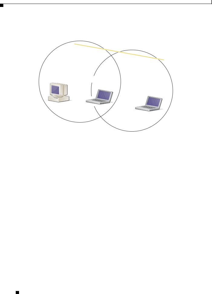
Ad Hoc Wireless LAN
An ad hoc (or peer-to-peer) wireless LAN (see Figure 1-1) is the simplest wireless LAN configuration. In a wireless LAN using an ad hoc network configuration, all devices equipped with a client adapter can be linked together and communicate directly with each other. The use of an infrastructure device, such as an access point, is not required.
Cisco Aironet 802.11a/b/g Wireless LAN Client Adapters (CB21AG and PI21AG) Installation and Configuration Guide for Windows Vista
1-4 |
OL-16534-01 |
|
|

Chapter 1 Product Overview and Installation
Network Configurations Using Client Adapters
Figure 1-1 Ad Hoc Wireless LAN
47520
Wireless Infrastructure with Workstations Accessing a Wired LAN
A infrastructure network can be created by placing two or more access points on a LAN. Figure 1-2 shows a microcellular network with workstations accessing a wired LAN through several access points.
This configuration is useful with portable or mobile stations because it enables them to be directly connected to the wired network even while moving from one microcell domain to another. This process is transparent, and the connection to the file server or host is maintained without disruption. The mobile station stays connected to an access point as long as it can. However, when the transfer of data packets needs to be retried or beacons are missed, the station automatically searches for and associates to another access point. This process is referred to as seamless roaming.
Cisco Aironet 802.11a/b/g Wireless LAN Client Adapters (CB21AG and PI21AG) Installation and Configuration Guide for Windows Vista
|
OL-16534-01 |
1-5 |
|
|
|
Chapter 1 Product Overview and Installation
Safety information
Figure 1-2 Wireless Infrastructure with Workstations Accessing a Wired LAN
Access Point
(Root Unit)
Wired LAN |
Access Point |
|
(Root Unit) |
65999
Safety information
Follow the guidelines in this section to ensure proper operation and safe use of the client adapter.
FCC Safety Compliance Statement
The FCC, with its action in ET Docket 96-8, has adopted a safety standard for human exposure to RF electromagnetic energy emitted by FCC-certified equipment. When used with approved Cisco Aironet antennas, Cisco Aironet products meet the uncontrolled environmental limits found in OET-65 and ANSI C95.1, 1991. Proper operation of this radio device according to the instructions in this publication will result in user exposure substantially below the FCC recommended limits.
Safety Guidelines
•Do not touch or move the antenna while the unit is transmitting or receiving.
•Do not hold any component containing a radio such that the antenna is very close to or touching any exposed parts of the body, especially the face or eyes, while transmitting.
•Do not operate the radio or attempt to transmit data unless the antenna is connected; otherwise, the radio may be damaged.
Cisco Aironet 802.11a/b/g Wireless LAN Client Adapters (CB21AG and PI21AG) Installation and Configuration Guide for Windows Vista
1-6 |
OL-16534-01 |
|
|

Chapter 1 Product Overview and Installation
Unpacking the Client Adapter
•Use in specific environments:
–The use of wireless devices in hazardous locations is limited to the constraints posed by the safety directors of such environments.
–The use of wireless devices on airplanes is governed by the Federal Aviation Administration (FAA).
–The use of wireless devices in hospitals is restricted to the limits set forth by each hospital.
Warnings
Observe the following warnings when operating the client adapter. The second warning pertains to the PI21AG client adapter, and the third warning pertains to the CB21AG client adapter.
Warning Do not operate your wireless network device near unshielded blasting caps or in an explosive environment unless the device has been modified to be especially qualified for such use.
Warning In order to comply with FCC radio frequency (RF) exposure limits, antennas should be located at a minimum of 7.9 inches (20 cm) or more from the body of all persons.
Warning This device has been tested and complies with FCC RF Exposure (SAR) limits in typical laptop computer configurations and this device can be used in desktop or laptop computers with side mounted PC Card slots that can provide at least 0.394 in (1 cm) separation distance from the antenna to the body of the user or a nearby person. Thin laptop computers may need special attention to maintain antenna spacing while operating. This device cannot be used with handheld PDAs (personal digital assistants). Use in other configurations may not ensure compliance with FCC RF exposure guidelines. This device and its antenna must not be co-located or operated in conjunction with any other antenna or transmitter.
Translated versions of these safety warnings are provided in Appendix B
Unpacking the Client Adapter
Follow these steps to unpack the client adapter:
Step 1 Open the shipping container and carefully remove the contents.
Step 2 Return all packing materials to the shipping container and save the container.
Step 3 Ensure that all items listed in the “Package Contents” section below are included in the shipment. Check each item for damage.
Note If any item is damaged or missing, notify your authorized Cisco sales representative.
Cisco Aironet 802.11a/b/g Wireless LAN Client Adapters (CB21AG and PI21AG) Installation and Configuration Guide for Windows Vista
|
OL-16534-01 |
1-7 |
|
|
|
Chapter 1 Product Overview and Installation
System Requirements
Package Contents
Each client adapter is shipped with the following items:
•1-dBi gain antenna permanently attached by a 6.6-ft (2-m) cable, antenna base, low-profile bracket, two mounting screws, and two plastic wall anchors (PCI cards only)
•Quick Start Guide: Cisco Aironet 802.11a/b/g Wireless LAN Client Adapters (CB21AG and PI21AG)
•Cisco Aironet 802.11a/b/g Wireless Adapters (CB21AG and PI21AG) CD
System Requirements
In addition to the items shipped with the client adapter, you also need the following items in order to install and use the adapter:
•One of the following computing devices running Windows Vista.
–Laptop or notebook computer equipped with a 32-bit Cardbus slot
–Desktop personal computer equipped with an empty PCI expansion slot
•Windows Vista Service Pack 1 or Windows Vista with hotfix KB932063 and hotfix KB935222
Note You must obtain these hotfix patches from the Microsoft site. You must also contact Microsoft directly for any support that you need for these patches.
http://support.microsoft.com/kb/932063
http://support.microsoft.com/kb/935222
Note The client adapter software supports Windows Vista Business, Enterprise, and Ultimate operating systems.
•1 GHz 32-bit (x86) or 64-bit (x64) processor.
•1 GB of system memory
•40 GB hard drive with at least 15 GB of available space
•The appropriate tools for removing your computer’s cover and expansion slot dust cover and for mounting the antenna base (for PCI cards)
•If your wireless network uses EAP-TLS or PEAP authentication, Certificate Authority (CA) and user certificates for EAP-TLS authentication or CA certificate for PEAP authentication
•If your wireless network uses PEAP (EAP-GTC) authentication with a One-Time Password (OTP) user database:
–A hardware token device from OTP vendors or the Secure Computing SofToken program (version 2.1 or later)
–Your hardware or software token password
•All necessary infrastructure devices (such as access points, servers, gateways, user databases, etc.) must be properly configured for any authentication type you plan to enable on the client.
•The following information from your system administrator:
Cisco Aironet 802.11a/b/g Wireless LAN Client Adapters (CB21AG and PI21AG) Installation and Configuration Guide for Windows Vista
1-8 |
OL-16534-01 |
|
|
Chapter 1 Product Overview and Installation
Site Requirements
–The logical name for your workstation (also referred to as client name)
–The protocols necessary to bind to the client adapter, such as TCP/IP
–The case-sensitive service set identifier (SSID) for your RF network
–If your network setup does not include a DHCP server, the IP address, subnet mask, and default gateway address of your computer
–The wired equivalent privacy (WEP) keys of the access points with which your client adapter will communicate, if your wireless network uses static WEP for security
–The username and password for your network account
–Protected access credentials (PAC) file if your wireless network uses EAP-FAST authentication with manual PAC provisioning
Site Requirements
This section discusses the site requirements for both infrastructure and client devices.
For Infrastructure Devices
Because of differences in component configuration, placement, and physical environment, every network application is a unique installation. Therefore, before you install any wireless infrastructure devices (such as access points, bridges, and base stations, which connect your client adapters to a wired LAN), a site survey must be performed to determine the optimum placement of these devices to maximize range, coverage, and network performance.
Note Infrastructure devices are installed and initially configured prior to client devices.
For Client Devices
Because the client adapter is a radio device, it is susceptible to RF obstructions and common sources of interference that can reduce throughput and range. Follow these guidelines to ensure the best possible performance:
•Install the client adapter in an area where large steel structures such as shelving units, bookcases, and filing cabinets will not obstruct radio signals to and from the client adapter.
•Install the client adapter away from microwave ovens. Microwave ovens operate on the same frequency as the client adapter and can cause signal interference.
Cisco Aironet 802.11a/b/g Wireless LAN Client Adapters (CB21AG and PI21AG) Installation and Configuration Guide for Windows Vista
|
OL-16534-01 |
1-9 |
|
|
|
Chapter 1 Product Overview and Installation
Inserting the Client Adapter
Inserting the Client Adapter
This section provides instructions for inserting a PC-Cardbus card or PCI card into your computer.
Caution These procedures and the physical connections they describe apply generally to conventional Cardbus slots and PCI expansion slots. In cases of custom or nonconventional equipment, be alert to possible differences in Cardbus slot and PCI expansion slot configurations.
Inserting a PC-Cardbus Card
Step 1 Before you begin, examine the card. One end has a dual-row, 68-pin connector. The card is keyed so it can be inserted only one way into the Cardbus slot.
Note The PC-Cardbus slot, if supported, is usually on the left or right side of a laptop computer, depending on the model.
Step 2 Turn on your computer and let the operating system boot up completely.
Step 3 Hold the card with the Cisco label facing up and insert it into the Cardbus slot, applying just enough pressure to make sure it is fully seated (see Figure 1-3). The green LED lights when the card is inserted properly.
Caution Do not force the card into your computer’s Cardbus slot. Forcing it will damage both the card and the slot. If the card does not insert easily, remove the card and reinsert it.
Figure 1-3 Inserting a PC-Cardbus Card into a Computer
 32617
32617
Note The configuration profiles for PC-Cardbus cards are tied to the slot in which the card is inserted. Therefore, you must always insert your PC-Cardbus card into the same slot or create profiles for both slots. See Chapter 4 for information on creating profiles for your client adapter.
|
Cisco Aironet 802.11a/b/g Wireless LAN Client Adapters (CB21AG and PI21AG) Installation and Configuration Guide for Windows Vista |
1-10 |
OL-16534-01 |
Chapter 1 Product Overview and Installation
Inserting the Client Adapter
Step 4 If the Found New Hardware Wizard window appears, click Cancel.
Note If you do not click Cancel, the wizard will attempt to install software for the client adapter but will be unable to find it.
Step 5 Go to the “Installing the Client Adapter Driver and Software” section on page 1-18.
Inserting a PCI Card
You must perform the following procedures in the order listed below to insert a PCI card:
•If required, change the bracket (see the “Changing the Bracket” section on page 1-11).
•Insert the card (see the “Inserting the Card” section on page 1-12).
•Assemble the antenna (see the “Assembling the Antenna” section on page 1-13).
•Mount the antenna (see the “Mounting the Antenna” section on page 1-14).
Changing the Bracket
The PCI card is shipped with a full-profile bracket attached. If the PC into which you are inserting the PCI card requires the card to use a low-profile bracket, follow these steps to change brackets.
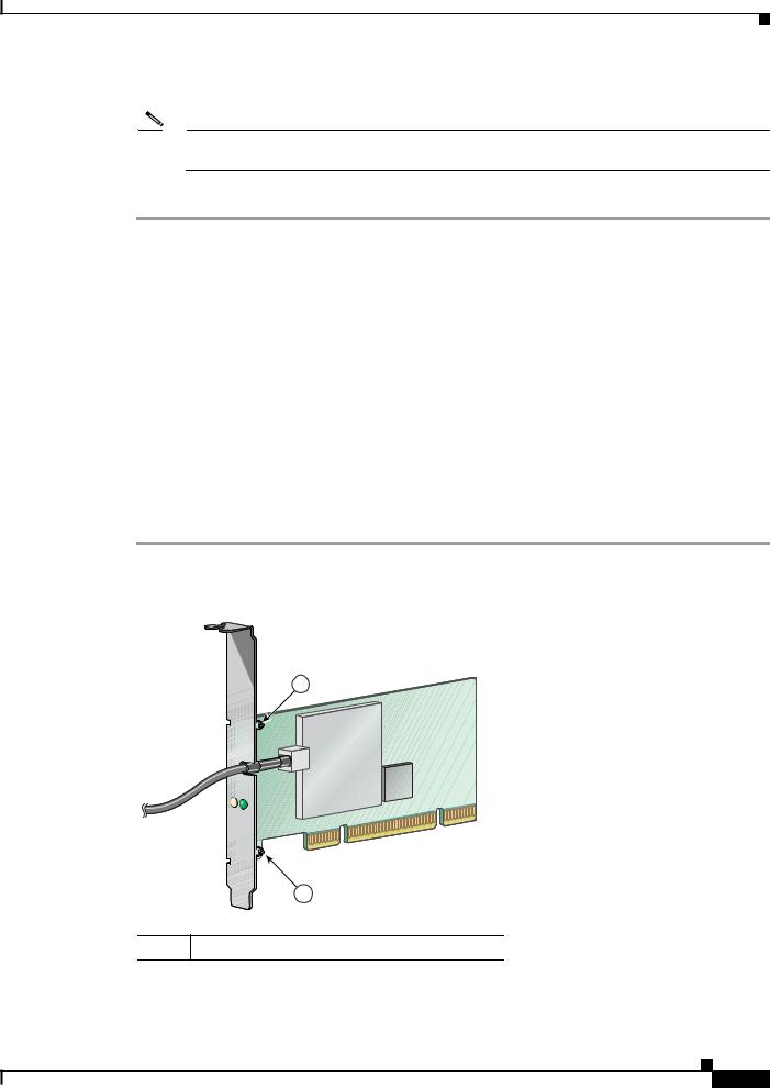
Step 1 Remove the two screws that attach the bracket to the card. See Figure 1-4.
Figure 1-4 Changing the PCI Card Bracket
1
ACTIVITY |
STATUS |
1
95581
1 Bracket screws
Cisco Aironet 802.11a/b/g Wireless LAN Client Adapters (CB21AG and PI21AG) Installation and Configuration Guide for Windows Vista
OL-16534-01 1-11
Chapter 1 Product Overview and Installation
Inserting the Client Adapter
Step 2 Slide the bracket away from the card; then tilt the bracket to free the antenna cable.
Caution Do not pull on the antenna cable or detach it from the PCI card. The antenna is meant to be permanently attached to the card.
Step 3 Hold the low-profile bracket to the card so that the LEDs slip through their corresponding holes on the bracket.
Step 4 Insert the screws that you removed in Step 1into the holes on the populated side of the card near the bracket (see Figure 1-4) and tighten.
Inserting the Card
Follow the steps below to insert a PCI card into your PC.
Step 1 Turn off the PC and all its components.
Step 2 Remove the computer cover.
Note On most Pentium PCs, PCI expansion slots are white. Refer to your PC documentation for slot identification.
Step 3 Remove the screw from the top of the CPU back panel above an empty PCI expansion slot. This screw holds the metal bracket on the back panel.
Caution Static electricity can damage your PCI card. Before removing the card from the anti-static packaging, discharge static by touching a metal part of a grounded PC.
Step 4 Locate an empty PCI expansion slot inside your computer.
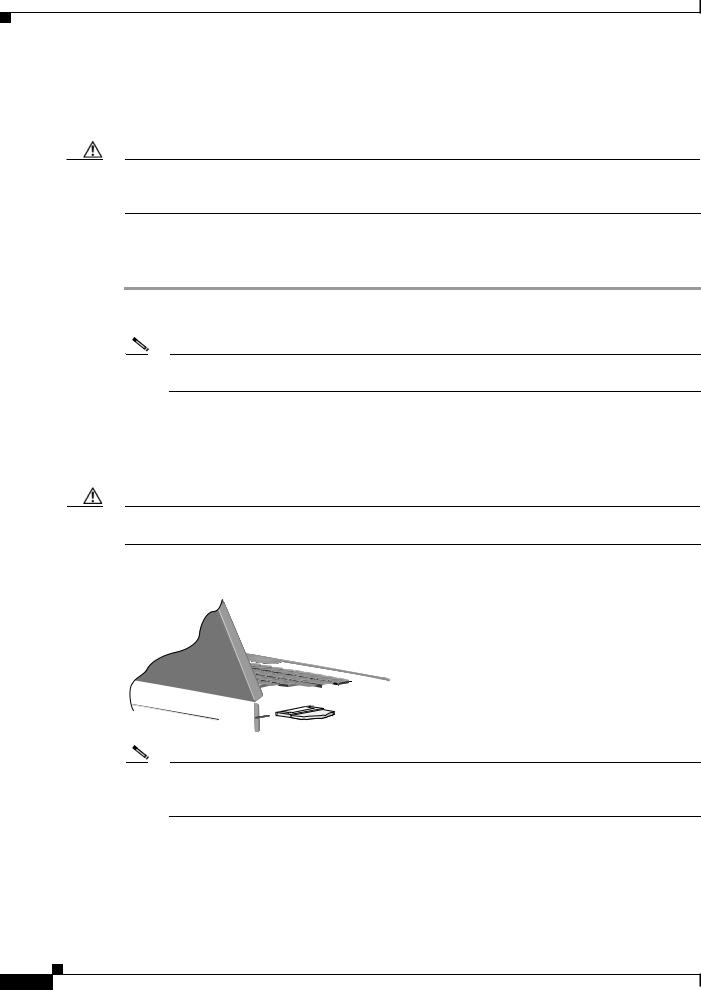
Step 5 Slip your card’s antenna through the opening near the empty expansion slot so that it is located outside of the computer. See Figure 1-5.
|
Cisco Aironet 802.11a/b/g Wireless LAN Client Adapters (CB21AG and PI21AG) Installation and Configuration Guide for Windows Vista |
1-12 |
OL-16534-01 |

Chapter 1 Product Overview and Installation
Inserting the Client Adapter
Figure 1-5 Inserting a PCI Card into a PC
2 |
ACTIVITY |
STATUS |
|
1 


 3
3
95582
1Antenna cable
2LEDs
3Card edge connector
Step 6 Tilt the card to enable the LEDs to slip through the opening in the CPU back panel. See the enlarged view in Figure 1-5.
Step 7 Press the card into the empty slot until its connector is firmly seated.
Caution Do not force the card into the expansion slot; this could damage both the card and the slot. If the card does not insert easily, remove it and reinsert it.
Step 8 Reinstall the screw on the CPU back panel and replace the computer cover.
Assembling the Antenna
Follow the steps below to assemble the PCI card’s antenna.
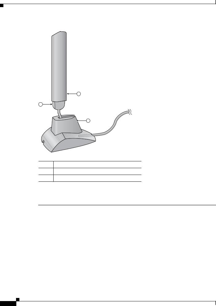
Step 1 Slide the antenna through the opening in the bottom of the antenna base.
Step 2 Position the antenna so its notches are facing the Cisco label on the front of the base. See Figure 1-6.
Cisco Aironet 802.11a/b/g Wireless LAN Client Adapters (CB21AG and PI21AG) Installation and Configuration Guide for Windows Vista
OL-16534-01 1-13
Chapter 1 Product Overview and Installation
Inserting the Client Adapter
Figure 1-6 Inserting the Antenna into Its Base
1
2
3
95584
1Antenna
2Notch
3Antenna base
Step 3 Press the antenna cable into the receptacle on the top of the base as shown in Figure 1-6.
Step 4 Press the antenna straight down into the receptacle until it clicks into place.
Mounting the Antenna
Because the PCI card is a radio device, it is susceptible to RF obstructions and common sources of interference that can reduce throughput and range. Follow these guidelines to ensure the best possible performance:
•Place the PCI card’s antenna in an area where large steel structures such as shelving units, bookcases, and filing cabinets will not obstruct radio signals being transmitted or received.
•Place the antenna away from microwave ovens and 2.4- and 5.8-GHz cordless phones. These products can cause signal interference because they operate in the same frequency range as the PCI card.
|
Cisco Aironet 802.11a/b/g Wireless LAN Client Adapters (CB21AG and PI21AG) Installation and Configuration Guide for Windows Vista |
1-14 |
OL-16534-01 |
Chapter 1 Product Overview and Installation
Inserting the Client Adapter
Follow the steps below to position the PCI card’s antenna on a flat horizontal surface or to mount it to a wall.
Step 1 Perform one of the following:
•If you want to use the antenna on a flat horizontal surface, position the antenna so it is pointing straight up. Then go to Step 7.
•If you want to mount the antenna to a wall, go to Step 2.
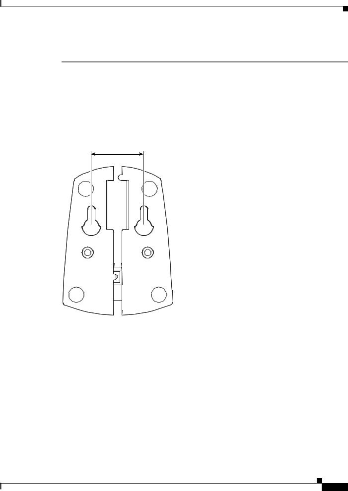
Step 2 Drill two holes in the wall that are 1.09 in. (2.8 cm) apart. Figure 1-7 shows the distance between the mounting holes on the bottom of the antenna base.
Figure 1-7 Bottom of Antenna Base
1.09 inches
95597
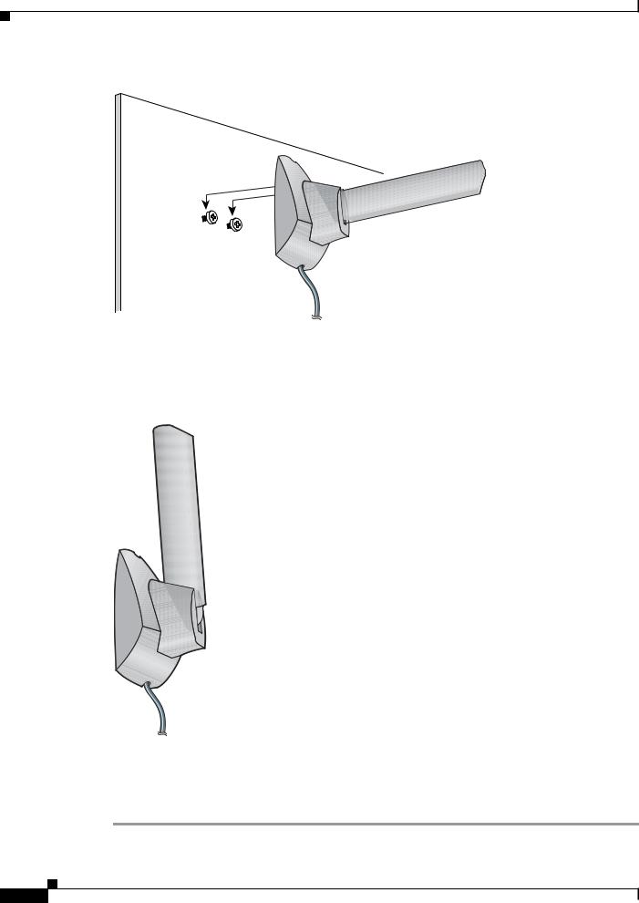
Step 3 Tap the two supplied wall anchors into the holes.
Step 4 Drive the two supplied screws into the wall anchors, leaving a small gap between the screw head and the anchor.
Step 5 Position the mounting holes on the bottom of the antenna base over the screws (see Figure 1-8) and pull down to lock in place.
Cisco Aironet 802.11a/b/g Wireless LAN Client Adapters (CB21AG and PI21AG) Installation and Configuration Guide for Windows Vista
OL-16534-01 1-15
Chapter 1 Product Overview and Installation
Inserting the Client Adapter
Figure 1-8 Mounting the Antenna
95595
Step 6 The antenna rotates 90 degrees from its base. For optimal reception, position the antenna so it is pointing straight up (see Figure 1-9).
Figure 1-9 Rotating the Antenna
95596
Step 7 Boot up your PC.The green LED lights when the card is inserted properly.
Step 8 If the Found New Hardware Wizard window appears, click Cancel.
Step 9 Go to the “Installing the Client Adapter Driver and Software” section on page 1-18.
|
Cisco Aironet 802.11a/b/g Wireless LAN Client Adapters (CB21AG and PI21AG) Installation and Configuration Guide for Windows Vista |
1-16 |
OL-16534-01 |

Chapter 1 Product Overview and Installation
Obtaining Client Adapter Software
Obtaining Client Adapter Software
The software is provided on the CD that shipped with your client adapter; however, Cisco recommends retrieving it from Cisco.com to ensure that you have the latest version.
•To obtain the version of the software on the CD, open the FileList.txt file on the CD root directory.
•To obtain the version of the latest software on Cisco.com, follow these steps:
Step 1 Make sure that you have a Cisco.com username and password.
Step 2 If you do not have a Cisco.com username and password, go to Cisco’s main page (http://www.cisco.com) and click Register (top). Follow the instructions to create a username and password.
Step 3 Use your computer’s web browser to access the following URL:
Step 4 http://www.cisco.com/public/sw-center/
Step 5 Click Wireless Software.
Step 6 Click Client Adapters and Client Software.
Step 7 Click Cisco Aironet Wireless LAN Client Adapters.
Step 8 Follow one of these steps:
Step 9 If you are using a PC-Cardbus card, click Cisco Aironet 802.11a/b/g CardBus Wireless LAN Client Adapter (CB21AG).
Step 10 If you are using a PCI card, click Cisco Aironet 802.11a/b/g PCI Wireless LAN Client Adapter (PI21AG).
Step 11 When prompted, enter your Cisco.com username and password, and click OK.
Step 12 Click Windows Vista.
Step 13 Under Available Releases, determine whether the Install Wizard file on Cisco.com has a later version number than the file on the CD. If it does, proceed to the next step. If it does not, use the Install Wizard file on your CD.
Step 14 Click the link with the latest release number.
Step 15 Click the software file (WinClient-802.11a-b-g-Vista-Ins-Wizard-vxx.exe), where xx is the version number.
Step 16 Click the Download button.
Step 17 Read and accept the terms and conditions of the Software License Agreement. Click Agree to accept the terms and condition, or click Decline not to accept. Save the file to your device.
Cisco Aironet 802.11a/b/g Wireless LAN Client Adapters (CB21AG and PI21AG) Installation and Configuration Guide for Windows Vista
OL-16534-01 1-17
Chapter 1 Product Overview and Installation
Installing the Client Adapter Driver and Software
Installing the Client Adapter Driver and Software
Caution Do not eject your client adapter at any time during the installation process, including during the reboot.
Follow these steps to use to install the client software on a device that is running Windows Vista.
Step 1 Double-click WinClient-802.11a-b-g-Vista-Ins-Wizard-vxx.exe. A window appears that asks you if you want to run the softward file.
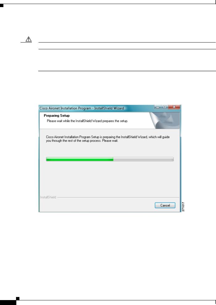
Step 2 Click Run. The Cisco Aironet Installation Program - InstallShield window appears (see Figure 1-10).
Figure 1-10 Cisco Aironet Installation Program—Installation Wizard Preparing Setup Window
Step 3 Allow the preparation sequence to finish . After the preparation sequence finishes, the next Cisco Aironet Installation Program window appears (see Figure 1-11).
|
Cisco Aironet 802.11a/b/g Wireless LAN Client Adapters (CB21AG and PI21AG) Installation and Configuration Guide for Windows Vista |
1-18 |
OL-16534-01 |
Loading...