


 Loading...
Se n d d o c u m e n t c o m m e n t s t o n ex u s 3 k - d o c f e e d b a ck @ c i s c o . c o m
Cisco Nexus 3000 Series Hardware
Installation Guide
December, 2013
Americas Headquarters
Cisco Systems, Inc. 170 West Tasman Drive
San Jose, CA 95134-1706 USA http://www.cisco.com Tel: 408 526-4000
800 553-NETS (6387) Fax: 408 527-0883
Text Part Number: OL-25338-04
Se n d d o c u m e n t c o m m e n t s t o n ex u s 3 k - d o c f e e d b a ck @ c i s c o . c o m
THE SPECIFICATIONS AND INFORMATION REGARDING THE PRODUCTS IN THIS MANUAL ARE SUBJECT TO CHANGE WITHOUT NOTICE. ALL STATEMENTS, INFORMATION, AND RECOMMENDATIONS IN THIS MANUAL ARE BELIEVED TO BE ACCURATE BUT ARE PRESENTED WITHOUT WARRANTY OF ANY KIND, EXPRESS OR IMPLIED. USERS MUST TAKE FULL RESPONSIBILITY FOR THEIR APPLICATION OF ANY PRODUCTS.
THE SOFTWARE LICENSE AND LIMITED WARRANTY FOR THE ACCOMPANYING PRODUCT ARE SET FORTH IN THE INFORMATION PACKET THAT SHIPPED WITH THE PRODUCT AND ARE INCORPORATED HEREIN BY THIS REFERENCE. IF YOU ARE UNABLE TO LOCATE THE SOFTWARE LICENSE OR LIMITED WARRANTY, CONTACT YOUR CISCO REPRESENTATIVE FOR A COPY.
The following information is for FCC compliance of Class A devices: This equipment has been tested and found to comply with the limits for a Class A digital device, pursuant to part 15 of the FCC rules. These limits are designed to provide reasonable protection against harmful interference when the equipment is operated in a commercial environment. This equipment generates, uses, and can radiate radio-frequency energy and, if not installed and used in accordance with the instruction manual, may cause harmful interference to radio communications. Operation of this equipment in a residential area is likely to cause harmful interference, in which case users will be required to correct the interference at their own expense.
The following information is for FCC compliance of Class B devices: This equipment has been tested and found to comply with the limits for a Class B digital device, pursuant to part 15 of the FCC rules. These limits are designed to provide reasonable protection against harmful interference in a residential installation. This equipment generates, uses and can radiate radio frequency energy and, if not installed and used in accordance with the instructions, may cause harmful interference to radio communications.
However, there is no guarantee that interference will not occur in a particular installation. If the equipment causes interference to radio or television reception, which can be determined by turning the equipment off and on, users are encouraged to try to correct the interference by using one or more of the following measures:
•Reorient or relocate the receiving antenna.
•Increase the separation between the equipment and receiver.
•Connect the equipment into an outlet on a circuit different from that to which the receiver is connected.
•Consult the dealer or an experienced radio/TV technician for help.
Modifications to this product not authorized by Cisco could void the FCC approval and negate your authority to operate the product.
The Cisco implementation of TCP header compression is an adaptation of a program developed by the University of California, Berkeley (UCB) as part of UCB’s public domain version of the UNIX operating system. All rights reserved. Copyright © 1981, Regents of the University of California.
NOTWITHSTANDING ANY OTHER WARRANTY HEREIN, ALL DOCUMENT FILES AND SOFTWARE OF THESE SUPPLIERS ARE PROVIDED “AS IS” WITH ALL FAULTS. CISCO AND THE ABOVE-NAMED SUPPLIERS DISCLAIM ALL WARRANTIES, EXPRESSED OR IMPLIED, INCLUDING, WITHOUT LIMITATION, THOSE OF MERCHANTABILITY, FITNESS FOR A PARTICULAR PURPOSE AND NONINFRINGEMENT OR ARISING FROM A COURSE OF DEALING, USAGE, OR TRADE PRACTICE.
IN NO EVENT SHALL CISCO OR ITS SUPPLIERS BE LIABLE FOR ANY INDIRECT, SPECIAL, CONSEQUENTIAL, OR INCIDENTAL DAMAGES, INCLUDING, WITHOUT LIMITATION, LOST PROFITS OR LOSS OR DAMAGE TO DATA ARISING OUT OF THE USE OR INABILITY TO USE THIS MANUAL, EVEN IF CISCO OR ITS SUPPLIERS HAVE BEEN ADVISED OF THE POSSIBILITY OF SUCH DAMAGES.
Cisco and the Cisco logo are trademarks or registered trademarks of Cisco and/or its affiliates in the U.S. and other countries. To view a list of Cisco trademarks, go to this URL: www.cisco.com/go/trademarks. Third-party trademarks mentioned are the property of their respective owners. The use of the word partner does not imply a partnership relationship between Cisco and any other company. (1110R)
Any Internet Protocol (IP) addresses and phone numbers used in this document are not intended to be actual addresses and phone numbers. Any examples, command display output, network topology diagrams, and other figures included in the document are shown for illustrative purposes only. Any use of actual IP addresses or phone numbers in illustrative content is unintentional and coincidental.
Cisco Nexus 3000 Series Hardware Installation Guide
© 2013 Cisco Systems, Inc. All rights reserved.

Se n d d o c u m e n t c o m m e n t s t o n ex u s 3 k - d o c f e e d b a ck @ c i s c o . c o m
|
|
|
|
|
|
|
C O N T E N T S |
|||||
|
|
Preface vii |
|
|
|
|
|
|
|
|
|
|
|
|
Audience vii |
|
|
|
|
|
|
|
|
|
|
|
|
Organization |
vii |
|
|
|
|
|
|
|
|
|
|
|
Conventions |
viii |
|
|
|
|
|
|
|
|
|
|
|
Related Documentation xiii |
|
|
|
|
|
|
|
|||
|
|
Release Notes |
xiv |
|
|
|
|
|
|
|
|
|
|
|
Configuration Guides |
xiv |
|
|
|
|
|
|
|
||
|
|
Installation and Upgrade Guides xiv |
|
|
|
|
|
|
|
|||
|
|
Licensing Guide |
xiv |
|
|
|
|
|
|
|
|
|
|
|
Command References |
xiv |
|
|
|
|
|
|
|
||
|
|
Technical References |
xiv |
|
|
|
|
|
|
|
||
|
|
Error and System Messages xiv |
|
|
|
|
|
|
|
|||
|
|
Obtaining Documentation and Submitting a Service Request xv |
||||||||||
|
Overview of the Cisco Nexus 3000 Series Switches |
|
|
|
|
|||||||
C H A P T E R 1 |
1-1 |
|
|
|
||||||||
|
|
Cisco Nexus 3016 Switch |
1-1 |
|
|
|
|
|
|
|
||
|
|
Chassis for the Cisco Nexus 3016 Switch |
|
1-2 |
|
|
|
|
|
|||
|
|
Ports for the Cisco Nexus 3016 Switch |
1-3 |
|
|
|
|
|
||||
|
|
Power Supply for the Cisco Nexus 3016 Switch |
1-4 |
|
|
|
|
|||||
|
|
Fan Tray for the Cisco Nexus 3016 Switch |
1-5 |
|
|
|
|
|
||||
|
|
Port Connections for the Cisco Nexus 3016 Switch |
1-5 |
|
|
|
||||||
|
|
Cisco Nexus 3048 Switch |
1-6 |
|
|
|
|
|
|
|
||
|
|
Chassis for the Cisco Nexus 3048 Switch |
|
1-6 |
|
|
|
|
|
|||
|
|
Ports for the Cisco Nexus 3048 Switch |
1-8 |
|
|
|
|
|
||||
|
|
Power Supply for the Cisco Nexus 3048 Switch |
1-9 |
|
|
|
|
|||||
|
|
Fan Tray for the Cisco Nexus 3048 Switch |
1-10 |
|
|
|
|
|
||||
|
|
Port Connections for the Cisco Nexus 3048 Switch |
1-10 |
|
|
|
||||||
|
|
Cisco Nexus 3064 Switch |
1-11 |
|
|
|
|
|
|
|
||
|
|
Chassis for the Cisco Nexus 3064 Switch |
|
1-12 |
|
|
|
|
|
|||
|
|
Ports for the Cisco Nexus 3064 Switch |
1-13 |
|
|
|
|
|
||||
|
|
Power Supply for the Cisco Nexus 3064 Switch |
1-14 |
|
|
|
||||||
|
|
Fan Tray for the Cisco Nexus 3064 Switch |
1-14 |
|
|
|
|
|
||||
|
|
Port Connections for the Cisco Nexus 3064 Switch |
1-15 |
|
|
|
||||||
|
|
Cisco Nexus 3132Q Switch |
1-16 |
|
|
|
|
|
|
|
||
|
|
|
|
|
|
Cisco Nexus 3000 Series Hardware Installation Guide |
|
|
|
|||
|
|
|
|
|
|
|
||||||
|
|
|
|
|
|
|
|
|
|
|
|
|
|
OL-25338-04 |
|
|
|
|
|
|
|
|
|
iii |
|
|
|
|
|
|
|
|
|
|
|
|
||

Contents
Se n d d o c u m e n t c o m m e n t s t o n ex u s 3 k - d o c f e e d b a ck @ c i s c o . c o m
|
|
|
|
|
Chassis for the Cisco Nexus 3132Q Switch |
1-17 |
|
|
|
||||||
|
|
|
|
|
Ports for the Cisco Nexus 3132Q Switch |
|
1-18 |
|
|
|
|||||
|
|
|
|
|
Power Supply for the Cisco Nexus 3132Q Switch |
1-18 |
|
|
|||||||
|
|
|
|
|
Fan Tray for the Cisco Nexus 3132Q Switch |
1-19 |
|
|
|
||||||
|
|
|
|
|
Transceiver and Cabling Options for the Cisco Nexus 3132Q Switch |
1-20 |
|
||||||||
|
|
|
|
|
Cisco Nexus 3172PQ Switch 1-21 |
|
|
|
|
|
|
|
|||
|
|
|
|
|
Chassis for the Cisco Nexus 3172PQ Switch |
1-21 |
|
|
|
||||||
|
|
|
|
|
Ports for the Cisco Nexus 3172PQ Switch |
1-23 |
|
|
|
||||||
|
|
|
|
|
Power Supply for the Cisco Nexus 3172PQ Switch |
1-23 |
|
|
|||||||
|
|
|
|
|
Fan Tray for the Cisco Nexus 3172PQ Switch |
1-24 |
|
|
|||||||
|
|
|
|
|
Transceiver and Cabling Options for the Cisco Nexus 3172PQ Switch |
1-24 |
|
||||||||
|
|
|
|
|
Cisco Nexus 3548 and Cisco Nexus 3524 Switches |
1-26 |
|
|
|||||||
|
|
|
|
|
Chassis for the Cisco Nexus 3548 Switch |
1-27 |
|
|
|
||||||
|
|
|
|
|
Ports for the Cisco Nexus 3548 Switch |
1-28 |
|
|
|
|
|||||
|
|
|
|
|
Power Supply for the Cisco Nexus 3548 Switch 1-29 |
|
|
||||||||
|
|
|
|
|
Fan Tray for the Cisco Nexus 3548 Switch |
1-29 |
|
|
|
||||||
|
|
|
|
|
Port Connections for the Cisco Nexus 3548 Switch |
1-30 |
|
|
|||||||
|
|
|
Installing the Cisco Nexus 3000 Series Switches |
|
|
|
|
||||||||
C H A P T E R |
2 |
|
2-1 |
|
|
|
|||||||||
|
|
|
|
|
Preparing for Installation |
2-2 |
|
|
|
|
|
|
|
|
|
|
|
|
|
|
Installation Options with Racks and Cabinets |
2-2 |
|
|
|
||||||
|
|
|
|
|
Airflow Direction |
2-2 |
|
|
|
|
|
|
|
|
|
|
|
|
|
|
Chassis Weight |
2-3 |
|
|
|
|
|
|
|
|
|
|
|
|
|
|
Installation Guidelines |
2-3 |
|
|
|
|
|
|
|
|
|
|
|
|
|
|
Required Equipment |
2-4 |
|
|
|
|
|
|
|
|
|
|
|
|
|
|
Unpacking and Inspecting the Switch |
2-5 |
|
|
|
|
|
||||
|
|
|
|
|
Installing the Switch |
2-5 |
|
|
|
|
|
|
|
|
|
|
|
|
|
|
Grounding the Switch |
2-10 |
|
|
|
|
|
|
|
|
|
|
|
|
|
|
Proper Grounding Practices |
2-11 |
|
|
|
|
|
|
|||
|
|
|
|
|
Establishing the System Ground |
2-12 |
|
|
|
|
|
|
|||
|
|
|
|
|
Required Tools and Equipment |
2-13 |
|
|
|
|
|
|
|||
|
|
|
|
|
Grounding the Cisco Nexus 3000 Series Chassis |
2-13 |
|
|
|||||||
|
|
|
|
|
Preventing Electrostatic Discharge Damage |
2-14 |
|
|
|
||||||
|
|
|
|
|
Starting the Switch |
2-17 |
|
|
|
|
|
|
|
|
|
|
|
|
Connecting to the Network |
|
|
|
|
|
|
|
|
|
|||
C H A P T E R |
3 |
|
3-1 |
|
|
|
|
|
|
|
|
||||
|
|
|
|
|
Preparing for Network Connections |
3-2 |
|
|
|
|
|
|
|||
|
|
|
|
|
Connecting to the Console Port |
3-2 |
|
|
|
|
|
|
|
||
|
|
|
|
Cisco Nexus 3000 Series Hardware Installation Guide |
|
|
|
|
|
|
|
|
|||
|
|
|
|
|
|
|
|
|
|
|
|
||||
|
|
|
|
|
|
|
|
|
|
|
|
|
|
|
|
|
iv |
|
|
|
|
|
|
|
|
|
|
|
|
OL-25338-04 |
|
|
|
|
|
|
|
|
|
|
|
|
|
|
|
||

Contents
Se n d d o c u m e n t c o m m e n t s t o n ex u s 3 k - d o c f e e d b a ck @ c i s c o . c o m
|
|
Connecting to the Management Port |
3-3 |
|
|
|
||||
|
|
Connecting to a Server |
3-3 |
|
|
|
|
|
||
|
|
Installing and Replacing SFP or SFP+ Transceivers 3-4 |
|
|||||||
|
|
Installing an SFP or SFP+ Transceiver |
3-4 |
|
|
|||||
|
|
Replacing an SFP or SFP+ Transceiver |
3-5 |
|
|
|||||
|
|
Installing Optical Cables into SFP or SFP+ Transceivers 3-5 |
|
|||||||
|
|
Installing an Optical Cable into an SFP or SFP+ Transceiver |
3-6 |
|||||||
|
|
Replacing an Optical Cable for an SFP or SFP+ Transceiver |
3-6 |
|||||||
|
|
Maintaining SFP and SFP+ Transceivers and Fiber-Optic Cables 3-7 |
|
|||||||
|
|
Replacing Components |
|
|
|
|
|
|
|
|
C H A P T E R |
4 |
4-1 |
|
|
|
|
|
|
||
|
|
Replacing a Power Supply |
4-1 |
|
|
|
|
|
||
|
|
Removing an AC Power Supply |
4-1 |
|
|
|
||||
|
|
Installing an AC Power Supply |
4-2 |
|
|
|
||||
|
|
Removing a DC Power Supply |
4-3 |
|
|
|
||||
|
|
Installing a DC Power Supply |
4-4 |
|
|
|
||||
|
|
Replacing a Fan Tray |
4-4 |
|
|
|
|
|
|
|
|
|
Removing a Fan Tray |
4-5 |
|
|
|
|
|
||
|
|
Installing a Fan Tray |
4-6 |
|
|
|
|
|
||
|
|
Cabinet and Rack Specifications |
|
|
|
|
||||
A P P E N D I X |
A |
A-1 |
|
|
|
|||||
|
|
Cabinet and Rack Requirements |
A-1 |
|
|
|
||||
|
|
General Requirements for Cabinets and Racks |
A-1 |
|
||||||
|
|
Requirements Specific to Perforated Cabinets |
A-2 |
|
||||||
|
|
Requirements Specific to Standard Open Racks |
A-2 |
|
||||||
|
|
Cable Management Guidelines |
A-3 |
|
|
|
||||
|
|
Technical Specifications |
|
|
|
|
|
|
||
A P P E N D I X |
B |
B-1 |
|
|
|
|
|
|||
|
|
Switch Specifications |
B-1 |
|
|
|
|
|
||
|
|
Environmental Specifications |
B-1 |
|
|
|
|
|||
|
|
Power Specifications |
B-2 |
|
|
|
|
|
|
|
|
|
Cable and Connector Specifications |
|
|
|
|
||||
A P P E N D I X |
C |
C-1 |
|
|
|
|||||
|
|
Console Cable |
C-1 |
|
|
|
|
|
|
|
|
|
Console Port |
C-2 |
|
|
|
|
|
|
|
|
Supported Power Cords and Plugs |
C-2 |
|||
|
Jumper Power Cord C-8 |
|
|
|
|
|
|
Cisco Nexus 3000 Series Hardware Installation Guide |
|
|
|
|
|
|
|||
|
|
|
|
|
|
|
OL-25338-04 |
|
|
v |
|
|
|
|
|
||

Contents
Se n d d o c u m e n t c o m m e n t s t o n ex u s 3 k - d o c f e e d b a ck @ c i s c o . c o m
A P P E N D I X D |
LED Descriptions |
D-1 |
|
Chassis and Module LEDs for the Cisco Nexus 3000 Series Switches D-1 |
|
|
Chassis and Module LED Descriptions D-2 |
|
|
Power Supply Status D-3 |
|
|
Port LEDs |
D-3 |
A P P E N D I X E |
Site Planning and Maintenance Records E-1 |
|
|
Site Preparation Checklist |
E-1 |
|
Contact and Site Information |
E-3 |
|
Chassis and Module Information E-4 |
|
Cisco Nexus 3000 Series Hardware Installation Guide
|
vi |
OL-25338-04 |
|
|
|

Se n d d o c u m e n t c o m m e n t s t o n ex u s 3 k - d o c f e e d b a ck @ c i s c o . c o m
Preface
This preface describes the audience, organization, and conventions of the Cisco Nexus 3000 Series Hardware Installation Guide. It also provides information on how to obtain related documentation.
Audience
To use this installation guide, you must be familiar with electronic circuitry and wiring practices and preferably be an electronic or electromechanical technician.
Organization
This guide is organized as follows:
|
|
Chapter and Title |
Description |
|
|||
|
|
|
|
|
|||
|
|
Chapter 1, “Overview of the |
Provides an overview of the Cisco Nexus 3000 Series switches. |
||||
|
|
Cisco Nexus 3000 Series |
|
|
|
|
|
|
|
Switches” |
|
|
|
|
|
|
|
|
|
|
|||
|
|
Chapter 2, “Installing the Cisco |
Describes how to install the Cisco Nexus 3000 Series switches. |
||||
|
|
Nexus 3000 Series Switches” |
|
|
|
|
|
|
|
|
|
|
|||
|
|
Chapter 3, “Connecting to the |
Describes how to connect the Cisco Nexus 3000 Series switches |
||||
|
|
Network” |
to the Network. |
||||
|
|
|
|
|
|||
|
|
Chapter 4, “Replacing |
Describes how to replace the field replaceable units (FRUs) on |
||||
|
|
Components” |
Cisco Nexus 3000 Series switches. |
||||
|
|
|
|
|
|||
|
|
Appendix A, “Cabinet and Rack |
Provides guidelines for selecting an enclosed cabinet or rack for |
||||
|
|
Specifications” |
your Cisco Nexus 3000 Series switch. |
||||
|
|
|
|
|
|||
|
|
Appendix B, “Technical |
Lists specifications for the Cisco Nexus 3000 Series switches and |
||||
|
|
Specifications” |
components including modules, power supplies, and transceivers. |
||||
|
|
|
|
|
|||
|
|
Appendix C, “Cable and |
Lists cable and port specifications for the Cisco Nexus 3000 |
||||
|
|
Connector Specifications” |
Series switches. |
||||
|
|
|
|
|
|||
|
|
Appendix D, “LED |
Describes the statuses indicated by the Cisco Nexus 3000 Series |
||||
|
|
Descriptions” |
chassis and component LEDs. |
||||
|
|
|
|
|
|||
|
|
Appendix D, “Site Planning and |
Provides site planning and maintenance records. |
||||
|
|
Maintenance Records” |
|
|
|
|
|
|
|
|
|
|
|
|
|
|
|
|
Cisco Nexus 3000 Series Hardware Installation Guide |
|
|
|
|
|
|
|
|
||||
|
|
|
|
|
|
|
|
|
OL-25338-04 |
|
|
vii |
|
||
|
|
|
|
||||

Preface
Se n d d o c u m e n t c o m m e n t s t o n ex u s 3 k - d o c f e e d b a ck @ c i s c o . c o m
Conventions
This document uses the following conventions for notes, cautions, and safety warnings.
Notes and Cautions contain important information that you should be aware of.
Note Means reader take note. Notes contain helpful suggestions or references to material that are not covered in the publication.
Caution Means reader be careful. You are capable of doing something that might result in equipment damage or loss of data.
Safety warnings appear throughout this publication in procedures that, if performed incorrectly, can cause physical injuries. A warning symbol precedes each warning statement.
Warning IMPORTANT SAFETY INSTRUCTIONS
This warning symbol means danger. You are in a situation that could cause bodily injury. Before you work on any equipment, be aware of the hazards involved with electrical circuitry and be familiar with standard practices for preventing accidents. Use the statement number provided at the end of each warning to locate its translation in the translated safety warnings that accompanied this device. Statement 1071
SAVE THESE INSTRUCTIONS
Waarschuwing BELANGRIJKE VEILIGHEIDSINSTRUCTIES
Dit waarschuwingssymbool betekent gevaar. U verkeert in een situatie die lichamelijk letsel kan veroorzaken. Voordat u aan enige apparatuur gaat werken, dient u zich bewust te zijn van de bij elektrische schakelingen betrokken risico's en dient u op de hoogte te zijn van de standaard praktijken om ongelukken te voorkomen. Gebruik het nummer van de verklaring onderaan de waarschuwing als u een vertaling van de waarschuwing die bij het apparaat wordt geleverd, wilt raadplegen.
BEWAAR DEZE INSTRUCTIES
Varoitus TÄRKEITÄ TURVALLISUUSOHJEITA
Tämä varoitusmerkki merkitsee vaaraa. Tilanne voi aiheuttaa ruumiillisia vammoja. Ennen kuin käsittelet laitteistoa, huomioi sähköpiirien käsittelemiseen liittyvät riskit ja tutustu onnettomuuksien yleisiin ehkäisytapoihin. Turvallisuusvaroitusten käännökset löytyvät laitteen mukana toimitettujen käännettyjen turvallisuusvaroitusten joukosta varoitusten lopussa näkyvien lausuntonumeroiden avulla.
SÄILYTÄ NÄMÄ OHJEET
Cisco Nexus 3000 Series Hardware Installation Guide
|
viii |
OL-25338-04 |
|
|
|

Preface
Se n d d o c u m e n t c o m m e n t s t o n ex u s 3 k - d o c f e e d b a ck @ c i s c o . c o m
Attention IMPORTANTES INFORMATIONS DE SÉCURITÉ
Ce symbole d'avertissement indique un danger. Vous vous trouvez dans une situation pouvant entraîner des blessures ou des dommages corporels. Avant de travailler sur un équipement, soyez conscient des dangers liés aux circuits électriques et familiarisez-vous avec les procédures couramment utilisées pour éviter les accidents. Pour prendre connaissance des traductions des avertissements figurant dans les consignes de sécurité traduites qui accompagnent cet appareil, référez-vous au numéro de l'instruction situé à la fin de chaque avertissement.
CONSERVEZ CES INFORMATIONS
Warnung WICHTIGE SICHERHEITSHINWEISE
Dieses Warnsymbol bedeutet Gefahr. Sie befinden sich in einer Situation, die zu Verletzungen führen kann. Machen Sie sich vor der Arbeit mit Geräten mit den Gefahren elektrischer Schaltungen und den üblichen Verfahren zur Vorbeugung vor Unfällen vertraut. Suchen Sie mit der am Ende jeder Warnung angegebenen Anweisungsnummer nach der jeweiligen Übersetzung in den übersetzten Sicherheitshinweisen, die zusammen mit diesem Gerät ausgeliefert wurden.
BEWAHREN SIE DIESE HINWEISE GUT AUF.
Avvertenza IMPORTANTI ISTRUZIONI SULLA SICUREZZA
Questo simbolo di avvertenza indica un pericolo. La situazione potrebbe causare infortuni alle persone. Prima di intervenire su qualsiasi apparecchiatura, occorre essere al corrente dei pericoli relativi ai circuiti elettrici e conoscere le procedure standard per la prevenzione di incidenti. Utilizzare il numero di istruzione presente alla fine di ciascuna avvertenza per individuare le traduzioni delle avvertenze riportate in questo documento.
CONSERVARE QUESTE ISTRUZIONI
Advarsel VIKTIGE SIKKERHETSINSTRUKSJONER
Dette advarselssymbolet betyr fare. Du er i en situasjon som kan føre til skade på person. Før du begynner å arbeide med noe av utstyret, må du være oppmerksom på farene forbundet med elektriske kretser, og kjenne til standardprosedyrer for å forhindre ulykker. Bruk nummeret i slutten av hver advarsel for å finne oversettelsen i de oversatte sikkerhetsadvarslene som fulgte med denne enheten.
TA VARE PÅ DISSE INSTRUKSJONENE
Aviso INSTRUÇÕES IMPORTANTES DE SEGURANÇA
Este símbolo de aviso significa perigo. Você está em uma situação que poderá ser causadora de lesões corporais. Antes de iniciar a utilização de qualquer equipamento, tenha conhecimento dos perigos envolvidos no manuseio de circuitos elétricos e familiarize-se com as práticas habituais de prevenção de acidentes. Utilize o número da instrução fornecido ao final de cada aviso para localizar sua tradução nos avisos de segurança traduzidos que acompanham este dispositivo.
GUARDE ESTAS INSTRUÇÕES
Cisco Nexus 3000 Series Hardware Installation Guide
|
OL-25338-04 |
ix |
|
Preface
Se n d d o c u m e n t c o m m e n t s t o n ex u s 3 k - d o c f e e d b a ck @ c i s c o . c o m
¡Advertencia! INSTRUCCIONES IMPORTANTES DE SEGURIDAD
Este símbolo de aviso indica peligro. Existe riesgo para su integridad física. Antes de manipular cualquier equipo, considere los riesgos de la corriente eléctrica y familiarícese con los procedimientos estándar de prevención de accidentes. Al final de cada advertencia encontrará el número que le ayudará a encontrar el texto traducido en el apartado de traducciones que acompaña a este dispositivo.
GUARDE ESTAS INSTRUCCIONES
Varning! VIKTIGA SÄKERHETSANVISNINGAR
Denna varningssignal signalerar fara. Du befinner dig i en situation som kan leda till personskada. Innan du utför arbete på någon utrustning måste du vara medveten om farorna med elkretsar och känna till vanliga förfaranden för att förebygga olyckor. Använd det nummer som finns i slutet av varje varning för att hitta dess översättning i de översatta säkerhetsvarningar som medföljer denna anordning.
SPARA DESSA ANVISNINGAR
Cisco Nexus 3000 Series Hardware Installation Guide
|
x |
OL-25338-04 |
|
|
|
Preface
Se n d d o c u m e n t c o m m e n t s t o n ex u s 3 k - d o c f e e d b a ck @ c i s c o . c o m
Aviso INSTRUÇÕES IMPORTANTES DE SEGURANÇA
Este símbolo de aviso significa perigo. Você se encontra em uma situação em que há risco de lesões corporais. Antes de trabalhar com qualquer equipamento, esteja ciente dos riscos que envolvem os circuitos elétricos e familiarize-se com as práticas padrão de prevenção de acidentes. Use o número da declaração fornecido ao final de cada aviso para localizar sua tradução nos avisos de segurança traduzidos que acompanham o dispositivo.
GUARDE ESTAS INSTRUÇÕES
Advarsel VIGTIGE SIKKERHEDSANVISNINGER
Dette advarselssymbol betyder fare. Du befinder dig i en situation med risiko for legemesbeskadigelse. Før du begynder arbejde på udstyr, skal du være opmærksom på de involverede risici, der er ved elektriske kredsløb, og du skal sætte dig ind i standardprocedurer til undgåelse af ulykker. Brug erklæringsnummeret efter hver advarsel for at finde oversættelsen i de oversatte advarsler, der fulgte med denne enhed.
GEM DISSE ANVISNINGER
Cisco Nexus 3000 Series Hardware Installation Guide
|
OL-25338-04 |
xi |
|

Preface
Se n d d o c u m e n t c o m m e n t s t o n ex u s 3 k - d o c f e e d b a ck @ c i s c o . c o m
Cisco Nexus 3000 Series Hardware Installation Guide
|
xii |
OL-25338-04 |
|
|
|
Preface
Se n d d o c u m e n t c o m m e n t s t o n ex u s 3 k - d o c f e e d b a ck @ c i s c o . c o m
Related Documentation
Documentation for the Cisco Nexus 3000 Series Switch is available at the following URL:
http://www.cisco.com/en/US/products/ps11541/tsd_products_support_series_home.html
The following are related Cisco Nexus 3000 Series documents:
Cisco Nexus 3000 Series Hardware Installation Guide
|
OL-25338-04 |
xiii |
|

Preface
Se n d d o c u m e n t c o m m e n t s t o n ex u s 3 k - d o c f e e d b a ck @ c i s c o . c o m
Release Notes
Cisco Nexus 3000 Series Release Notes for Cisco NX-OS Release 5.0(3)U2(1)
Configuration Guides
Cisco Nexus 3000 Series Configuration Limits for Cisco NX-OS Release 5.0(3)U2(1)
Cisco Nexus 3000 Series NX-OS Layer 2 Switching Configuration Guide, Release 5.0(3)U2(2) Cisco Nexus 3000 Series NX-OS Multicast Routing Configuration Guide, Release 5.0(3)U2(2) Cisco Nexus 3000 Series NX-OS Security Configuration Guide, Release 5.0(3)U2(2)
Cisco Nexus 3000 Series NX-OS System Management Configuration Guide, Release 5.0(3)U2(2) Cisco Nexus 3000 Series NX-OS Unicast Routing Configuration Guide, Release 5.0(3)U2(2) Cisco Nexus 3000 Series NX-OS Unitast Configuration Guide, Release 5.0(3)U2(2)
Cisco Nexus 3000 Series Verified Scalability Guide for Cisco NX-OS Release 5.0(3)U2(2)
Installation and Upgrade Guides
Cisco Nexus 3000 Series Hardware Installation Guide
Regulatory Compliance and Safety Information for the Cisco Nexus 5000 Series, Cisco Nexus 3000 Series, and Cisco Nexus 2000 Series
Licensing Guide
Cisco NX-OS Licensing Guide
Command References
Cisco Nexus 3000 Series NX-OS Command Reference
Technical References
Cisco Nexus 3000 Series MIBs Reference
Error and System Messages
Cisco NX-OS System Messages Reference
Cisco Nexus 3000 Series Hardware Installation Guide
|
xiv |
OL-25338-04 |
|
|
|

Preface
Se n d d o c u m e n t c o m m e n t s t o n ex u s 3 k - d o c f e e d b a ck @ c i s c o . c o m
Obtaining Documentation and Submitting a Service Request
For information on obtaining documentation, submitting a service request, and gathering additional information, see the monthly What’s New in Cisco Product Documentation, which also lists all new and revised Cisco technical documentation, at:
http://www.cisco.com/en/US/docs/general/whatsnew/whatsnew.html
Subscribe to the What’s New in Cisco Product Documentation as a Really Simple Syndication (RSS) feed and set content to be delivered directly to your desktop using a reader application. The RSS feeds are a free service and Cisco currently supports RSS Version 2.0.
Cisco Nexus 3000 Series Hardware Installation Guide
|
OL-25338-04 |
xv |
|

Preface
Se n d d o c u m e n t c o m m e n t s t o n ex u s 3 k - d o c f e e d b a ck @ c i s c o . c o m
Cisco Nexus 3000 Series Hardware Installation Guide
|
xvi |
OL-25338-04 |
|
|
|

Se n d d o c u m e n t c o m m e n t s t o n ex u s 3 k - d o c f e e d b a ck @ c i s c o . c o m
C H A P T E R 1
Overview of the Cisco Nexus 3000 Series
Switches
This chapter provides an overview of the Cisco Nexus 3000 Series switches, which includes the Cisco Nexus 3016, 3048, and 3064 switches. You can order these switches with fan trays and power supplies that provide forward or reverse airflow for cooling and power supplies that connect to AC or DC power sources.
This chapter includes the following sections:
•Cisco Nexus 3016 Switch, page 1-1
•Cisco Nexus 3048 Switch, page 1-6
•Cisco Nexus 3064 Switch, page 1-11
•Cisco Nexus 3132Q Switch, page 1-16
•Cisco Nexus 3172PQ Switch, page 1-21
•Cisco Nexus 3548 and Cisco Nexus 3524 Switches, page 1-26
Cisco Nexus 3016 Switch
The Cisco Nexus 3016 switch is a 1 rack unit (RU) switch that supports 16 fixed 40-Gigabit Ethernet downlink (host-facing) and uplink (network-facing) ports, two fixed 100/1000 management ports, one RS-232 console port, and one USB port. The switch includes one or two AC or DC power supply units and one fan tray module, both of which provide either forward or reverse airflow for cooling. The switch includes the Layer 3 license. To specify the appropriate Cisco Nexus 3016 switch bundle, see Table 1-1.
Table 1-1 |
Cisco Nexus 3016 Switch Bundles |
|
||
|
|
|
|
|
Power Supply |
|
Airflow Direction |
Layer 3 License |
Part Number |
|
|
|
|
|
Select when ordering |
Select when ordering |
No |
N3K-C3016-10GE |
|
|
|
|
|
|
AC |
|
Forward |
Yes |
N3K-C3016-FA-L3 |
|
|
|
|
|
AC |
|
Reverse |
Yes |
N3K-C3016-BA-L3 |
|
|
|
|
|
DC |
|
Forward |
Yes |
N3K-C3016-FD-L3 |
|
|
|
|
|
DC |
|
Reverse |
Yes |
N3K-C3016-BD-L3 |
|
|
|
|
|
Cisco Nexus 3000 Series Hardware Installation Guide
|
OL-25338-04 |
1-1 |
|
|
|
Chapter 1 Overview of the Cisco Nexus 3000 Series Switches
Cisco Nexus 3016 Switch
Se n d d o c u m e n t c o m m e n t s t o n ex u s 3 k - d o c f e e d b a ck @ c i s c o . c o m
This section includes the following topics:
•Chassis for the Cisco Nexus 3016 Switch, page 1-2
•Ports for the Cisco Nexus 3016 Switch, page 1-3
•Power Supply for the Cisco Nexus 3016 Switch, page 1-4
•Fan Tray for the Cisco Nexus 3016 Switch, page 1-5
•Port Connections for the Cisco Nexus 3016 Switch, page 1-5
Chassis for the Cisco Nexus 3016 Switch
The 1-RU Cisco Nexus 3016 chassis (part number N3K-C3016-40GE) is 1.72 inches (4.37 cm) high, 17.3 inches (43.9 cm) wide, and 19.7 inches (50.8 cm) deep. This switch is designed for 19-inch (48.3 cm) racks. Its switch ports are at the rear of the chassis in close proximity to server ports, and the power supplies and fan tray modules are accessible from the front for easy replacement. You can order this switch with forward airflow or reverse airflow depending on whether the front of the switch is on a cold aisle (forward airflow) or on a hot aisle (reverse airflow).
Fully populated with two power supplies and a fan tray, the switch weighs 20.5 pounds (9.3 kg) and can be easily installed by one or two people.
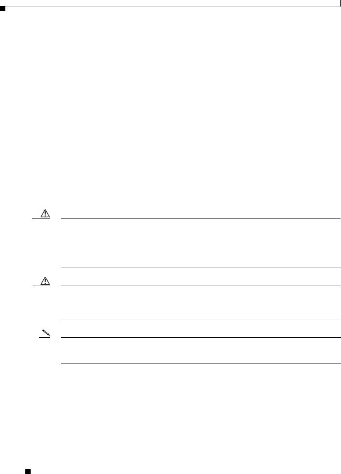
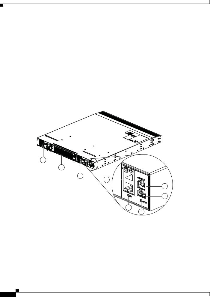
Figure 1-1 shows the front of the Cisco Nexus 3016 chassis and identifies the components that you use to install and connect the chassis. Figure 1-2 shows the rear of the chassis and identifies the components that you use to install and connect the chassis.
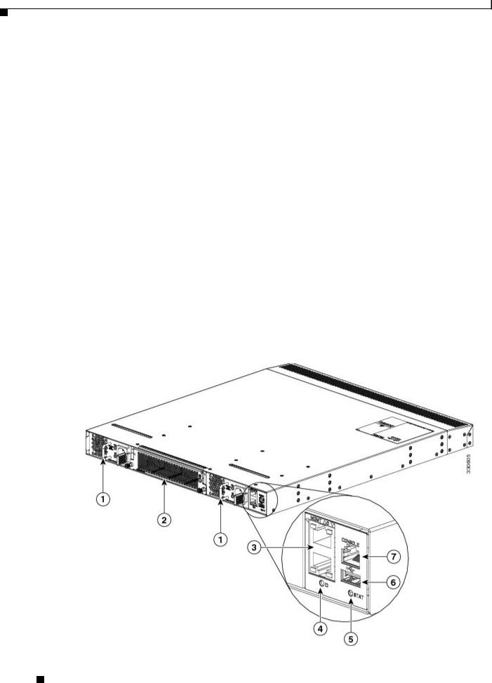
Figure 1-1 Front View of the Cisco Nexus 3016 Switch
Cisco Nexus 3000 Series Hardware Installation Guide
1-2 |
OL-25338-04 |
|
|
Chapter 1 Overview of the Cisco Nexus 3000 Series Switches
Cisco Nexus 3016 Switch
Se n d d o c u m e n t c o m m e n t s t o n ex u s 3 k - d o c f e e d b a ck @ c i s c o . c o m
1 |
AC or DC power supply (2) (AC power supply shown) |
5 |
Status LED |
|
|
|
|
|
|
2 |
Fan tray (1) |
|
6 |
USB port (1) |
|
|
|
|
|
3 |
Management ports (2) |
7 |
Console port (1) |
|
|
|
|
|
|
4 |
ID LED |
|
|
|
|
|
|
|
|
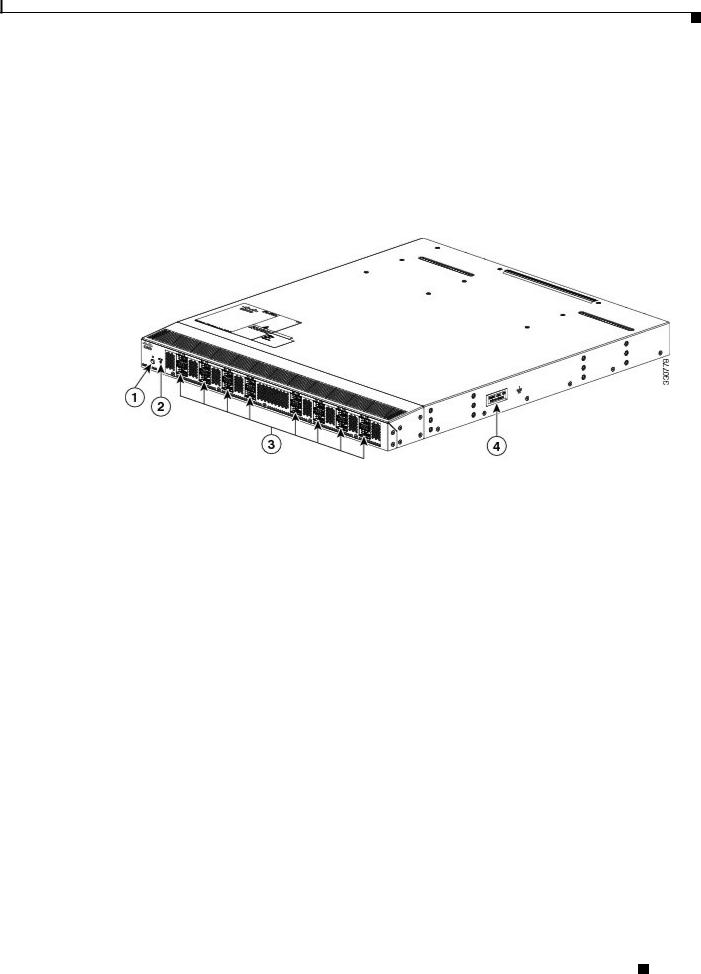
Figure 1-2 |
Rear View of the Cisco Nexus 3016 Switch |
|
|
|
1 |
ID LEDs |
3 |
40-Gigabit uplink or downlink ports (16) |
|
|
|
|
2 |
Status LED |
4 |
Grounding pad |
|
|
|
|
Ports for the Cisco Nexus 3016 Switch
The Cisco Nexus 3016 switch chassis includes the following ports:
•40-Gigabit Ethernet uplink or downlink ports (16 ports)
•100/1000 Ethernet management ports (2 ports)
•Console port (1 port)
•USB port (1 port)
The chassis has 16 40-Gigabit Ethernet ports that you can connect to hosts (uplink connections) or servers (downlink connections), which are often in the same rack or a nearby rack. Each of these ports uses a QSFP+ transceiver which is connected to one or four optical or copper cables. If one cable is used, it has a QSFP+ transceiver on the other end. If four cables are used, each of those cables has an SFP+ transceiver on the other end. The ports are numbered from left to right from 1 to 16 with the odd-numbered ports on top and the even-numbered ports on the bottom.
Two 100/1000 Ethernet management ports enable you to manage switch operations. You can connect to the switch through these two ports by using an RJ-45 connector on a copper cable.
One console port enables you to initially configure the switch and to perform troubleshooting operations. You use an RJ-45 connector with a copper cable to connect to this port.
One USB port enables you to save or load switch configurations.
Cisco Nexus 3000 Series Hardware Installation Guide
|
OL-25338-04 |
1-3 |
|
|
|
Chapter 1 Overview of the Cisco Nexus 3000 Series Switches
Cisco Nexus 3016 Switch
Se n d d o c u m e n t c o m m e n t s t o n ex u s 3 k - d o c f e e d b a ck @ c i s c o . c o m
Power Supply for the Cisco Nexus 3016 Switch
The Cisco Nexus 3000 Series switch has two slots for power supplies that are initially installed with one or two AC or DC power supplies that have forward or reverse airflow for their cooling. The switch requires only one power supply for its operations, but you can include a second one for redundancy.
To determine which part number to use when ordering replacement power supplies, see Table 1-2.
Table 1-2 |
Cisco Nexus 3016 Power Supply Part Numbers |
||
|
|
|
|
Power Source |
|
Airflow Direction |
Power Supply Part Number |
|
|
|
|
AC |
|
Forward |
N2200-PAC-400W= |
|
|
|
|
AC |
|
Reverse |
N2200-PAC-400W-B= |
|
|
|
|
DC |
|
Forward |
N2200-PDC-400W= |
|
|
|
|
DC |
|
Reverse |
N3K-PDC-350W-B= |
|
|
|
|
If the chassis has two power supplies, you can hot swap one of the power supplies during operations. If the chassis has only one power supply, you can install the new power supply in the open slot, turn on that power supply, and then remove the original power supply during operations.
Caution You can order replacement power supplies with forward airflow or reverse airflow. Be sure to order the same direction of airflow as is used with the switch. If there is a black stripe across the front of the fan trays and power supplies, the switch is running reverse airflow and you must order power supplies with reverse airflow (each module has a black stripe). If there is no black stripe across the front of these modules, the switch is running forward airflow and you must order replacement modules with forward airflow (modules that do not have a black stripe).
Caution The switch must run with all of its power supply and fan tray modules taking in air from a cold aisle and exhausting air to the hot aisle. If they take in air from a hot aisle, an overtemperature condition can occur and the switch will shut down. If the airflow directions are mixed in the same switch, you will see an error.
Note Never leave a power supply slot empty. If you remove a power supply, replace it with another one. If you do not have a replacement power supply, leave the non functioning one in place until you can replace it or fill the slot with a filler blank module (part number N2200-P-BLNK).
For power supply specifications, see the “Power Specifications” section on page B-2. For information about the power supply LEDs and what they indicate, see the “Power Supply Status” section on
page D-3.
Cisco Nexus 3000 Series Hardware Installation Guide
1-4 |
OL-25338-04 |
|
|
Chapter 1 Overview of the Cisco Nexus 3000 Series Switches
Cisco Nexus 3016 Switch
Se n d d o c u m e n t c o m m e n t s t o n ex u s 3 k - d o c f e e d b a ck @ c i s c o . c o m
Fan Tray for the Cisco Nexus 3016 Switch
The Cisco Nexus 3016 switch ships with one fan tray, which is the same fan tray used by the Cisco Nexus 3064 switch (part number N3K-C3064-FAN for forward airflow or N3K-C3064-FAN-B for reverse airflow). You can hot swap the fan tray during operations but must replace it within two minutes or the switch can reach an overtemperature condition and shut down.
Caution You can order a replacement fan tray with forward airflow or reverse airflow. Be sure to order the same direction of airflow as is used with the switch. If there is a black stripe across the front of the fan trays and power supplies, the switch is running reverse airflow and you must order a fan tray with reverse airflow. If there is no black stripe across the front of these modules, the switch has forward airflow and you must order replacement modules with forward airflow.
Caution The switch must run with all of its power supply and fan tray modules taking in air from a cold aisle and exhausting air to the hot aisle. If they take in air from a hot aisle, an overtemperature condition can occur and the switch will shut down. If the airflow directions are mixed in the same switch, you will see an error.
Port Connections for the Cisco Nexus 3016 Switch
You use QSFP+ transceivers with the 16 networking ports used for uplinking and downlinking. For low-cost connections to switches in the same or adjacent racks, use QSFP+ transceivers with copper cables. For long distance connections, use the QSFP transceivers connected to optical cables.
Table 1-3 describes the QSFP+ transceivers and cable connections that you can use with the 16 ports used for uplinks and downlinks.
Table 1-3 |
QSFP+ Transceivers and Cables Used with the Cisco Nexus 3016 Switch Uplink and |
|
|
Downlink Ports |
|
|
|
|
Part Number |
|
Transceivers and Cables |
|
|
|
QSFP-40G-SR4 |
40-Gigabit SR4 QSFP transceiver on both ends of an optical cable. Used for |
|
|
|
distances up to 100 meters. |
|
|
|
QSFP-H40G-CU1M |
40-Gigabit transceiver with a 1-meter passive copper cable |
|
|
|
|
QSFP-H40G-CU3M |
40-Gigabit transceiver with a 3-meter passive copper cable |
|
|
|
|
QSFP-H40G-CU5M |
40-Gigabit transceiver with a 5-meter passive copper cable |
|
|
|
|
QSFP-4SFP10G-CU1M |
40-Gigabit transceiver connected to four 1-meter passive copper cables, each |
|
|
|
connected to an SFP+ transceiver |
|
|
|
QSFP-4SFP10G-CU3M |
40-Gigabit transceiver connected to four 3-meter passive copper cables, each |
|
|
|
connected to an SFP+ transceiver |
|
|
|
QSFP-4SFP10G-CU5M |
40-Gigabit transceiver connected to four 5-meter passive copper cables, each |
|
|
|
connected to an SFP+ transceiver |
|
|
|
Cisco Nexus 3000 Series Hardware Installation Guide
|
OL-25338-04 |
1-5 |
|
|
|

Chapter 1 Overview of the Cisco Nexus 3000 Series Switches
Cisco Nexus 3048 Switch
Se n d d o c u m e n t c o m m e n t s t o n ex u s 3 k - d o c f e e d b a ck @ c i s c o . c o m
Cisco Nexus 3048 Switch
The Cisco Nexus 3048 switch is a 1 rack unit (RU) switch that supports 48 fixed 10/100/1000 Ethernet downlink (server-facing) ports, four fixed 10-Gigabit Ethernet uplink (network-facing) ports, two fixed 100/1000 management ports, and one console port. The switch includes one or two AC or DC power supply units and one fan tray module, both of which provide either forward or reverse airflow for cooling. The switch includes a Layer 3 license. To order the appropriate Cisco Nexus 3048 switch bundle, see Table 1-4.
Table 1-4 |
Cisco Nexus 3048 Switch Bundles |
|
||
|
|
|
|
|
Power Supply |
|
Airflow Direction |
Layer 3 License |
Part Number |
|
|
|
|
|
Select when ordering |
Select when ordering |
No |
N3K-C3048TP-1GE |
|
|
|
|
|
|
AC |
|
Forward |
Yes |
N3K-C3048-FA-L3 |
|
|
|
|
|
AC |
|
Reverse |
Yes |
N3K-C3048-BA-L3 |
|
|
|
|
|
DC |
|
Forward |
Yes |
N3K-C3048-FD-L3 |
|
|
|
|
|
DC |
|
Reverse |
Yes |
N3K-C3048-BD-L3 |
|
|
|
|
|
This section includes the following topics:
•Chassis for the Cisco Nexus 3048 Switch, page 1-6
•Ports for the Cisco Nexus 3048 Switch, page 1-8
•Power Supply for the Cisco Nexus 3048 Switch, page 1-9
•Fan Tray for the Cisco Nexus 3048 Switch, page 1-10
•Port Connections for the Cisco Nexus 3048 Switch, page 1-10
Chassis for the Cisco Nexus 3048 Switch
The 1-RU Cisco Nexus 3048 chassis (part number N3K-C3048TP-1GE) is 1.72 inches (4.37 cm) high, 17.3 inches (43.9 cm) wide, and 19.7 inches (50.8 cm) deep. This switch is designed for 19-inch (48.3 cm) racks. Its switch ports are at the rear of the chassis in close proximity to server ports, and the power supplies and fan tray forward airflow or reverse airflow depending on whether the front of the switch is on a cold aisle (forward airflow) or on a hot aisle (reverse airflow). You can also order the switch with AC or DC power supplies.
Fully populated with two power supplies and a fan tray, the switch weighs 20.5 pounds (9.3 kg) and can be easily installed by one or two people.
Figure 1-3 shows the front of the Cisco Nexus 3048 chassis and identifies the components that you use to install and connect the chassis. Figure 1-4 shows the rear of the chassis and identifies the components that you use to install and connect the chassis.
Cisco Nexus 3000 Series Hardware Installation Guide
1-6 |
OL-25338-04 |
|
|
Chapter 1 Overview of the Cisco Nexus 3000 Series Switches
Cisco Nexus 3048 Switch
Se n d d o c u m e n t c o m m e n t s t o n ex u s 3 k - d o c f e e d b a ck @ c i s c o . c o m
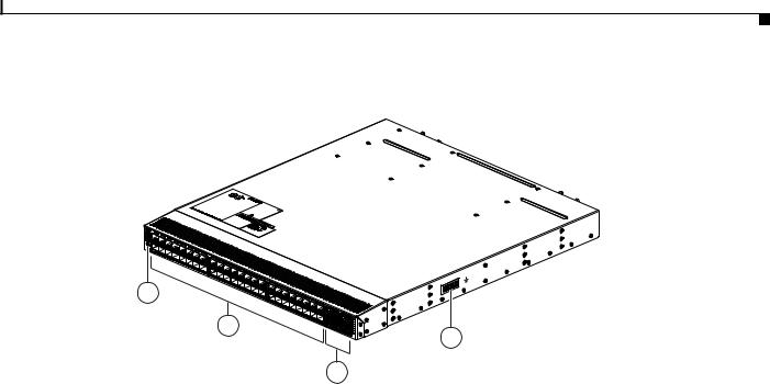
Figure 1-3 Front View of the Cisco Nexus 3048 Switch
1 |
AC or DC power supply (2) (AC power supplies shown) |
5 |
Status LED |
|
|
|
|
2 |
Fan tray (1) |
6 |
USB port (1) |
|
|
|
|
3 |
Management ports (2) |
7 |
Console port (1) |
|
|
|
|
4 |
ID LED |
|
|
|
|
|
|
Cisco Nexus 3000 Series Hardware Installation Guide
|
OL-25338-04 |
1-7 |
|
|
|
Chapter 1 Overview of the Cisco Nexus 3000 Series Switches
Cisco Nexus 3048 Switch
Se n d d o c u m e n t c o m m e n t s t o n ex u s 3 k - d o c f e e d b a ck @ c i s c o . c o m
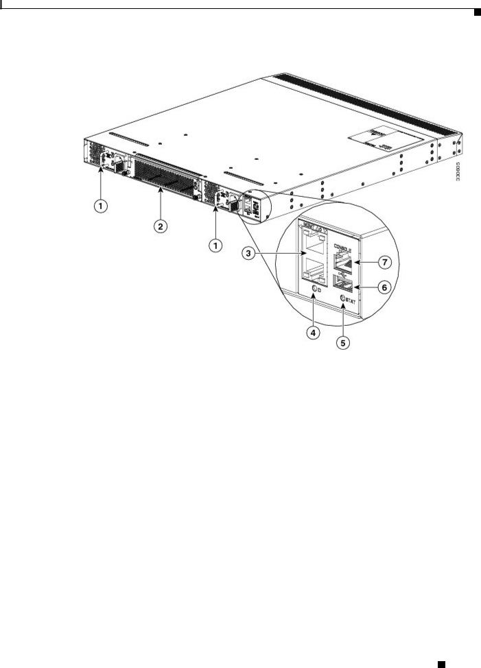
Figure 1-4 Rear View of the Cisco Nexus 3048 Switch
1 |
ID and Status LEDs |
3 |
1- and 10-Gigabit Ethernet uplink ports (4) |
|
|
|
|
2 |
10/100/1000 Ethernet downlink ports (48) |
4 |
Grounding pad |
|
|
|
|
Ports for the Cisco Nexus 3048 Switch
The Cisco Nexus 3048 switch chassis includes the following ports:
•10/100/1000 Ethernet downlink ports (48 ports)
•1- and 10-Gigabit Ethernet uplink ports
•100/1000 Ethernet management ports (2 ports)
•Console port (1 port)
•USB port (1 port)
The chassis has 48 10/100/1000 Ethernet downlink ports that you connect to servers, which are often in the same rack or a nearby rack. You use RJ-45 connectors with copper cables to connect the switch to the servers. The ports are numbered from left to right from 1 to 48 with the odd-numbered ports on top and the even-numbered ports on the bottom.
You use up to four 1- and 10-Gigabit Ethernet uplink ports to connect the switch to one to four hosts or switches. You use an SFP or SFP+ transceiver for each of these ports.
Two 100/1000 Ethernet management ports enable you to manage switch operations. You can connect to the switch through these two ports by using an RJ-45 connector on a copper cable.
One console port enables you to initially configure the switch and to perform troubleshooting operations. You use an RJ-45 connector with a copper cable to connect to this port.
One USB port enables you to save or load switch configurations.
Cisco Nexus 3000 Series Hardware Installation Guide
1-8 |
OL-25338-04 |
|
|

Chapter 1 Overview of the Cisco Nexus 3000 Series Switches
Cisco Nexus 3048 Switch
Se n d d o c u m e n t c o m m e n t s t o n ex u s 3 k - d o c f e e d b a ck @ c i s c o . c o m
Power Supply for the Cisco Nexus 3048 Switch
The Cisco Nexus 3000 Series switch has two slots for power supplies that are initially installed with one or two AC or DC power supplies that have forward or reverse airflow for their cooling. The switch requires only one power supply for its operations, but you can include a second one for redundancy.
To determine which part number to use when ordering replacement power supplies, see Table 1-5.
Table 1-5 |
Cisco Nexus 3048 Power Supply Part Numbers |
||
|
|
|
|
Power Source |
|
Airflow Direction |
Power Supply Part Number |
|
|
|
|
AC |
|
Forward |
N2200-PAC-400W= |
|
|
|
|
AC |
|
Reverse |
N2200-PAC-400W-B= |
|
|
|
|
DC |
|
Forward |
N2200-PDC-400W= |
|
|
|
|
DC |
|
Reverse |
N3K-PDC-350W-B= |
|
|
|
|
If the chassis has two power supplies, you can hot swap one of the power supplies during operations. If the chassis has only one power supply, you can install the new power supply in the open slot, turn on that power supply, and then remove the original power supply during operations.
Caution You can order replacement power supplies with front-to-back airflow or back-to-front airflow. Be sure to order the same direction of airflow as is used with the switch. If there is a black stripe across the front of the fan trays and power supplies, the switch is running back-to-front airflow and you must order power supplies with back-to-front airflow. If there is no black stripe across the front of these modules, the switch is running front-to-back airflow and you must order replacement modules with front-to-back airflow.
Caution The switch must run with all of its power supply and fan tray modules taking in air from a cold aisle and exhausting air to the hot aisle. If they take in air from a hot aisle, an overtemperature condition can occur and the switch will shut down. If the airflow directions are mixed in the same switch, you will see an error.
Note Never leave a power supply slot empty. If you remove a power supply, replace it with another one. If you do not have a replacement power supply, leave the non functioning one in place until you can replace it or fill the slot with a filler blank module (part number N2200-P-BLNK).
For power supply specifications, see the “Power Specifications” section on page B-2. For information about the power supply LEDs and what they indicate, see the “Power Supply Status” section on
page D-3.
Cisco Nexus 3000 Series Hardware Installation Guide
|
OL-25338-04 |
1-9 |
|
|
|
Chapter 1 Overview of the Cisco Nexus 3000 Series Switches
Cisco Nexus 3048 Switch
Se n d d o c u m e n t c o m m e n t s t o n ex u s 3 k - d o c f e e d b a ck @ c i s c o . c o m
Fan Tray for the Cisco Nexus 3048 Switch
The Cisco Nexus 3048 switch ships with one fan tray, which provides forward airflow from the fan tray to the port connector end exhaust (spares part number N3K-C3048-FAN=) or reverse airflow from the port connectors end of the chassis to the fan tray for exhaust (spares part number N3K-C3048-FAN-B). You can hot swap the fan tray during operations but must replace it within two minutes or the switch can reach an overtemperature condition and shut down.
Caution You can order a replacement fan tray with forward airflow or reverse airflow. Be sure to order the same direction of airflow that is used with the switch. If there is a black stripe across the front of the fan trays and power supplies, the switch is running reverse airflow and you must order a fan tray with reverse airflow. If there is no black stripe across the front of these modules, the switch has forward airflow and you must order replacement modules with forward airflow.
Caution The switch must run with all of its power supply and fan tray modules taking in air from a cold aisle and exhausting air to the hot aisle. If they take in air from a hot aisle, an overtemperature condition can occur and the switch will shut down. If the airflow directions are mixed in the same switch, you will see an error.
Port Connections for the Cisco Nexus 3048 Switch
You use RJ-45 connectors with copper cables for the downlink ports, management ports, and console port, and you use SFP or SFP+ transceivers for the uplink ports.
The 4 uplink ports support SFP and SFP+ transceivers that are either connected to copper cables or can be connected to optical cables. Table 1-6 describes the SFP+ transceivers and cable connections that you can use. Table 1-7 describes the SFP transceivers and cable connections that you can use.
Table 1-6 |
SFP Transceivers and Cables for the Cisco Nexus 3048 Switch Uplink Ports |
|
|
|
|
Part Number |
|
Transceivers and Cables |
|
|
|
GLC-T |
|
1000BASE-T SFP transceiver |
|
|
|
GLC-SX-MM |
|
Gigabit Ethernet multimode fiber (MMF) SFP transceiver with an LC connector of |
|
|
type SX |
|
|
|
GLC-LH-SM |
|
Gigabit Ethernet single-mode fiber (SMF) SFP transceiver with an LC connector of |
|
|
type LX/LH |
|
|
|
|
Cisco Nexus 3000 Series Hardware Installation Guide |
1-10 |
OL-25338-04 |

Chapter 1 Overview of the Cisco Nexus 3000 Series Switches
Cisco Nexus 3064 Switch
Se n d d o c u m e n t c o m m e n t s t o n ex u s 3 k - d o c f e e d b a ck @ c i s c o . c o m
Table 1-7 |
SFP+ Transceivers and Cables for the Cisco Nexus 3048 Switch Uplink Ports |
|
|
|
|
Part Number |
|
Transceivers and Cables |
|
|
|
SFP-10G-SR |
|
10-Gigabit Ethernet—short range SFP+ module |
|
|
|
SFP-10G-LR |
|
10-Gigabit Ethernet—long range SFP+ module |
|
|
|
SFP-H10GB-CU1M |
10-Gigabit Ethernet transceiver connected to a passive 1-meter copper cable |
|
|
|
|
SFP-H10GB-CU3M |
10-Gigabit Ethernet transceiver connected to a passive 3-meter copper cable |
|
|
|
|
SFP-H10GB-CU5M |
10-Gigabit Ethernet transceiver connected to a passive 5-meter copper cable |
|
|
|
|
SFP-H10GB-ACU7M |
10-Gigabit Ethernet transceiver connected to an active 7-meter copper cable |
|
|
|
|
SFP-H10GB-ACU10M |
10-Gigabit Ethernet transceiver connected to an active 10-meter copper cable |
|
|
|
|
Cisco Nexus 3064 Switch
The Cisco Nexus 3064 is a 1 rack unit (RU) switch that supports 48 fixed 1- and 10-Gigabit Ethernet host ports, four fixed 40-Gigabit Ethernet network ports, two fixed 100/1000 management ports, and one console port. The switch includes one or two AC or DC power supply units and one fan tray module, both of which provide forward or reverse airflow for cooling. The switch includes a Layer 3 license. The Cisco Nexus 3064 delivers ultra-low nominal latency and supports power-on auto provisioning and consumes low power. To order the appropriate Cisco Nexus 3064 switch bundle, see Table 1-8.
Table 1-8 |
Cisco Nexus 3064 Switch Bundles |
|
||
|
|
|
|
|
Power Supply |
|
Airflow Direction |
Layer 3 License |
Part Number |
|
|
|
|
|
Select when ordering |
Select when ordering |
No |
N3K-C3064PQ-10GE |
|
|
|
|
|
N3K-C3064PQ-10GX |
|
|
|
|
|
AC |
|
Forward |
Yes |
N3K-C3064-E-FA-L3 |
|
|
|
|
N3K-C3064-X-FA-L3 |
|
|
|
|
|
AC |
|
Reverse |
Yes |
N3K-C3064-E-BA-L3 |
|
|
|
|
N3K-C3064-X-BA-L3 |
|
|
|
|
|
DC |
|
Forward |
Yes |
N3K-C3064-E-FD-L3 |
|
|
|
|
N3K-C3064-X-FD-L3 |
|
|
|
|
|
DC |
|
Reverse |
Yes |
N3K-C3064-E-BD-L3 |
|
|
|
|
N3K-C3064-X-BD-L3 |
|
|
|
|
|
This section includes the following topics:
•Chassis for the Cisco Nexus 3064 Switch, page 1-12
•Ports for the Cisco Nexus 3064 Switch, page 1-13
•Power Supply for the Cisco Nexus 3064 Switch, page 1-14
•Fan Tray for the Cisco Nexus 3064 Switch, page 1-14
•Port Connections for the Cisco Nexus 3064 Switch, page 1-15
|
|
Cisco Nexus 3000 Series Hardware Installation Guide |
|
|
|
|
|
|
|||
|
OL-25338-04 |
|
|
1-11 |
|
|
|
|
|
||
Chapter 1 Overview of the Cisco Nexus 3000 Series Switches
Cisco Nexus 3064 Switch
Se n d d o c u m e n t c o m m e n t s t o n ex u s 3 k - d o c f e e d b a ck @ c i s c o . c o m
Chassis for the Cisco Nexus 3064 Switch
The 1-RU Cisco Nexus 3064 chassis (part number N3K-C3064PQ-10GE or N3K-C3064PQ-10GX) is 1.72 inches (4.37 cm) high, 17.3 inches (43.9 cm) wide, and 19.7 inches (45.0 cm) deep. This switch is designed for 19-inch (48.3 cm) racks. Its switch ports are at the rear of the chassis in close proximity to server ports, and the power supplies and fan tray modules are accessible from the front for easy replacement. You can order this switch with forward or reverse airflow depending on whether the front of the switch is in a cold aisle (forward airflow) or in a hot aisle (reverse airflow). You can also order the switch with AC or DC power supplies.
Fully populated with two power supplies and a fan tray, the switch weighs 20.5 pounds (9.3 kg) and can be easily installed by one or two people.
Figure 1-5 shows the front of the chassis and identifies the components that you use to install and connect the chassis. Figure 1-6 shows the rear of the chassis and identifies the components that you use to install and connect the chassis.
Figure 1-5 Front View of the Cisco Nexus 3064 Switch
1
2
1
3
4
5
7
6
239974
1 |
AC or DC power supply (2) (AC power supply shown) |
5 |
Status LED |
|
|
|
|
2 |
Fan tray (1) |
6 |
USB port (1) |
|
|
|
|
3 |
Management ports (2) |
7 |
Console port (1) |
|
|
|
|
4 |
ID LED |
|
|
|
|
|
|
|
Cisco Nexus 3000 Series Hardware Installation Guide |
1-12 |
OL-25338-04 |
Chapter 1 Overview of the Cisco Nexus 3000 Series Switches
Cisco Nexus 3064 Switch
Se n d d o c u m e n t c o m m e n t s t o n ex u s 3 k - d o c f e e d b a ck @ c i s c o . c o m
Figure 1-6 Rear View of the Cisco Nexus 3064 Switch
1
2
4
3
239975
1 |
ID and Status LEDs |
3 |
40-Gigabit Ethernet uplink ports (4) |
|
|
|
|
2 |
1- and 10-Gigabit Ethernet downlink ports (48) |
4 |
Grounding pad |
|
|
|
|
Ports for the Cisco Nexus 3064 Switch
The switch chassis includes the following ports:
•1- and 10-Gigabit Ethernet downlink ports (48 ports)
•40-Gigabit Ethernet uplink ports (4 ports, each handling 4 x 10-Gigabit Ethernet)
•100/1000 Ethernet management ports (2 ports)
•Console port (1 port)
•USB port (1 port)
The chassis has 48 1- and 10-Gigabit Ethernet downlink ports that you connect to servers, which are often in the same rack or a nearby rack. You use Small Form factor Pluggable Plus (SFP+) transceivers with copper or optical cables to connect the switch to the servers. The ports are numbered from left to right from 1 to 48 with the odd-numbered ports on top and the even-numbered ports on the bottom.
You use up to four 40-Gigabit Ethernet uplink ports to connect the switch to one to four hosts or switches. You use a Quad SFP+ (QSFP+) transceiver for each of these ports. That transceiver is either already connected to four copper cables, each handling 10 Gigabits of data, with a SFP+ transceiver on each cable, or you connect an optical cable to the QSFP+ transceiver and to another QSFP+ transceiver on another switch.
Two 100/1000 Ethernet management ports enable you to manage switch operations. You can connect to the switch through these two ports by using an RJ-45 connector on a copper cable.
One console port enables you to initially configure the switch and to perform troubleshooting operations. You use an RJ-45 connector with a copper cable to connect to this port.
One USB port enables you to save or load switch configurations.
|
|
Cisco Nexus 3000 Series Hardware Installation Guide |
|
|
|
|
|
|
|||
|
OL-25338-04 |
|
|
1-13 |
|
|
|
|
|
||
Chapter 1 Overview of the Cisco Nexus 3000 Series Switches
Cisco Nexus 3064 Switch
Se n d d o c u m e n t c o m m e n t s t o n ex u s 3 k - d o c f e e d b a ck @ c i s c o . c o m
Power Supply for the Cisco Nexus 3064 Switch
The Cisco Nexus 3000 Series switch has two slots for power supplies that are initially installed with one or two AC or DC power supplies that have forward or reverse airflow for their cooling. The switch requires only one power supply for its operations, but you can include a second one for redundancy.
To determine which part number to use when ordering replacement power supplies, see Table 1-9.
Table 1-9 |
Cisco Nexus 3064 Power Supply Part Numbers |
||
|
|
|
|
Power Source |
|
Airflow Direction |
Power Supply Part Number |
|
|
|
|
AC |
|
Forward |
N2200-PAC-400W= |
|
|
|
|
AC |
|
Reverse |
N2200-PAC-400W-B= |
|
|
|
|
DC |
|
Forward |
N2200-PDC-400W= |
|
|
|
|
DC |
|
Reverse |
N3K-PDC-350W-B= |
|
|
|
|
If the chassis has two power supplies, you can hot swap one of the power supplies during operations. If the chassis has only one power supply, you can install the new power supply in the open slot, turn on that power supply, and then remove the original power supply during operations.
Caution You can order replacement power supplies with front-to-back airflow or back-to-front airflow. Be sure to order the same direction of airflow as is used with the switch. If there is a black stripe across the front of the fan trays and power supplies, the switch is running back-to-front airflow and you must order power supplies with back-to-front airflow. If there is no black stripe across the front of these modules, the switch is running front-to-back airflow and you must order replacement modules with front-to-back airflow.
Caution The switch must run with all of its power supply and fan tray modules taking in air from a cold aisle and exhausting air to the hot aisle. If they take in air from a hot aisle, an overtemperature condition can occur and the switch will shut down. If the airflow directions are mixed in the same switch, you will see an error.
Note Never leave a power supply slot empty. If you remove a power supply, replace it with another one. If you do not have a replacement power supply, leave the non functioning one in place until you can replace it or fill the slot with a filler blank module (part number N2200-P-BLNK).
For power supply specifications, see the “Power Specifications” section on page B-2. For information about the power supply LEDs and what they indicate, see the “Power Supply Status” section on
page D-3.
Fan Tray for the Cisco Nexus 3064 Switch
The Cisco Nexus 3064 switch ships with one fan tray, which provide either forward or reverse airflow for cooling. You can hot swap the fan tray during operations but must replace it within two minutes or the switch can reach an overtemperature condition and shut down.
|
Cisco Nexus 3000 Series Hardware Installation Guide |
1-14 |
OL-25338-04 |
Loading...