


 Loading...
Cisco 10005 ESR DC Power Entry
Module Installation
March 30, 2001
This installation note provides procedures for installing and replacing DC power entry modules (PEMs) in a Cisco 10005 edge services router (ESR).
Contents
The following sections are included in this installation note:
•Product Description, page 2
•Prerequisites and Preparation, page 2
•Adding or Replacing a DC PEM, page 8
•FCC Class B Compliance, page 20
•Related Documentation, page 21
•Obtaining Documentation, page 22
•Obtaining Technical Assistance, page 23
Corporate Headquarters: Cisco Systems, Inc., 170 West Tasman Drive, San Jose, CA 95134-1706 USA
Copyright © 2001. Cisco Systems, Inc. All rights reserved. |
78-12653-01 |

Product Description
Product Description
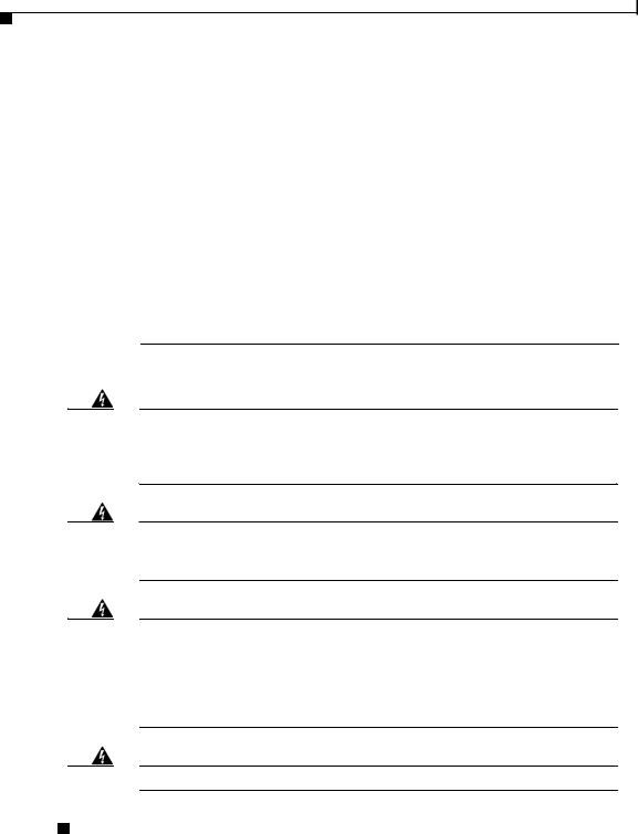
The DC PEM (Figure 1) provides filtering and supplies DC power to the chassis electronics. The DC PEM receives input power (–48 VDC from building centralized power source) through terminal block connections located on the front panel of the PEM.
Figure 1 |
DC PEM |
ATCATUETNIOTNIO:NU:SNE'UCTOILPISPEEZR QCUOENDDUESCTCOORNSDOUNCLTYEURS EN |
CAUTIO |
||
|
|
CURVE |
|
|
|
|
BREAKENR: TAENRDMRINEAMLOSVMEAPYOBE ENERGIZ |
|
|
|
WERSUPPLYEBDE. TFUORRNE OACFFCEPSOSWINEGR TSEORUMRCE CIRCUIT |
|
|
|
INALS. GML |
|
THIS |
CAUTION |
|
|
SUPPULYNITCOHAS MORE T |
INPUT |
|
|
SERPOWVEICR SUPRPDL.YDCISOCONNHAENCTOTNWE POWER |
||
|
|
ING TO AVOIDRDESLEBCETFROICRESOH(2O)CK. |
-48/60 V |
POWER |
|
MISWIRE |
35A |
FAULT |
|
||
53615
The Cisco 10005 chassis has two compartments for PEMs. The chassis can operate with a single PEM; install two PEMs if you require power redundancy.
Prerequisites and Preparation
Before you perform any of the procedures in this guide, we recommend that you:
•Read the safety guidelines in the next section and review the electrical safety and ESD-prevention guidelines in the Cisco 10005 ESR Hardware Installation Guide.
•Ensure that you have all of the necessary tools and equipment (see the “Required Tools and Equipment” section on page 7).
•Have access to the following documents during the installation:
–Technology of Edge Aggregation: Cisco 10000 Series Edge Services Router (shipped with your router and available for viewing or download at Cisco.com)
Cisco 10005 ESR DC Power Entry Module Installation
2 |
78-12653-01 |
|
|

Prerequisites and Preparation
–Cisco 10005 ESR Hardware Installation Guide (shipped with your router and available for viewing or download at Cisco.com)
–Cisco 10000 Series ESR Troubleshooting Guide (an online document available for viewing or download at Cisco.com)
–Cisco 10000 Series ESR Software Configuration Guide (an online document available for viewing or download at Cisco.com)
Safety Guidelines
Before you begin the installation or replacement procedure, review the safety guidelines in this section to avoid injuring yourself or damaging the equipment.
Safety Warnings
Safety warnings appear throughout this publication in procedures that, if performed incorrectly, might harm you. A warning symbol precedes each warning statement.
Before you install, configure, or perform maintenance on the router, review the documentation for the procedure you are about to perform, paying special attention to the safety warnings. If you need translations of the safety warnings, refer to the “Translated Safety Warnings” appendix of the Cisco 10005 ESR Hardware Installation Guide.
Cisco 10005 ESR DC Power Entry Module Installation
|
78-12653-01 |
3 |
|

Prerequisites and Preparation
Warning This warning symbol means danger. You are in a situation that could cause bodily injury. Before you work on any equipment, be aware of the hazards involved with electrical circuitry and be familiar with standard practices for preventing accidents. (To see translations of the warnings that appear in this publication, refer to the appendix “Translated Safety Warnings” in the installation guide that accompanied this device.)
Waarschuwing Dit waarschuwingssymbool betekent gevaar. U verkeert in een situatie die lichamelijk letsel kan veroorzaken. Voordat u aan enige apparatuur gaat werken, dient u zich bewust te zijn van de bij elektrische schakelingen betrokken risico’s en dient u op de hoogte te zijn van standaard maatregelen om ongelukken te voorkomen. (Voor vertalingen van de waarschuwingen die in deze publicatie verschijnen, kunt u het aanhangsel “Translated Safety Warnings” (Vertalingen van veiligheidsvoorschriften) in de installatiegids die bij dit toestel is ingesloten, raadplegen.
Varoitus Tämä varoitusmerkki merkitsee vaaraa. Olet tilanteessa, joka voi johtaa ruumiinvammaan. Ennen kuin työskentelet minkään laitteiston parissa, ota selvää sähkökytkentöihin liittyvistä vaaroista ja tavanomaisista onnettomuuksien ehkäisykeinoista. (Tässä julkaisussa esiintyvien varoitusten käännökset löydät tämän laitteen mukana olevan asennusoppaan liitteestä "Translated Safety Warnings" (käännetyt turvallisuutta koskevat varoitukset).)
Attention Ce symbole d’avertissement indique un danger. Vous vous trouvez dans une situation pouvant entraîner des blessures. Avant d’accéder à cet équipement, soyez conscient des dangers posés par les circuits électriques et familiarisez-vous avec les procédures courantes de prévention des accidents. Pour obtenir les traductions des mises en garde figurant dans cette publication, veuillez consulter l’annexe intitulée
« Translated Safety Warnings » (Traduction des avis de sécurité) dans le guide d’installation qui accompagne cet appareil.
Cisco 10005 ESR DC Power Entry Module Installation
4 |
78-12653-01 |
|
|

Prerequisites and Preparation
Warnung Dieses Warnsymbol bedeutet Gefahr. Sie befinden sich in einer Situation, die zu einer Körperverletzung führen könnte. Bevor Sie mit der Arbeit an irgendeinem Gerät beginnen, seien Sie sich der mit elektrischen Stromkreisen verbundenen Gefahren und der Standardpraktiken zur Vermeidung von Unfällen bewußt. (Übersetzungen der in dieser Veröffentlichung enthaltenen Warnhinweise finden Sie im Anhang mit dem Titel “Translated Safety Warnings” (Übersetzung der Warnhinweise) in der diesem Gerät beiliegenden Installationsanleitung.)
Avvertenza Questo simbolo di avvertenza indica un pericolo. Si è in una situazione che può causare infortuni. Prima di lavorare su qualsiasi apparecchiatura, occorre conoscere i pericoli relativi ai circuiti elettrici ed essere al corrente delle pratiche standard per la prevenzione di incidenti. La traduzione delle avvertenze riportate in questa pubblicazione si trova nell’appendice, “Translated Safety Warnings” (Traduzione delle avvertenze di sicurezza), del manuale d’installazione che accompagna questo dispositivo.
Advarsel Dette varselsymbolet betyr fare. Du befinner deg i en situasjon som kan føre til personskade. Før du utfører arbeid på utstyr, må du være oppmerksom på de faremomentene som elektriske kretser innebærer, samt gjøre deg kjent med vanlig praksis når det gjelder å unngå ulykker. (Hvis du vil se oversettelser av de advarslene som finnes i denne publikasjonen, kan du se i vedlegget "Translated Safety Warnings" [Oversatte sikkerhetsadvarsler] i installasjonsveiledningen som ble levert med denne enheten.)
Aviso Este símbolo de aviso indica perigo. Encontra-se numa situação que lhe poderá causar danos fisicos. Antes de começar a trabalhar com qualquer equipamento, familiarize-se com os perigos relacionados com circuitos eléctricos, e com quaisquer práticas comuns que possam prevenir possíveis acidentes. (Para ver as traduções dos avisos que constam desta publicação, consulte o apêndice “Translated Safety Warnings” - “Traduções dos Avisos de Segurança”, no guia de instalação que acompanha este dispositivo).
Cisco 10005 ESR DC Power Entry Module Installation
|
78-12653-01 |
5 |
|
Prerequisites and Preparation
¡Advertencia! Este símbolo de aviso significa peligro. Existe riesgo para su integridad física. Antes de manipular cualquier equipo, considerar los riesgos que entraña la corriente eléctrica y familiarizarse con los procedimientos estándar de prevención de accidentes. (Para ver traducciones de las advertencias que aparecen en esta publicación, consultar el apéndice titulado “Translated Safety Warnings,” en la guía de instalación que se acompaña con este dispositivo.)
Varning! Denna varningssymbol signalerar fara. Du befinner dig i en situation som kan leda till personskada. Innan du utför arbete på någon utrustning måste du vara medveten om farorna med elkretsar och känna till vanligt förfarande för att förebygga skador. (Se förklaringar av de varningar som förekommer i denna publikation i appendix "Translated Safety Warnings" [Översatta säkerhetsvarningar] i den installationshandbok som medföljer denna anordning.)
Warning Before working on equipment that is connected to power lines, remove jewelry (including rings, necklaces, and watches). Metal objects will heat up when connected to power and ground and the heat can cause serious burns or weld the metal object to the terminals.
Warning This product requires short-circuit (overcurrent) protection to be provided as part of the building installation. Install only in accordance with national and local wiring regulations.
Warning Only a DC power source that is isolated from AC mains with reinforced insulation, and that complies with the other safety extra-low voltage (SELV) requirements in UL1950, CSA 950 3rd Edition, EN 60950, and IEC950, can be connected to a Cisco 10005 system. This requirement ensures that in a catastrophic power source fault condition, hazardous voltages are not present on power terminals and connectors.
Warning Use copper conductors only.
Cisco 10005 ESR DC Power Entry Module Installation
6 |
78-12653-01 |
|
|

Prerequisites and Preparation
Required Tools and Equipment
Table 1 lists the tools and equipment you need to install a DC PEM.
Table 1 |
Tools and Equipment |
|
|
|
|
|
|
||
Quantity |
Description |
Comments |
||
|
|
|
||
1 |
Antistatic wrist or ankle strap |
Prevents damage to equipment |
||
|
with connection cord |
from electrostatic discharge |
||
|
|
(ESD). |
|
|
|
|
|
|
|
1 |
Number 2 phillips screwdriver |
|
|
— |
|
|
|
||
1 |
Flat-blade screwdriver. We |
Blade should measure 1.0 mm |
||
|
recommend a torque-limiting |
thick by 4.0 mm wide. An |
||
|
screwdriver. |
appropriate screwdriver is |
||
|
|
available from Phoenix Contact |
||
|
|
Inc. of Harrisburg, PA, USA. |
||
|
|
|
||
1 |
Wire stripping tool |
Choose a tool that does not nick |
||
|
|
the internal wire. |
||
|
|
|
|
|
2 or 4 |
Tie wraps |
|
|
— |
|
|
|
|
|
1 |
Metric measuring tape or ruler |
|
|
— |
|
|
|
|
|
1 |
Marking pen |
|
|
— |
|
|
|
|
|
1 |
Voltmeter |
|
|
— |
|
|
|
||
3 or 6 |
6 AWG (recommended) copper |
The wires must meet these |
||
(length |
wires long enough to reach from |
specifications: |
||
varies) |
the Cisco 10005 chassis to the |
• Conductor size 6 AWG or |
||
|
DC power source. |
|||
|
|
8 AWG (6 AWG preferred) |
||
|
|
|
||
|
• Three wires (two power, one |
• |
Diameter: |
|
|
ground) are needed for a |
|||
|
|
– |
Minimum: 3.38 mm |
|
|
single DC power source. |
|
||
|
• Six wires (four power, two |
|
– |
Maximum: 4.52 mm |
|
ground) are needed for two |
• |
Multistranded copper |
|
|
DC power sources. |
|||
|
|
construction |
||
|
|
|
||
|
|
|
|
|
Cisco 10005 ESR DC Power Entry Module Installation
|
78-12653-01 |
7 |
|
Adding or Replacing a DC PEM
Adding or Replacing a DC PEM
This section describes how to add or replace a DC PEM in a Cisco 10005 chassis. It contains these procedures:
•Installing a Second DC PEM
•Replacing a DC PEM
•Wiring a DC PEM
•Troubleshooting the Installation
Note Before you perform any of the procedures in this document, be sure that you have connected the chassis to earth ground as described in the
Cisco 10005 ESR Hardware Installation Guide.
Installing a Second DC PEM
Warning Never install an AC power module and a DC power module in the same chassis.
Follow these step to install a second DC PEM for redundancy.
Caution Do not power off the DC PEM that is providing power to the router. If you do so, all data traffic halts.
Step 1 Put on an antistatic wrist or ankle strap. Connect the strap to the ESD jack on the front of the chassis or to a bare metal surface of the chassis.
Step 2 Ensure that the power switch on the new DC PEM is set to 0 (Off).
Step 3 Insert the new DC PEM (Figure 2) all the way into the power bay to ensure a secure connection to the midplane. Tighten the captive screws.
Cisco 10005 ESR DC Power Entry Module Installation
8 |
78-12653-01 |
|
|
Loading...