


 Loading...
Cisco 10000 ESR
AC Power Entry Module Installation
This publication contains instructions for installing the AC Power Entry Module (PEM) in the Cisco 10000 Edge Services Router (ESR). If you are not familiar with the Cisco 10000 router, see the Cisco 10000 ESR System Description, and the Cisco 10000 ESR Hardware Installation Guide for additional information.
Contents
The following sections are included in this configuration guide:
•Product Description, page 2
•Prerequisites and Preparation, page 3
•Installation Guidelines, page 4
•Adding or Replacing an AC PEM, page 5
•FCC Class A Compliance, page 20
•Cisco Connection Online, page 20
•Documentation CD-ROM, page 22
Corporate Headquarters: Cisco Systems, Inc., 170 West Tasman Drive, San Jose, CA 95134-1706 USA
Copyright © 2000. Cisco Systems, Inc. All rights reserved. |
78-10832-01 |
Product Description
Product Description
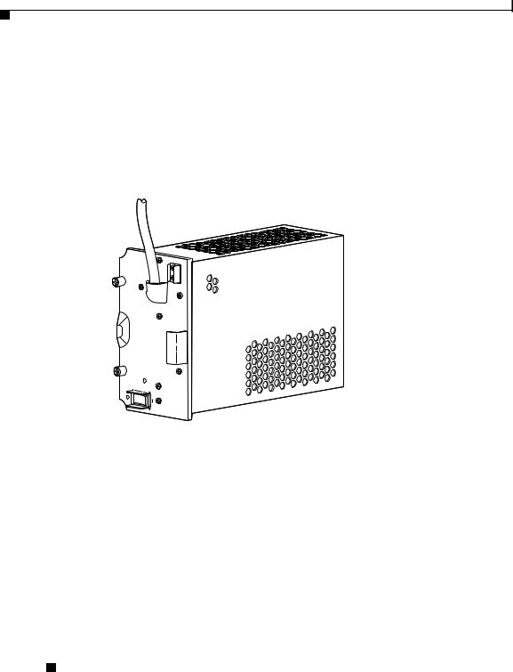
The AC PEM provides power conversion directly from the facility VAC input power (100 VAC to 240 VAC) to the –48V VDC used internally by the system (see Figure 1). AC power is delivered to the AC PEM from the VAC connection power cable to the power cord attached to the PEM.
Figure 1 |
AC PEM |
POWER  FAULT
FAULT
30004
There are two PEM bays in the chassis; however, you only need one PEM to power the router. You can install an additional PEM for power redundancy.
Cisco 10000 ESR AC Power Entry Module Installation
2 |
78-10832-01 |
|
|

Prerequisites and Preparation
Prerequisites and Preparation
Before you perform any of the procedures in this guide, Cisco recommends that you:
•Read the safety guidelines in the next section and review the electrical safety and ESD-prevention guidelines in the Cisco 10000 ESR Hardware Installation Guide.
•Ensure that you have all of the necessary tools and equipment before beginning the installation (see the “Installation Guidelines” section on page 4).
•Have access to the following documents (shipped with your Cisco 10000 system) during the installation:
–Cisco 10000 ESR System Description
–Cisco 10000 ESR Hardware Installation Guide
–Cisco 10000 ESR Troubleshooting Guide
–Cisco 10000 ESR Software Configuration Guide
Safety Guidelines
Before you begin the installation or replacement procedure, review the safety guidelines in this section to avoid injuring yourself or damaging the equipment. Before you install, configure, or perform maintenance on the router, you should also review the safety warnings listed in the Cisco 10000 ESR Hardware Installation Guide.
Safety Warnings
Safety warnings appear throughout this publication in procedures that, if performed incorrectly, may harm you. A warning symbol precedes each warning statement. The following warning is an example of a safety warning. It identifies the warning symbol and associates it with a bodily injury hazard.
Cisco 10000 ESR AC Power Entry Module Installation
|
78-10832-01 |
3 |
|

Installation Guidelines
Warning This warning symbol means danger. You are in a situation that could cause bodily injury. Before you work on any equipment, be aware of the hazards involved with electrical circuitry and be familiar with standard practices for preventing accidents. To see translations of the warnings that appear in this publication, refer to the Regulatory Compliance and Safety Information document that accompanied this device.
Note If you need translations of the safety warning, see the Cisco 10000
ESR Hardware Installation Guide.
Installation Guidelines
The Cisco 10000 system is hot-swappable, which means you can remove and replace a defective PEM while the system is operating (assuming that your system has a second AC PEM installed for redundancy). It is not necessary to notify the software or reset the system power. This feature lets you add, remove, or replace a second PEM while the system maintains all routing information and ensures session preservation.
Required Tools and Equipment
You need the following tools and equipment to install an AC PEM:
•A Number 2 Phillips screwdriver
•3/16-inch flat-blade screwdriver
•An electrostatic discharge (ESD) preventive wrist or ankle strap with connection cord
Cisco 10000 ESR AC Power Entry Module Installation
4 |
78-10832-01 |
|
|
Adding or Replacing an AC PEM
Adding or Replacing an AC PEM
This section describes how to add or replace an AC PEM in the Cisco 10000 chassis. It contains the following procedures:
•Removing the Front Cover, page 5
•Installing a Second AC PEM, page 7
•Replacing an AC PEM, page 12
•Troubleshooting the Installation, page 19
Removing the Front Cover
Use the following procedure to remove the front cover from the system. If your system does not use a front cover, go to the “Installing a Second AC PEM” section on page 7 or to the “Replacing an AC PEM” section on page 12.
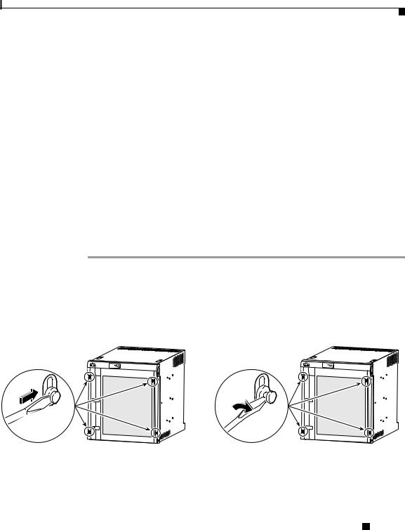
Step 1 Unlock each bezel plug by inserting the tip of a flat-blade screwdriver between the top and bottom sections of the plug, and then rotating the screwdriver to unlock the top portion of the plug (Figure 2).
Repeat this procedure for all four bezel plugs and then remove the plugs.
Figure 2 Unlocking the Bezel Plugs
FANS OK
FAN FAILURE
MULTI-FAN FAILURE
 POWER
POWER
 FAULT
FAULT
 MISWIRE
POWER |
POWER |
FAULT |
FAULT |
MISWIRE |
MISWIRE |
Cisco 10000
30038
FANS OK
FAN FAILURE
MULTI-FAN FAILURE
 POWER
POWER
 FAULT
FAULT
 MISWIRE
 POWER
POWER
 FAULT
FAULT
 MISWIRE
Cisco 10000
30039
Cisco 10000 ESR AC Power Entry Module Installation
|
78-10832-01 |
5 |
|

Adding or Replacing an AC PEM
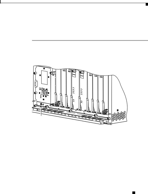
Step 2 Remove the cover by lifting it up slightly and then pulling it toward you (Figure 3).
Figure 3 Removing the Front Cover
FANS OK |
||
FAN |
FAILURE |
|
M |
|
|
|
ULTI-FAN |
|
|
|
FAILURE |
 POWER
POWER  FAULT MISWIRE
 POWER FAULT MISWIRE
POWER FAULT MISWIRE
POWER FAULT MISWIRE
1
CISCO 10000
F
A
IL
L
IN
T K R X X
FANS |
FAN |
|
OK |
MFUALNTI- |
|
|
FAILURE |
|
|
|
FAILURE |
When hot CAUTION |
|
|
||||
|
swapping |
this |
|
|||
removal and |
|
|
|
|||
be done in |
|
replacementfan tray, |
||||
system |
|
under |
|
must |
||
|
|
|
two minutes |
or |
||
|
shutdown will occur. |
|||||
2 |
3 |
|
|
|
|
|
4 |
||
Cisco |
|
|||
10000 |
||||
CISCO |
|
|||
10000 |
CISCO |
C10000CISCO |
||
FA |
10000 |
|||
IL |
AIL |
|
100006CT3 |
|
F |
|
|
||
|
|
|
FAIL |
|
|
|
|
FAIL |
|
|
CAR |
|
|
|
|
RALA |
|
C |
|
|
IERRMLOOP |
|
ARAL |
|
|
0 |
|
RIERARLO |
|
|
|
M OP |
||
|
|
|
PORT00 |
|
|
1 |
|
PORT11 |
|
2 |
|
PORT22 |
|
3 |
CA |
PORT33 |
RR AL |
|
IE AR LO |
|
R |
M OP |
|
4 |
|
PORT44 |
0A |
|
|
|
|
|
PROCESSOR |
|
0B |
5 |
||
|
|
|
ONLY |
||
CISCO |
|
|
|
|
|
10000 |
|
CISCO |
|
||
|
|
10000 |
C10000CISCO |
||
|
|
|
|
|
100006CT3 |
|
|
|
|
|
F |
|
|
|
|
|
AIL |
|
CONSOLE |
|
|
CONSOLE |
FAIL |
|
AUX |
|
|
|
|
|
|
|
|
AUX |
|
|
ACTIVITY |
|
|
|
RLA LO |
|
LINKETHERNET |
|
|
ACTIVITY |
C |
|
|
|
|
|
AR A |
|
|
|
|
LINKETHERNET |
IERRMOP |
AC |
|
|
PORT00 |
||
LINK |
TIV |
|
|
AC |
|
|
IT |
|
L |
|
|
YIN T K IV
ITY
ALARMS |
PORT11 |
|
CRITICAL |
ALARMS |
C |
MAJOR |
RITICAL |
PORT22 |
MINO |
MAJOR |
|
R |
MINOR |
|
ACO |
|
|
|
ACO |
PORT33 |
6
C10000CISCO
100006CT3
FA
IL
FAIL
C
A
R A
LA
LO
IE
R
R O
M
P
PORT00
PORT11 |
PORT22 |
PORT33 |
5 |
PORT44 |
PORT55 |
PORT44 |
|
PORT55 |
|
PORT55 |
7
C10000CISCO
100006CT3
F
AIL
FAIL
C
A
AL
RR
A
LO
IE
R
R O
M
P
PORT00
PORT11 |
PORT22 |
PORT33 |
8
CISCO 10000
10000
FAIL
C
A
R
R
IE
PORT44 |
R TX R |
X |
PORT55 |
|
|
|
|
SL |
|
|
|
|
|
|
|
|
|
|
OT |
|
|
|
|
|
|
|
|
|
|
0 |
|
SL |
|
|
|
|
|
|
|
|
STATUS |
|
OT |
|
|
|
|
|
|
|
|
|
0 |
|
|
|
|
|
|
|
|
|
FAIL |
|
STATUS |
|
|
|
|
|
|
|
|
|
|
|
|
|
|
|
|
|
|
|
|
|
FAIL |
|
|
|
|
ETHERNET GIGABIT |
IR-SM DSO-12-OC CH |
DS0–6XCT3 |
DS0–6XCT3 |
BITS |
ENGINEROUTINGPERFORMANCE |
ENGINEROUTINGPERFORMANCE |
DS0–6XCT3 |
DS0–6XCT3 |
DS0–6XCT3 |
IR–SMPOS4–12/STM–OC |
P/N |
||||||||||
|
|
|
|
|
|
BITS |
|
|
|
|
|
|
|
|
PRE3-ESR |
|
PRE3-ESR P/N |
|
|
|
|
|
|
|
|
PROCESSOR |
|
|
|
|
||
|
|
|
|
|
|
ONLY |
|
|
|
|
30040
Step 3 Continue installing or replacing the AC PEM:
•If you are installing a second AC PEM, go to the “Installing a Second AC PEM” section on page 7.
•If you are replacing an AC PEM, go to the “Replacing an AC PEM” section on page 12.
Cisco 10000 ESR AC Power Entry Module Installation
6 |
78-10832-01 |
|
|
Adding or Replacing an AC PEM
Installing a Second AC PEM
Use the following procedure to install a second AC PEM in the bottom power bay for redundancy.
Step 1 Attach an antistatic wrist strap to your wrist and to an ESD socket on the chassis, or to a bare metal surface on the chassis or frame (Figure 4).
Figure 4 ESD Chassis Connection
ESD socket
32236
Cisco 10000 ESR AC Power Entry Module Installation
|
78-10832-01 |
7 |
|
Loading...