


 Loading...
Cisco 5700 Series Wireless Controller
Installation Guide
This guide is designed to help you install and minimally configure your Cisco 5700 Series Wireless Controller.
•Compliance and Safety Information, page 1
•Controller Overview, page 3
•Unpacking and Installing the Controller, page 10
•Using the Startup Wizard, page 22
•Power Supply Installation, page 25
•Installing a Fan Module, page 30
•Specifications, page 32
•Cisco 90-Day Limited Hardware Warranty Terms, page 33
•Obtaining Documentation and Submitting a Service Request, page 34
Compliance and Safety Information
FCC Safety Compliance Statement
Modifying the equipment without Cisco’s authorization may result in the equipment no longer complying with FCC requirements for Class A digital devices. In that event, your right to use the equipment may be limited by FCC regulations, and you may be required to correct any interference to radio or television communications at your own expense.
Americas Headquarters:
Cisco Systems, Inc., 170 West Tasman Drive, San Jose, CA 95134-1706 USA
Compliance and Safety Information
This equipment has been tested and found to comply with the limits for a Class A digital device, pursuant to Part 15 of the FCC Rules. These limits are designed to provide reasonable protection against harmful interference when the equipment is operated in a commercial environment. This equipment generates, uses, and can radiate radio frequency energy and, if not installed and used in accordance with the instruction manual, may cause harmful interference to radio communications. Operation of this equipment in a residential area is likely to cause harmful interference in which case users will be required to correct the interference at their own expense.
Try to correct the interference by one or more of the following measures:
•Verify that the ambient temperature remains between 32 to 104° F (0 to 40° C), taking into account the elevated temperatures when installed in a rack or enclosed space.
•When multiple Cisco 5700 Series Wireless Controllers are mounted in an equipment rack, be sure that the power source is sufficiently rated to safely run all the equipment in the rack.
•Verify the integrity of the electrical ground before installing the controller.
Safety Information
Safety warnings appear throughout this guide in procedures that may harm you if performed incorrectly. A warning symbol precedes each warning statement. The warnings below are general warnings that apply to the entire guide. Translated versions of the safety warnings in this guide are provided in the
Regulatory Compliance and Safety Information for the Cisco 5700 Series Wireless Controller document that accompanies this guide.
Warning IMPORTANT SAFETY INSTRUCTIONS
This warning symbol means danger. You are in a situation that could cause bodily injury. Before you work on any equipment, be aware of the hazards involved with electrical circuitry and be familiar with standard practices for preventing accidents. Use the statement number provided at the end of each warning to locate its translation in the translated safety warnings that accompanied this device.
Statement 1071
SAVE THESE INSTRUCTIONS
Warning This equipment must be grounded. Never defeat the ground conductor or operate the equipment in the absence of a suitably installed ground conductor. Contact the appropriate electrical inspection authority or an electrician if you are uncertain that suitable grounding is available. Statement 1024
Statement 372—Wireless LAN Products
All wireless LAN products in the 5.2/5.3GHz band cannot be used outdoors. Use the product only indoors.
Cisco 5700 Series Wireless Controller Installation Guide
2 |
OL-28544-01 |
|
|

Controller Overview
Statement 191—VCCI Class A Warning for Japan
Warning This is a Class A product based on the standard of the VCCI Council. If this equipment is used in a domestic environment, radio interference may occur, in which case, the user may be required to take corrective actions.
VCCI-A
Controller Overview
The Cisco 5700 Series Wireless Controller, designed for 802.11n performance and maximum scalability, supports up to 1000 access points and 12000 clients, making it ideal for large-sized enterprises and high-density applications. A core component of the Cisco unified wireless solution, this controller delivers wireless security, intrusion detection, radio management, quality of service (QoS), and mobility across an entire enterprise. The controller works in conjunction with other controllers, Cisco Prime Infrastructure, and access points to provide network managers with a robust wireless LAN solution.
To best use this guide, you should have already designed the wireless topology of your network. Because the Radio Resource Management (RRM) feature automatically detects and configures access points as they appear on the network, it is not necessary to have any access points on the network in order to install and configure a controller.
Figure 1 and Figure 2 show the front panel and back panel of the Cisco 5700 Series Wireless Controller.
Figure 1 |
Front Panel |
Cisco 5700 Series Wireless Controller Installation Guide
|
OL-28544-01 |
3 |
|
|
|
Controller Overview
1 |
Mode button |
4 |
USB port (Type A) |
|
|
|
|
2 |
System LEDs |
5 |
1/10G SFP+ ports |
|
|
|
|
3 |
USB mini-Type B (console) port |
|
|
|
|
|
|
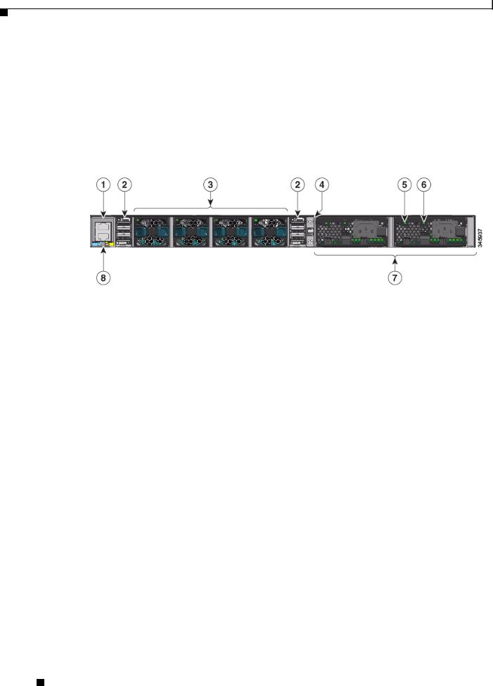
Figure 2 |
Back Panel |
1 |
Console (RJ-45 console port) |
5 |
AC OK (input) status LED |
|
|
|
|
2 |
StackWise port |
6 |
PS OK (output) status LED |
|
|
|
|
3 |
Fan FRU modules |
7 |
Redundant FRU power supplies |
|
|
|
|
4 |
Ground lug mounting location |
8 |
MGMT (RJ-45 10/100/1000 management |
|
|
|
port) |
|
|
|
|
Port Connections
The controller has both EIA/TIA-232 asynchronous (RJ-45) and USB 5-pin mini Type B, 2.0 compliant serial console ports. The default parameters for the console ports are 9600 baud, 8 data bits, 1 stop bit, and no parity. The console ports do not support hardware flow control.
For port descriptions, see the following:
•USB Type A Port, page 4
•USB Mini-B Console Port, page 5
•1/10G SFP+ Ports, page 6
•RJ-45 Console Port, page 9
•10/100/1000 Ethernet Management Port, page 9
USB Type A Port
The USB Type A interface provides access to external USB flash devices (also known as thumb drives or USB keys).
The interface supports Cisco USB flash drives with capacities from 64 MB to 1 GB.
Cisco 5700 Series Wireless Controller Installation Guide
4 |
OL-28544-01 |
|
|

Controller Overview
Cisco IOS software provides standard file system access to the flash device: read, write, erase, and copy, as well as the ability to format the flash device with a FAT file system.
USB Mini-B Console Port
The controller provides a USB mini-Type B console connection on the front panel, and an RJ-45 console port on the rear panel. Console output is always active on both connectors, but console input is active on only one connector at a time, with the USB connector taking precedence over the RJ-45 connector.
Use a USB type-A-to-USB 5-pin mini-Type B cable to connect a PC or other device to the controller.
Note The 4-pin mini-Type B connectors resemble 5-pin mini-Type B connectors. They are not compatible. Use only the 5-pin mini-Type B.
The connected device must include a terminal emulation application.The device can be a Linux, MacOS, or Windows device.
When the controller detects a valid USB connection to a powered device, input from the RJ-45 console port is immediately disabled, and the input from the USB console is enabled. Removing the USB connection immediately reenables input from the RJ-45 connection. An LED on the front panel is green when the USB console connection is enabled.
The controller provides a configurable inactivity timeout that reactivates the RJ-45 console if no input activity has occurred on the USB console for a specified time period. After the USB console has been deactivated due to a timeout, you can restore its operation by disconnecting and reconnecting the USB cable. You can disable USB console operation by using Cisco IOS commands. See the controller software configuration guide for details.
Note Only a PC that has the necessary USB console device driver causes the USB console to become active. Plugging in a PC that does not have the USB console driver support does not cause a switchover.
When using the USB console port for operation with Microsoft Windows, you must install the Cisco Windows USB Console Driver on any PC that is connected to the console port. If it is not installed, prompts guide you through a simple installation process.
Note The USB console driver also works on Linux and MacOS Hosts. See the notes listed inside the Cisco Windows USB Console driver package for installation details.
To download the latest Cisco Windows USB Console Driver, follow these steps:
Step 1 Go to the Software download page at http://www.cisco.com/cisco/software/navigator.html.
Step 2 Click Wireless.
Step 3 Click Wireless LAN Controllers.
Step 4 Click Standalone Controllers.
Step 5 Click Cisco 5700 Series Wireless LAN Controllers.
Step 6 Click USB Console Software and follow the download instructions.
Cisco 5700 Series Wireless Controller Installation Guide
|
OL-28544-01 |
5 |
|
|
|

Controller Overview
1/10G SFP+ Ports
The SFP and SFP+ modules provide copper or fiber-optic connections to other devices. These transceiver modules are field-replaceable, providing the physical interfaces when installed in an SFP module slot. The SFP modules have LC connectors for fiber-optic connections or RJ-45 connectors for copper connections.
Use only Cisco SFP and SFP+ modules on the controller.
Warning Class 1 laser product. Statement 1008
1/10G SFP+ port LED meanings:
•Off—The link is down.
•Green—The link is up and there is no activity.
•Blinking green—The link is up and there is activity.
•Amber—The link is disabled.
•Blinking amber—The link is off due to a fault or because a userconfigurable limit has been exceeded.
Supported Cisco SFP and SFP+ modules are listed in Table 1 and Table 2.
|
|
|
|
Table 1 |
Supported Cisco SFP Modules |
|
|
|
|
|
|
|
|
|
|
|
|
|
|
Part Number |
|
Description |
|
|
|
|
|
|
|
|
|
|
|
|
|
GLC-GE-100FX= |
100FX SFP on GE SFP ports for LAN switches |
|
|
|
|
|
|
|
|
|
|
|
|
|
|
GLC-LH-SM= |
|
GE SFP, LC connector LX/LH transceiver |
|
|
|
|
|
|
|
|
|
|
|
|
|
GLC-LH-SMD= |
GE SFP, LC connector LX/LH transceiver, extended operating temperature |
|
|
|
|
|
|
|
|
range |
|
|
|
|
|
|
|
|
|
|
|
|
|
GLC-SX-MM= |
|
GE SFP, LC connector SX transceiver |
|
|
|
|
|
|
|
|
|
|
|
|
|
GLC-SX-MMD= |
GE SFP, LC connector SX transceiver, extended operating temperature |
|
|
|
|
|
|
|
|
range |
|
|
|
|
|
|
|
|
|
|
|
|
|
GLC-T= |
|
1000BASE-T SFP transceiver module for copper connections |
|
|
|
|
|
|
|
|
|
|
|
|
|
GLC-ZX-SM= |
|
1000BASE-ZX SFP module for SMF, 1550 nm |
|
|
|
|
|
|
|
|
|
|
|
|
|
GLC-EX-SMD= |
1000BASE-EX SFP module for SMF, 1310 nm wavelength, extended |
|
|
|
|
|
|
|
|
operating temperature range |
|
|
|
|
|
|
|
|
|
|
|
|
|
GLC-BX-D= |
|
1000BASE-BX10 SFP module for single-strand SMF, 1490-nm TX, |
|
|
|
|
|
|
|
1310-nm RX wavelength |
|
|
|
|
|
|
|
|
|
|
|
|
|
GLC-BX-U= |
|
1000BASE-BX10 SFP module for single-strand SMF, 1310-nm TX, |
|
|
|
|
|
|
|
1490-nm RX wavelength |
|
|
|
|
|
|
|
|
|
|
|
|
|
CWDM-SFP-1470= |
CWDM 1470-nm SFP Gigabit Ethernet and 1G/2G FC |
|
|
|
|
|
|
|
|
|
|
|
|
|
|
CWDM-SFP-1490= |
CWDM 1490-nm SFP Gigabit Ethernet and 1G/2G FC |
|
|
|
|
|
|
|
|
|
|
|
|
|
|
CWDM-SFP-1510= |
CWDM 1510-nm SFP Gigabit Ethernet and 1G/2G FC |
|
|
|
|
|
|
|
|
|
|
|
|
|
|
CWDM-SFP-1530= |
CWDM 1530-nm SFP Gigabit Ethernet and 1G/2G FC |
|
|
|
|
|
|
|
|
|
|
|
|
|
|
CWDM-SFP-1550= |
CWDM 1550-nm SFP Gigabit Ethernet and 1G/2G FC |
|
|
|
|
|
|
|
|
|
|
|
|
|
|
CWDM-SFP-1570= |
CWDM 1570-nm SFP Gigabit Ethernet and 1G/2G FC |
|
|
|
|
|
|
|
|
|
|
|
|
|
Cisco 5700 Series Wireless Controller Installation Guide |
|
|||
|
|
|
|
||||
|
|
|
|
|
|
|
|
|
6 |
|
|
|
|
OL-28544-01 |
|
|
|
|
|
|
|
||

Controller Overview
|
|
Table 1 |
Supported Cisco SFP Modules (continued) |
|
|||
|
|
|
|
|
|
||
|
|
Part Number |
|
Description |
|
||
|
|
|
|
|
|||
|
|
CWDM-SFP-1590= |
CWDM 1590-nm SFP Gigabit Ethernet and 1G/2G FC |
|
|||
|
|
|
|
|
|||
|
|
CWDM-SFP-1610= |
CWDM 1610-nm SFP Gigabit Ethernet and 1G/2G FC |
|
|||
|
|
|
|
|
|
||
|
|
SFP-GE-S= |
|
1000BASE-SX SFP module for MMF, 850 nm (DOM) |
|
||
|
|
|
|
|
|
||
|
|
SFP-GE-L= |
|
1000BASE-LX/LH SFP module for SMF, 1300 nm (DOM) |
|
||
|
|
|
|
|
|||
|
|
DWDM-SFP-3033= |
DWDM SFP 1530.33-nm SFP (100 GHz ITU grid) |
|
|||
|
|
|
|
|
|||
|
|
DWDM-SFP-3112= |
DWDM SFP 1531.12-nm SFP (100 GHz ITU grid) |
|
|||
|
|
|
|
|
|||
|
|
DWDM-SFP-3190= |
DWDM SFP 1531.90-nm SFP (100 GHz ITU grid) |
|
|||
|
|
|
|
|
|||
|
|
DWDM-SFP-3268= |
DWDM SFP 1532.68-nm SFP (100 GHz ITU grid) |
|
|||
|
|
|
|
|
|||
|
|
DWDM-SFP-3346= |
DWDM SFP 1533.47-nm SFP (100 GHz ITU grid) |
|
|||
|
|
|
|
|
|||
|
|
DWDM-SFP-3425= |
DWDM SFP 1534.25-nm SFP (100 GHz ITU grid) |
|
|||
|
|
|
|
|
|||
|
|
DWDM-SFP-3504= |
DWDM SFP 1535.04-nm SFP (100 GHz ITU grid) |
|
|||
|
|
|
|
|
|||
|
|
DWDM-SFP-3582= |
DWDM SFP 1535.82-nm SFP (100 GHz ITU grid) |
|
|||
|
|
|
|
|
|||
|
|
DWDM-SFP-3661= |
DWDM SFP 1536.61-nm SFP (100 GHz ITU grid) |
|
|||
|
|
|
|
|
|||
|
|
DWDM-SFP-3739= |
DWDM SFP 1537.40-nm SFP (100 GHz ITU grid) |
|
|||
|
|
|
|
|
|||
|
|
DWDM-SFP-3819= |
DWDM SFP 1538.19-nm SFP (100 GHz ITU grid) |
|
|||
|
|
|
|
|
|||
|
|
DWDM-SFP-3898= |
DWDM SFP 1538.98-nm SFP (100 GHz ITU grid) |
|
|||
|
|
|
|
|
|||
|
|
DWDM-SFP-3977= |
DWDM SFP 1539.77-nm SFP (100 GHz ITU grid) |
|
|||
|
|
|
|
|
|||
|
|
DWDM-SFP-4056= |
DWDM SFP 1540.56-nm SFP (100 GHz ITU grid) |
|
|||
|
|
|
|
|
|||
|
|
DWDM-SFP-4134= |
DWDM SFP 1541.35-nm SFP (100 GHz ITU grid) |
|
|||
|
|
|
|
|
|||
|
|
DWDM-SFP-4214= |
DWDM SFP 1542.14-nm SFP (100 GHz ITU grid) |
|
|||
|
|
|
|
|
|||
|
|
DWDM-SFP-4294= |
DWDM SFP 1542.94-nm SFP (100 GHz ITU grid) |
|
|||
|
|
|
|
|
|||
|
|
DWDM-SFP-4373= |
DWDM SFP 1543.73-nm SFP (100 GHz ITU grid) |
|
|||
|
|
|
|
|
|||
|
|
DWDM-SFP-4453= |
DWDM SFP 1544.53-nm SFP (100 GHz ITU grid) |
|
|||
|
|
|
|
|
|||
|
|
DWDM-SFP-4532= |
DWDM SFP 1545.32-nm SFP (100 GHz ITU grid) |
|
|||
|
|
|
|
|
|||
|
|
DWDM-SFP-4612= |
DWDM SFP 1546.12-nm SFP (100 GHz ITU grid) |
|
|||
|
|
|
|
|
|||
|
|
DWDM-SFP-4692= |
DWDM SFP 1546.92-nm SFP (100 GHz ITU grid) |
|
|||
|
|
|
|
|
|||
|
|
DWDM-SFP-4772= |
DWDM SFP 1547.72-nm SFP (100 GHz ITU grid) |
|
|||
|
|
|
|
|
|||
|
|
DWDM-SFP-4851= |
DWDM SFP 1548.51-nm SFP (100 GHz ITU grid) |
|
|||
|
|
|
|
|
|||
|
|
DWDM-SFP-4931= |
DWDM SFP 1549.32-nm SFP (100 GHz ITU grid) |
|
|||
|
|
|
|
|
|||
|
|
DWDM-SFP-5012= |
DWDM SFP 1550.12-nm SFP (100 GHz ITU grid) |
|
|||
|
|
|
|
|
|||
|
|
DWDM-SFP-5092= |
DWDM SFP 1550.92-nm SFP (100 GHz ITU grid) |
|
|||
|
|
|
|
|
|||
|
|
DWDM-SFP-5172= |
DWDM SFP 1551.72-nm SFP (100 GHz ITU grid) |
|
|||
|
|
|
|
|
|||
|
|
DWDM-SFP-5252= |
DWDM SFP 1552.52-nm SFP (100 GHz ITU grid) |
|
|||
|
|
|
|
|
|||
|
|
DWDM-SFP-5332= |
DWDM SFP 1553.33-nm SFP (100 GHz ITU grid) |
|
|||
|
|
|
|
|
|||
|
|
DWDM-SFP-5413= |
DWDM SFP 1554.13-nm SFP (100 GHz ITU grid) |
|
|||
|
|
|
|
|
|||
|
|
DWDM-SFP-5494= |
DWDM SFP 1554.94-nm SFP (100 GHz ITU grid) |
|
|||
|
|
|
|
|
|
|
|
|
|
|
|
Cisco 5700 Series Wireless Controller Installation Guide |
|
|
|
|
|
|
|
|
|
||
|
|
|
|
|
|
|
|
|
OL-28544-01 |
|
|
|
7 |
|
|
|
|
|
|
|
|||

Controller Overview
Table 1 |
Supported Cisco SFP Modules (continued) |
|
|
|
|
Part Number |
|
Description |
|
|
|
DWDM-SFP-5575= |
DWDM SFP 1555.75-nm SFP (100 GHz ITU grid) |
|
|
|
|
DWDM-SFP-5655= |
DWDM SFP 1556.55-nm SFP (100 GHz ITU grid) |
|
|
|
|
DWDM-SFP-5736= |
DWDM SFP 1557.36-nm SFP (100 GHz ITU grid) |
|
|
|
|
DWDM-SFP-5817= |
DWDM SFP 1558.17-nm SFP (100 GHz ITU grid) |
|
|
|
|
DWDM-SFP-5898= |
DWDM SFP 1558.98-nm SFP (100 GHz ITU grid) |
|
|
|
|
DWDM-SFP-5979= |
DWDM SFP 1559.79-nm SFP (100 GHz ITU grid) |
|
|
|
|
DWDM-SFP-6061= |
DWDM SFP 1560.61-nm SFP (100 GHz ITU grid) |
|
|
|
|
DWDM-SFP-6141= |
DWDM SFP 1561.42-nm SFP (100 GHz ITU grid) |
|
|
|
|
Table 2 |
Supported Cisco SFP+ Modules |
|
|
|
|
Part Number |
|
Description |
|
|
|
SFP-10G-LR= |
|
10BASE-LR SFP+ transceiver module for SMF, 1350 nm, LC duplex |
|
|
connector |
|
|
|
SFP-10G-SR= |
|
10BASE-SR SFP+ transceiver module for MMF, 850 nm, LC duplex |
|
|
connector |
|
|
|
SFP-10G-ER= |
|
10GBASE-ER SFP+ transceiver module for SMF, 1550-nm, LC duplex |
|
|
connector |
|
|
|
SFP-10G-ER= |
|
10 GBASE ER SFP+ transceiver module for SMF, 1550 nm |
|
|
|
SFP-10G-LRM= |
10BASE-LRM SFP+ module for MMF and SMF, 1310 nm |
|
|
|
|
SFP-H10GB-CU1M= |
10BASE-CU Twinax SFP+ cable assembly, 1 meter (Version -02) |
|
|
|
|
SFP-H10GB-CU3M= |
10BASE-CU Twinax SFP+ cable assembly, 3 meters (Version -02) |
|
|
|
|
SFP-H10GB-CU5M= |
10BASE-CU Twinax SFP+ cable assembly, 5 meters (Version -02) |
|
|
|
|
Cisco 5700 Series Wireless Controller Installation Guide
8 |
OL-28544-01 |
|
|

Controller Overview
RJ-45 Console Port
The RJ-45 console port connection uses an RJ-45-to-DB-9 female cable.
Console port LED meanings:
•Off—The RJ-45 console is inactive (the USB console is active).
•Green—The RJ-45 console is active (the USB console is inactive).
10/100/1000 Ethernet Management Port
You can connect the controller to a host such as a Windows workstation or a terminal server through the 10/100/1000 Ethernet management port. The 10/100/1000 Ethernet management port is a VPN routing/forwarding (VRF) interface and uses an RJ-45 crossover or straight-through cable.
Management port LED meanings:
•Off—The link is down.
•Green—The link is up and there is no activity.
•Blinking green—The link is up and there is activity.
Controller’s System LEDs
If your controller is not working properly, check the LEDs on the front panel of the unit. You can use the LED indications to quickly assess the unit’s status.
To select or change a mode, press the Mode button until the desired mode is highlighted. When you change modes, the meanings of the LED colors also change.
Table 3 explains how to interpret the LED colors in different modes.
Note An amber LED could indicate an error or a possible hardware failure.
Table 3 |
Mode LED Indicators |
|
|
|
|
Mode LED |
|
Description |
|
|
|
STAT (status) |
|
Off—The port LEDs are indicating duplex, speed, or stack status. |
|
|
Green—The port LEDs are indicating link status. |
|
|
|
DUPLX (duplex) |
Off—The port LEDs are indicating link, speed, or stack status. |
|
|
|
Green—The port LEDs are indicating duplex status. |
|
|
|
SPEED |
|
Off—The port LEDs are indicating link, duplex, or stack status. |
|
|
Green—The port LEDs are indicating speed status. |
|
|
|
STACK |
|
Off —The port LEDs are indicating link, duplex, or speed status. |
|
|
Green—The port LEDs are indicating stack status. |
|
|
|
Cisco 5700 Series Wireless Controller Installation Guide
|
OL-28544-01 |
9 |
|
|
|

Unpacking and Installing the Controller
Table 3 |
Mode LED Indicators (continued) |
|
|
|
|
Mode LED |
|
Description |
|
|
|
SYST (system) |
|
Off—The system is off. |
|
|
Green—The system is operating normally. |
|
|
Blinking green—The system is running POST. |
|
|
Amber—The system is malfunctioning. |
|
|
Blinking amber—The power supply or fan module is malfunctioning. |
|
|
|
ACTV (active) |
|
Off—The switch is not the active switch. |
|
|
Green—The switch is the active switch or is in standalone mode. |
|
|
Blinking green—The switch is in standby mode. |
|
|
Amber—An error has occurred in the data stack, possibly related to active |
|
|
member selection. |
|
|
|
Unpacking and Installing the Controller
Follow these steps to unpack the Cisco 5700 Series Wireless Controller and prepare it for operation:
Step 1 Open the shipping container and carefully remove the contents.
Step 2 Return all packing materials to the shipping container and save it.
Step 3 Ensure that all items listed in the “Box Contents” section on page 11 are included in the shipment. Check each item for damage. If any item is damaged or missing, notify your authorized Cisco sales representative.
Cisco 5700 Series Wireless Controller Installation Guide
10 |
OL-28544-01 |
|
|
Unpacking and Installing the Controller
Box Contents
|
|
|
|
|
|
|
1 |
2 |
|
|
Cisco |
5700 |
Series |
|
|
|
|
6 |
|
|
|
Wireless |
|
|
|
|
|||
|
|
|
|
|
|
|
|||
|
|
|
|
Controller |
|
|
|||
|
|
|
|
|
|
|
|||
|
|
|
|
Model |
5760 |
|
7 |
|
|
|
|
|
|
|
|
|
|
||
|
|
|
|
|
|
|
|
10 |
|
|
|
|
|
|
|
|
|
|
|
|
|
|
|
|
|
|
|
8 |
|
3 |
|
|
|
|
|
4 |
5 |
9 |
11 |
12 |
13 |
14 |
345939
1 |
Cisco 5700 Series Wireless Controller (power |
8 |
Four number-10 pan-head screws |
|
supply and fan modules not shown)1 |
|
|
2 |
AC power cord |
9 |
Eight number-8 Phillips flat-head screws |
|
|
|
|
3 |
Four rubber mounting feet |
10 |
Cable guide |
|
|
|
|
4 |
Ground lug ring terminal |
11 |
M4.0 x 20mm Phillips pan-head screw |
|
|
|
|
5 |
Two 19-inch mounting brackets |
12 |
(Optional) RJ-45 console cable2 |
6 |
One number-10 pan-head screw |
13 |
(Optional) USB console cable2 |
7 |
Four number-12 pan-head screws |
14 |
(Optional) StackWise cable (0.5-meter, 1-meter, or 3-meter)2 |
1.Fan modules are installed in the controller. Power supply modules are not installed in the controller.
2.Item is orderable.
Note Verify that you have received these items. If any item is missing or damaged, contact your Cisco representative or reseller for instructions.
Required Tools and Information
You will need the following equipment to install the controller:
•Wireless LAN controller hardware
–Controller with factory-supplied power cord and mounting hardware
–Network, operating system service network, and access point cables as required
•Command-line interface (CLI) console
Cisco 5700 Series Wireless Controller Installation Guide
|
OL-28544-01 |
11 |
|
|
|
Loading...