


 Loading...
Cisco Aironet 2.4 GHz and 5 GHz Dual-Band
Polarization-Diverse Directional Array Antenna
(AIR-ANT2566D4M-R)
This document describes the Cisco Aironet 2.4 GHz and 5 GHz Dual-Band Polarization-Diverse Directional Array Antenna (AIR-ANT2566D4M-R), and provides electrical specifications and mounting instructions.
The AIR-ANT2566D4M-R antenna is a four-port polarization-diverse array that operates over the
2.4 GHz and 5 GHz Wi-Fi bands. It ships with an articulating mount for use on flat surfaces and masts, and is adjustable in both horizontal and vertical planes. The radome can be painted using commonly available non-conductive spray paints, such as Krylon or Rust-Oleum.
The antenna is designed for use in indoor and outdoor environments with an approved Cisco Aironet access point that requires four dual-band antennas.
The following information is provided in this document:
•Technical Specifications, page 2
•Azimuth and Elevation Radiation Patterns, page 3
•Safety Precautions, page 4
•Installation Notes, page 5
•Contents of the Antenna and Bracket Kit, page 6
•Dimensions of the Antenna and Brackets, page 7
•Installing the Antenna, page 10
•Obtaining Documentation and Submitting a Service Request, page 21
Cisco Systems, Inc.
www.cisco.com

Technical Specifications
Technical Specifications
Antenna Type |
Dual-Band Polarization-Diverse Directional Array |
|
|
|
|
Operating Frequency Ranges |
2.4–2.5 GHz |
5.15–5.925 GHz |
|
|
|
Nominal Input Impedance |
50 Ohms |
50 Ohms |
|
|
|
Voltage Standing Wave Ratio (VSWR) |
2:1 |
2:1 |
|
|
|
Peak Gain |
6 dBi |
6 dBi |
|
|
|
Polarization (Ports A & C) |
Vertical |
Vertical |
|
|
|
Polarization (Ports B & D) |
Horizontal |
Horizontal |
|
|
|
Nominal Elevation Plane 3-dB Beamwidth |
65° |
60° |
|
|
|
Nominal Azimuth Plane 3-dB Beamwidth |
65° |
55° |
|
|
|
Front-to-Back Ratio |
> 12 dB |
> 20 dB |
|
|
|
Port-to-Port Isolation |
> 30 dB |
> 30 dB |
|
|
|
> or = to 30º Elevation Peak Gain |
3 dBi |
|
|
|
|
Connector Type |
RP-TNC (with coupling ring) |
|
|
|
|
Cable Length |
3 ft |
|
|
|
|
Length |
10 in. (25.4 cm) |
|
|
|
|
Width |
10 in. (25.4 cm) |
|
|
|
|
Height |
1.61 in. (4.1 cm) |
|
|
|
|
Weight |
2.5 lbs. (1.13 kg) |
|
|
|
|
Water/Foreign Body Ingress |
IP-67 |
|
|
|
|
Operational Wind |
100 MPH |
|
|
|
|
Operating Temperature Range |
-40° C to 70° C |
|
|
|
|
Storage Temperature Range |
-40° C to 85° C |
|
|
|
|
Cisco Aironet 2.4 GHz and 5 GHz Dual-Band Polarization-Diverse Directional Array Antenna (AIR-ANT2566D4M-R)
2

Azimuth and Elevation Radiation Patterns
Azimuth and Elevation Radiation Patterns
Cisco Aironet 2.4 GHz and 5 GHz Dual-Band Polarization-Diverse Directional Array Antenna (AIR-ANT2566D4M-R)
3
Safety Precautions
Safety Precautions
Warning Installation of this antenna near power lines is dangerous. For your safety, follow the installation directions.
Each year, hundreds of people are killed or injured when attempting to install an antenna. In many of these cases, the victim was aware of the danger of electrocution, but did not take adequate steps to avoid the hazard.
For your safety, and to help you achieve a good installation, read and follow these safety precautions.
They may save your life!
•If you are installing an antenna for the first time, for your own safety as well as that of others, seek professional assistance. Your Cisco sales representative can explain which mounting method to use for the size and type of antenna you are about to install.
•Select your installation site with safety as well as performance in mind. Remember that electric power lines and phone lines look alike. For your safety, assume that any overhead line can kill you.
•Call your electric power company. Tell them your plans and ask them to come and look at your proposed installation. This is a small inconvenience considering your life is at stake.
•Plan your installation carefully and completely before you begin. Successful raising of a mast or tower is largely a matter of coordination. Each person should be assigned a specific task, and should know what to do and when to do it. One person should be in charge of the operation to issue instructions and watch for signs of trouble.
•When installing your antenna, remember:
–Do not use a metal ladder.
–Do not work on a wet or windy day.
–Do dress properly—shoes with rubber soles and heels, rubber gloves, long sleeved shirt or jacket.
•If the assembly starts to drop, get away from it and let it fall. Remember, the antenna, mast, cable, and metal guy wires are all excellent conductors of electrical current. Even the slightest touch of any of these parts to a power line completes an electrical path through the antenna and the installer: You!
•If any part of the antenna system should come in contact with a power line, don’t touch it or try to remove it yourself. Call your local power company. They will remove it safely.
•If an accident occurs with the power lines, call for qualified emergency help immediately.
For a listing of all the warning statements and their translations, see Translated Safety Warnings for Cisco Aironet Access Points at:
http://www.cisco.com/c/en/us/td/docs/wireless/access_point/warnings/reference/guide/ap_warn1.html
Cisco Aironet 2.4 GHz and 5 GHz Dual-Band Polarization-Diverse Directional Array Antenna (AIR-ANT2566D4M-R)
4

Installation Notes
Installation Notes
Antennas transmit and receive radio signals that are susceptible to RF obstructions and common sources of interference that can reduce throughput and the range of the device to which they are connected. Follow these guidelines to ensure the best possible performance:
•Install the antenna vertically and mount it with the cables pointing towards the ground.
•Keep the antenna away from metal obstructions such as heating and air-conditioning ducts, large ceiling trusses, building superstructures, and major power cabling runs. If necessary, use a rigid conduit to lower the antenna away from these obstructions.
•The density of the materials used in a building’s construction determines the number of walls the signal can pass through and still maintain adequate signal strength. Consider the following before choosing the location for your antenna:
–Signals penetrate paper and vinyl walls with little change to signal strength.
–Signals penetrate only one or two solid and precast concrete walls without degrading signal strength.
–Signals penetrate three or four concrete and wood block walls without degrading signal strength.
–Signals penetrate five or six walls constructed of drywall or wood without degrading signal strength.
–Signals are likely to reflect off a thick metal wall and may not penetrate it at all.
–Signals are likely to reflect off a chain link fence or wire mesh spaced between 1 and 1 1/2 inch. (2.5 and 3.8 cm). The fence acts as a harmonic reflector that blocks the signal.
•Install the antenna away from microwave ovens and 2-GHz cordless phones. These products can cause signal interference because they operate in the same frequency range as the device to which your antenna is connected.
Cisco Aironet 2.4 GHz and 5 GHz Dual-Band Polarization-Diverse Directional Array Antenna (AIR-ANT2566D4M-R)
5
Contents of the Antenna and Bracket Kit
Contents of the Antenna and Bracket Kit
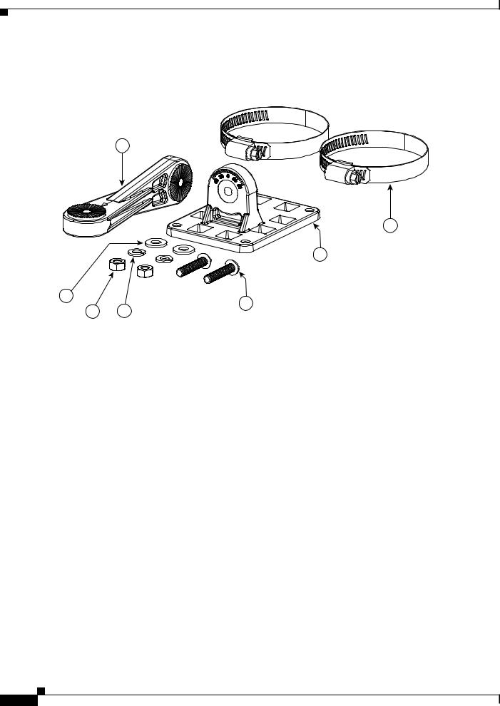
Figure 1 |
Contents of the Antenna Bracket Kit |
2
7 2X
1
2X |
4 |
|
|
3 |
2X |
|
|
6 |
5 |
||
|
2X |
2X |
|
||
|
|
|
|
|
353895
1 |
One of two articulating mount flanges required for the |
5 |
1/4-inch split-lock washers. Two are included in the kit. |
|
installation. The other flange comes attached to the back |
|
|
|
of the antenna. |
|
|
|
|
|
|
2 |
Articulating mount arm. |
6 |
1/4-20 Hex nuts. Two are included in the kit. |
|
|
|
|
3 |
1/4 20 x 1.25-inch stainless steel screws. Two are |
7 |
one of two worm-gear type hose clamps. Each has a range |
|
included in the kit. |
|
of 50–135mm |
|
|
|
|
4 |
1/4 inch flat washers. Two are included in the kit. |
|
|
|
|
|
|
Cisco Aironet 2.4 GHz and 5 GHz Dual-Band Polarization-Diverse Directional Array Antenna (AIR-ANT2566D4M-R)
6
Dimensions of the Antenna and Brackets
Dimensions of the Antenna and Brackets
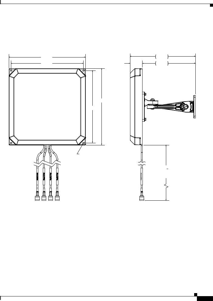
The dimensions noted in the following illustrations are all in mm, unless noted otherwise.
Figure 2 |
Dimensions of the Antenna with Brackets and Cables |
|
|
|
254.0 |
|
217.0 |
|
240.0 |
41.0 |
176.0 |
254.0
240.0
4X  4.50 THRU ALL
36"  1" FROM BOTTOM EDGE OF RADOME
353893
Cisco Aironet 2.4 GHz and 5 GHz Dual-Band Polarization-Diverse Directional Array Antenna (AIR-ANT2566D4M-R)
7
Loading...