


 Loading...
Cisco Systems WAE-7326-K9, WAE-7371-K9, WAE-511-K9, WAE-512-K9, FE-511-K9 User Manual
...Installing the Cisco WAE Inline Network Adapter
Product Number: WAE-INLN-4CG=
Models: FE-511-K9, WAE-511-K9, WAE-611-K9, WAE-512-K9, WAE-612-K9, WAE-7326-K9, WAE-7341-K9,
WAE-7371-K9, WAE-674-K9
This document describes how to install the Cisco WAE inline network adapter in your edge or core WAE appliance. These instructions are intended for experienced technicians.
Note The Cisco WAE inline network adapter is not supported in a Central Manager appliance. (For more information, see the “Important Operational Notes” section on page 7.)
Contents
This document contains the following sections:
•Product Overview
•Safety Guidelines
•Important Operational Notes
•Installing Adapters in the FE-511, WAE-511, and WAE-611 Appliances
•Installing Adapters in the WAE-512 and WAE-612 Appliances
•Installing Adapters in the WAE-7326 Appliance
•Installing Adapters in the WAE-7371, WAE-7341, and WAE-674 Appliances
•Cabling
•Related Documentation
•Obtaining Documentation, Obtaining Support, and Security Guidelines
Americas Headquarters:
Cisco Systems, Inc., 170 West Tasman Drive, San Jose, CA 95134-1706 USA
© 2007–2008 Cisco Systems, Inc. All rights reserved.
Product Overview
Warning IMPORTANT SAFETY INSTRUCTIONS
This warning symbol means danger. You are in a situation that could cause bodily injury. Before you work on any equipment, be aware of the hazards involved with electrical circuitry and be familiar with standard practices for preventing accidents. Use the statement number provided at the end of each warning to locate its translation in the translated safety warnings that accompanied this device.
Statement 1071
SAVE THESE INSTRUCTIONS
Product Overview
This section contains the following topics:
•Inline Network Adapter Description
•Ports and LED Indicators
•Adapter Specifications
Note The minimum software release required for the inline network adapter is WAAS 4.0.7.
Inline Network Adapter Description
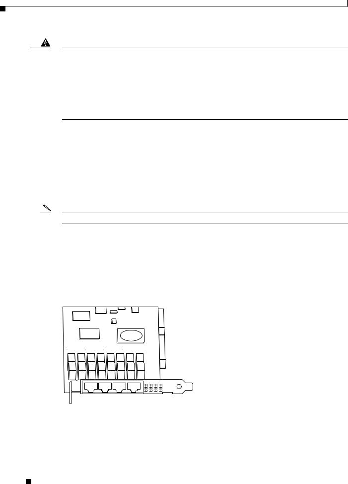
The WAE appliance supports one optional 4-port Ethernet inline network adapter. The inline network adapter is a full-height, three-quarter-length PCI-X network interface card that contains four independent Gigabit Ethernet ports. (See Figure 1.)
Figure 1 |
|
Inline Network Adapter |
|||||||
|
|
|
|
|
|
|
|
|
|
|
|
|
|
|
|
|
|
|
|
|
|
|
|
|
|
|
|
|
|
|
|
|
|
|
|
|
|
|
|
|
|
|
|
|
|
|
|
|
|
|
|
|
|
|
|
|
|
|
|
159701
The Cisco WAE inline network adapter provides an inline traffic interception capability for your appliance. When you configure the WAE appliance for inline interception mode, you can set attributes to control which interfaces are to be used over which VLANs. By default, the adapter operates on all inline-capable interfaces and VLANs. You can configure the inline redirection feature using the WAAS 4.0.7 CLI or the WAAS 4.0.7 Central Manager GUI.
Installing the Cisco WAE Inline Network Adapter
2 |
OL-12480-03 |
|
|
Product Overview
The WAAS software defines two new interface types: A group interface that represents an inline pair grouping and a port interface that represents the individual port. These interfaces are referred to as inlineGroup and inlinePort.
InlineGroup interfaces are numbered using the format slot/group. The slot number is the slot in which the adapter is inserted. (In the WAE 500 series and 600 series appliances, you must install the adapter in slot 1 only.) The group number is either 0 or 1 (each adapter has 2 group pairs). The group number is displayed on the adapter label.
InlinePort interfaces are numbered slot/group/lan or slot/group/wan. The last attribute is the LAN or WAN designator.
The inline network adapter also includes an onboard programmable watch dog timer (WDT) controller that allows you to set the time to wait after a failure event, such as a power outage or a kernel crash, before the unit begins to operate in mechanical bypass mode. In mechanical bypass mode, traffic is bridged between the LAN and WAN ports of each group. Mechanical bypass mode prevents the WAE from becoming a single point of failure and allows traffic to continue to flow between the router and the client while it passes through an unresponsive WAE without being processed.
For more information about configuring the inline network adapter, see the Cisco Wide Area Application Services Configuration Guide.
Ports and LED Indicators
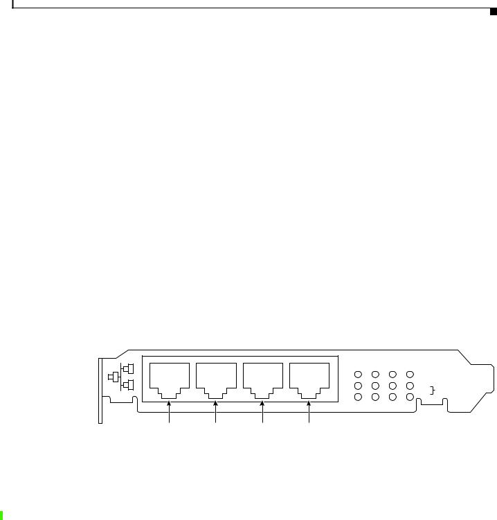
Figure 2 shows the inline network adapter port numbers, interface designations, and LEDs.
Figure 2 |
Inline Network Adapter Port Numbering and LEDs |
W1 L1 W0 L0
LINK/ACT
100
BYPASS
1000
W1 |
L1 |
W0 |
L0 |
272072
|
W1 |
Port WAN1; Group 1 WAN interface |
L1 |
Port LAN1; Group 1 LAN interface |
|
||||
|
|
|
|
|
|
W0 |
Port WAN0; Group 0 WAN interface |
L0 |
Port LAN0: Group 0 LAN interface |
|
||||
|
|
|
|
|
The inline network adapter has three LEDs that correspond to each port (the W1 LEDs correspond to Port W1, and so forth). Table 1 describes the LEDs.
Table 1 Inline Network Adapter LEDs
|
|
LEDs |
State |
Description |
|||
|
|
|
|
|
|||
|
|
Link / Activity |
On |
The 10/100/1000BASE-T interface is receiving power. |
|||
|
|
|
|
|
|||
|
|
|
Blinking |
The Ethernet link is transmitting data. |
|||
|
|
|
|
||||
100 |
On |
The speed of the Ethernet connection is 100BASE-TX. |
|||||
|
|
|
|
|
|
|
|
|
|
|
|
Installing the Cisco WAE Inline Network Adapter |
|
|
|
|
|
|
|
|
|||
|
|
|
|
|
|
|
|
|
OL-12480-03 |
|
|
|
3 |
|
|
|
|
|
|
|
|||

Product Overview
Table 1 |
Inline Network Adapter LEDs (continued) |
||
|
|
|
|
LEDs |
|
State |
Description |
|
|
|
|
1000 |
|
On |
The speed of the Ethernet connection is 1000BASE-TX. |
|
|
|
|
Bypass |
|
Both the 100 and |
The corresponding ports are in mechanical bypass mode. |
|
|
1000 LEDs are on |
|
|
|
|
|
Note On older inline network adapters, the LEDs are labelled 0, 1, 2, and 3. These correspond to W1, L1, W0, and L0 respectively.
Adapter Specifications
Table 2 describes the inline network adapter technical and general specifications.
Table 2 Inline Network Adapter Specifications
|
|
|
|
Specification |
Description |
|
|
|
|
|
|
|
|
|
|
|
|
Copper Gigabit Ethernet Specifications |
|
|
|
|
|
|
|
|
|
|
|
|
|
IEEE standard |
Gigabit Ethernet, 1000BASE-T |
|
|
|
|
|
|
Fast Ethernet, 100BASE-T |
|
|
|
|
|
|
Ethernet, 10BASE-T |
|
|
|
|
|
|
|
|
|
|
|
|
Full duplex and half duplex |
Supports both half-duplex and full-duplex operation in all |
|
|
|
|
|
|
operating speeds |
|
|
|
|
|
|
|
|
|
|
|
|
Autonegotiation |
Autonegotiates between full-duplex and half-duplex operations |
|
|
|
|
|
|
and between 1000-Mbps, 100-Mbps, and 10-Mbps speeds |
|
|
|
|
|
|
|
|
|
|
|
|
Data transfer rate |
1000-Mbps, 100-Mbps, and 10-Mbps speeds per port in |
|
|
|
|
|
|
half-duplex mode |
|
|
|
|
|
|
2000-Mbps, 200-Mbps, and 20-Mbps speeds per port in |
|
|
|
|
|
|
full-duplex mode |
|
|
|
|
|
|
|
|
|
|
|
|
General Technical Specifications |
|
|
|
|
|
|
|
|
|
|
|
|
|
Interface standard |
PCI v2.2 32/64 bit, 33/66 MHz |
|
|
|
|
|
|
PCI-X v1.0 32/64 bit, 66/100/133 MHz |
|
|
|
|
|
|
|
|
|
|
|
|
Size |
6.6 x 4.2 in. (167.64 x 106.68 mm) |
|
|
|
|
|
|
|
|
|
|
|
|
PCI connector |
Universal 64-bit connector |
|
|
|
|
|
|
|
|
|
|
|
|
PCI voltage |
+12 V (minimum 11.4 V, maximum 12.6 V) |
|
|
|
|
|
|
+3.3 V (minimum 3.0 V, maximum 3.6 V) |
|
|
|
|
|
|
|
|
|
|
|
|
Weight |
6.18 oz (175 grams) |
|
|
|
|
|
|
|
|
|
|
|
|
Operating humidity |
0 to 90%, noncondensing |
|
|
|
|
|
|
|
|
|
|
|
|
Operating temperature |
32 to –122oF (0 to 50oC) |
|
|
|
|
|
Storage temperature |
–4 to –149oF (–20 to –65oC) |
|
|
|
|
Installing the Cisco WAE Inline Network Adapter |
|
|
|
|
|
|
|
|
||
|
|
|
|
|
|
|
|
4 |
|
|
|
OL-12480-03 |
|
|
|
|
|
|
||

Safety Guidelines
Safety Guidelines
To reduce the risk of bodily injury, electrical shock, fire, and damage to the equipment, observe the following precautions:
•Warnings
•General Precautions
•Protecting Against Electrostatic Discharge
Warnings
Warning This equipment must be grounded. Never defeat the ground conductor or operate the equipment in the absence of a suitably installed ground conductor. Contact the appropriate electrical inspection authority or an electrician if you are uncertain that suitable grounding is available. Statement 1024
Warning The safety cover is an integral part of the product. Do not operate the unit without the safety cover installed. Operating the unit without the cover in place will invalidate the safety approvals and pose a risk of fire and electrical hazards. Statement 117
Warning Blank faceplates (filler panels) serve three important functions: they prevent exposure to hazardous voltages and currents inside the chassis; they contain electromagnetic interference (EMI) that might disrupt other equipment; and they direct the flow of cooling air through the chassis. Do not operate the system unless all cards and faceplates are in place. Statement 156
Warning Only trained and qualified personnel should be allowed to install, replace, or service this equipment.
Statement 1030
Warning This unit is intended for installation in restricted access areas. A restricted access area can be accessed only through the use of a special tool, lock and key, or other means of security.
Statement 1017
Installing the Cisco WAE Inline Network Adapter
|
OL-12480-03 |
5 |
|
|
|

Safety Guidelines
General Precautions
Observe the following general precautions for using and working with your system:
•Observe and follow service markings. Do not service any Cisco product except as explained in your system documentation. Opening or removing covers that are marked with the triangular symbol with a lightning bolt may expose you to electrical shock. Components inside these compartments should be serviced only by an authorized service technician.
•If any of the following conditions occur, unplug the product from the electrical outlet and replace the part or contact your authorized service provider:
–The power cable or plug is damaged.
–An object has fallen into the product.
–The product has been exposed to water.
–The product has been dropped or damaged.
–The product does not operate correctly when you follow the operating instructions.
•Keep your system components away from radiators and heat sources. Also, do not block cooling vents.
•Do not spill food or liquids on your system components, and never operate the product in a wet environment.
•Do not push any objects into the openings of your system components. Doing so can cause fire or electric shock by shorting out interior components.
•Use the product only with other Cisco-approved equipment.
•Allow the product to cool before removing covers or touching internal components.
•Use the correct external power source. Operate the product only from the type of power source indicated on the electrical ratings label. If you are not sure of the type of power source required, consult your service representative or local power company.
•Use only approved power cables. If you have not been provided with a power cable for your Content Engine or for any AC-powered option intended for your system, purchase a power cable that is approved for use in your country. The power cable must be rated for the product and for the voltage and current marked on the product’s electrical ratings label. The voltage and current rating of the cable should be greater than the ratings marked on the product.
•To help prevent electric shock, plug the system components and peripheral power cables into properly grounded electrical outlets. These cables are equipped with three-prong plugs to help ensure proper grounding. Do not use adapter plugs or remove the grounding prong from a cable.
•Do not use appliance or voltage converters or kits sold for appliances with your product.
•To help protect your system components from sudden, transient increases and decreases in electrical power, use a surge suppressor or line conditioner.
•Position cables and power cords carefully; route cables and the power cord and plug so that they cannot be stepped on or tripped over. Be sure that nothing rests on your system components’ cables or power cord.
•Do not modify power cables or plugs. Consult a licensed electrician or your power company for site modifications. Always follow your local or national wiring rules.
Installing the Cisco WAE Inline Network Adapter
6 |
OL-12480-03 |
|
|

Important Operational Notes
Protecting Against Electrostatic Discharge
Static electricity can harm delicate components inside your system. To prevent static damage, discharge static electricity from your body before you touch any of your system’s electronic components. You can do so by touching an unpainted metal surface on the chassis.
You can also take the following steps to prevent damage from electrostatic discharge (ESD):
•Limit your movement. Movement can cause static electricity to build up around you.
•When transporting a sensitive component, first place it in an antistatic container or packaging.
•Just before unwrapping the antistatic packaging, be sure to discharge static electricity from your body by touching it to an unpainted metal part of the system unit for at least 2 seconds.
•Remove the adapter from its packaging and install it directly into your system unit without setting it down. If it is necessary to set the adapter down, place it in its static-protective package. Do not place the adapter on your system unit cover or on a metal table.
•Handle all sensitive components in a static-safe area. If possible, use antistatic floor pads and workbench pads.
•Handle the adapter carefully, holding it by its edges or its frame.
•Do not touch solder joints, pins, or exposed printed circuitry.
•Do not leave the adapter where others can handle and possibly damage the adapter.
•Take additional care when handling adapters during cold weather because heating reduces indoor humidity and increases static electricity.
Important Operational Notes
If you intend to reconfigure an edge or core WAE with a Cisco WAE inline network adapter installed in it as a Central Manager device, first remove the inline network adapter. The inline network adapter is not supported in a Central Manager appliance.
Installing Adapters in the FE-511, WAE-511, and WAE-611
Appliances
This section describes how to install the inline network adapter in the FE-511, WAE-511, and the WAE-611 appliances. This section includes the following procedures:
•Removing the Cover
•Installing an Inline Network Adapter
•Completing the Installation
Installing the Cisco WAE Inline Network Adapter
|
OL-12480-03 |
7 |
|
|
|
Installing Adapters in the FE-511, WAE-511, and WAE-611 Appliances
Removing the Cover
|
|
|
|
|
Warning |
Before working on a system that has an on/off switch, turn OFF the power and unplug the power cord. |
|||
|
|
|
Statement 1 |
|
|
|
|
|
|
|
|
|
To remove the cover, follow these steps: |
|
|
|
|
||
Step 1 |
Review the information in the “Safety Guidelines” section on page 5. |
|||
Step 2 |
Power down the appliance and all attached devices. Disconnect the power cord and all external cables. |
|||
Step 3 |
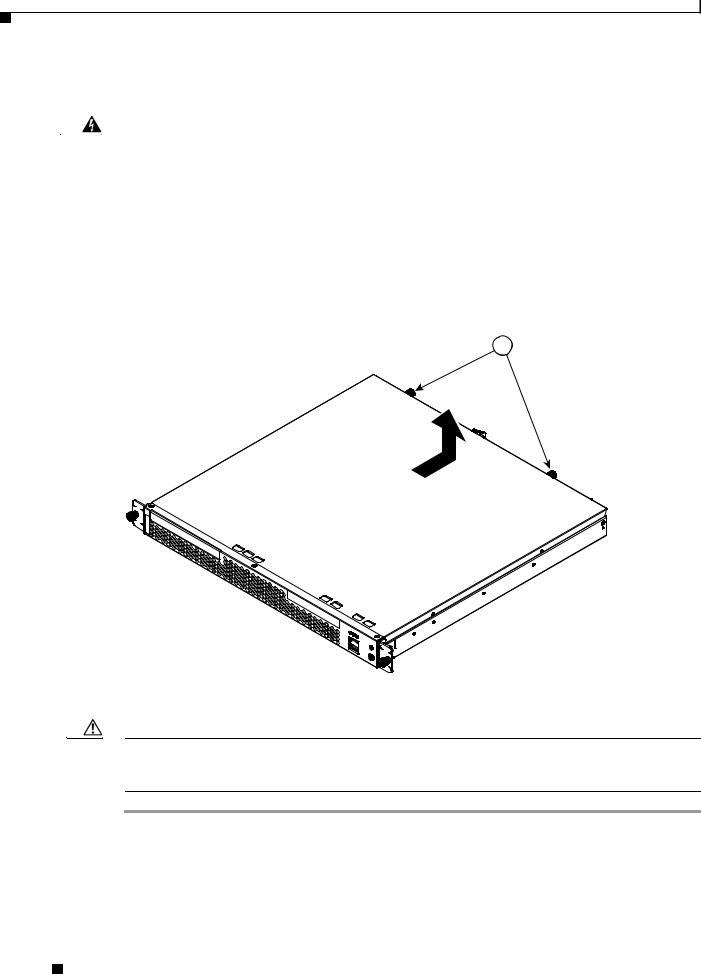
Loosen the two captive screws (labeled 1 in Figure 3) on the rear of the cover. |
|||
|
|
|
Figure 3 |
Removing the Cover |
|
|
|
|
1 |
115802
Step 4 Slide the cover back, and then lift it up and off the appliance.
Caution For proper cooling and airflow, replace the cover before turning on the appliance. Operating the appliance for extended periods (over 30 minutes) with the cover removed might damage appliance components.
Installing the Cisco WAE Inline Network Adapter
8 |
OL-12480-03 |
|
|

Installing Adapters in the FE-511, WAE-511, and WAE-611 Appliances
Installing an Inline Network Adapter
Before you install an adapter, review the following information:
•The adapter slots are on the riser card assembly. You must first remove the riser card assembly to access the adapter slots. (See Figure 4.)
•The appliance has two Peripheral Component Interconnect-Extended (PCI-X) adapter slots:
–PCI-X slot 1 is for one full-height three-quarter-length adapter.
–PCI-X slot 2 is for one low-profile half-length adapter; however, it is not used in this appliance.
•You must install the inline network adapter in PCI-X slot 1. (This slot is labeled “PCI 1” on the back of the appliance.)
Caution When you handle static-sensitive adapters and appliances, take precautions to avoid damage from static electricity. For details on handling these devices, see the “Protecting Against Electrostatic Discharge” section on page 7.
Note The illustrations in this document might differ slightly from your hardware.
To install an inline network adapter, follow these steps:
Step 1 Review the safety information in the “Safety Guidelines” section on page 5.
Step 2 Power down the appliance and peripheral devices.
Step 3 Disconnect the power cord and then all external cables from the appliance.
Step 4 Remove the appliance cover.
Note You may find it easier to route the cables before you install the adapter.
Step 5 Loosen the captive screw (labeled 3 in Figure 4) located on the rear of the appliance adjacent to PCI-X slot 1 and remove the expansion slot cover.
Note You must install PCI expansion slot covers on all vacant slots so that you can maintain the electronic emissions characteristics of the appliance and ensure proper cooling of internal components.
Installing the Cisco WAE Inline Network Adapter
|
OL-12480-03 |
9 |
|
|
|

Installing Adapters in the FE-511, WAE-511, and WAE-611 Appliances
Figure 4 |
Removing the Expansion Slot Cover |
|
|
|
124478 |
|
1 |
|
|
|
2 |
4 |
|
|
|
3 |
|
1 |
Expansion slot cover (slot 2) |
2 |
Expansion slot cover (slot 1) |
3 |
Captive screw |
4 |
Riser card assembly |
Step 6 Remove the riser card (labeled 1 in Figure 5) from the system board to access the expansion slot.
Installing the Cisco WAE Inline Network Adapter
10 |
OL-12480-03 |
|
|
Loading...