


 Loading...
USER GUIDE
24-Port 10/100 + |
BUSINESS SERIES |
2 Port Gigabit Switch + |
|
2 MiniGBIC |
|
|
|
Model: SR224G

Table of Contents
Chapter 1: Introduction |
1 |
The 24-Port 10/100 + 2-Port Gigabit Switch + 2 MiniGBIC |
1 |
Features |
2 |
Chapter 2: Product Overview |
3 |
Front Panel |
3 |
Back Panel |
4 |
Side Panel |
4 |
Placement Options |
4 |
Chapter 3: Installation |
6 |
Overview |
6 |
Connection Instructions |
7 |
Appendix A: Specifications |
8 |
Appendix B: Warranty and Regulatory Information |
9 |
Limited Warranty |
9 |
FCC Statement |
11 |
Safety Notices |
11 |
Industry Canada Statement |
12 |
Règlement d’Industry Canada |
12 |
EC Declaration of Conformity (Europe) |
12 |
User Information for Consumer Products Covered by EU Directive |
|
2002/96/EC on Waste Electric and Electronic Equipment (WEEE) |
13 |
Appendix C: Contact Information |
21 |
24-Port 10/100 + 2-Port Gigabit Switch + 2 MiniGBIC |
|
About This User Guide
About This User Guide
Icon Descriptions
While reading through the User Guide, you may encounter various icons designed to call attention to a specific item. Below are descriptions of these icons:
NOTE: This check mark indicates that there is a note of interest and is something that you should pay special attention to while using the product.
WARNING: This exclamation point indicates that there is a caution or warning and it is something that could damage your property or product.
WEB: This globe icon indicates a noteworthy website address or e-mail address.
Online Resources
Most web browsers allow you to enter the web address without adding the http:// in front of the address. This User Guide will refer to websites without including http:// in front of the address. Some older web browsers may require you to add it.
Resource |
Website |
Linksys |
www.linksys.com |
Linksys International |
www.linksys.com/international |
Glossary |
www.linksys.com/glossary |
|
|
Network Security |
www.linksys.com/security |
|
|
Copyright and Trademarks
Specifications are subject to change without notice. Linksys is a registered trademark or trademark of Cisco Systems, Inc. and/or its affiliates in the U.S. and certain other countries. Copyright © 2007 Cisco Systems, Inc. All rights reserved. Other brands and product names are trademarks or registered trademarks of their respective holders.
ii |
24-Port 10/100 + 2-Port Gigabit Switch + 2 MiniGBIC |

Chapter 1: Introduction
Chapter 1:
Introduction
The 24-Port 10/100 + 2-Port Gigabit Switch + 2
MiniGBIC
This new Linksys rack-mount switch delivers non-blocking, wire speed switching for your 10/100 Mbps network clients, plus multiple options for connecting to your network backbone. Twenty-four 10/100 ports wire-up your workstations, while the integrated 10/100/1000 ports or miniGBIC ports connect to your servers or backbone at Gigabit speeds.
The SR224G incorporates non-blocking, wire-speed architecture that forwards packets as fast as your network can deliver them. It features broadcast storm suppression that maximizes the system availability. Also included are Address Learning and Aging function to prevent data transfer errors and Data Flow Control to help prevent packet loss.
All ports have automatic MDI/MDI-X crossover detection, so you don’t have to worry about the cable type. Each port independently and automatically negotiates for best speed and whether to run in halfor full-duplex mode. Head-of-line blocking prevention keeps your highspeed clients from bogging down in lower-speed traffic and fast store- and-forward switching prevents damaged packets from being passed on into the network.
No matter how intensive your network demands, the Linksys 24-Port 10/100 + 2-Port Gigabit Switch + 2 MiniGBIC has speed, flexibility, and reliability that you can count on.
24-Port 10/100 + 2-Port Gigabit Switch + 2 MiniGBIC

Chapter 1: Introduction
Features
•Ideal for integrating your 10 Mbps and 100 Mbps network hardware
•24 10/100 Ports provide dedicated bandwidth in Half or Full-Duplex modes
•2 Gigabit Ethernet ports and 2 shared miniGBIC slots for Gigabit Fiber expansion
•Each port supports Auto MDI/MDI-X cable detection
•Compatible with all major network operating systems
•Advanced store-and-forward packet switching optimizes data transfers
•Auto partitioning protects PCs from downed network lines
•Signal regeneration ensures data transfer integrity
24-Port 10/100 + 2-Port Gigabit Switch + 2 MiniGBIC
Chapter 2: Product Overview
Chapter 2:
Product Overview
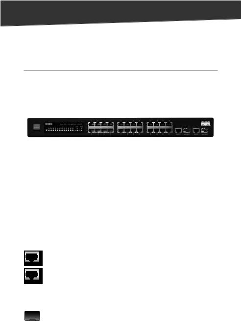
Front Panel
The LEDs and network ports are located on the front panel of the Switch.
Front Panel
LEDs
System (Green) This LED lights up and remains lit when the Switch is powered on.
1-24 (Green) Each LED lights up when a connection is made through its corresponding port. It flashes when the corresponding port is active.
Gigabit/miniGBIC 1-2 (Green) The Gigabit/miniGBIC LED lights up when a connection is made through the corresponding Gigabit port. It flashes when the corresponding port is active.
Ports
1-24 These ports connect the Switch to network devices, such as computers.
Gigabit 1-2 The Gigabit RJ-45 ports support 10/100/1000 Mbps connections and are connection points for network devices such as Gigabit servers. Each Gigabit RJ 45 port is paired with a miniGBIC port. If a miniGBIC module is present, the corresponding 10/100/1000 RJ-45 port will be disabled.
MiniGBIC 1-2 The two miniGBIC (Gigabit interface converter) ports are connection points for miniGBIC modules, so the Switch can uplink via fiber to another switch or two. The miniGBIC ports are compatible with the MGBSX1, MGBLH1, and MGBT1 only.
24-Port 10/100 + 2-Port Gigabit Switch + 2 MiniGBIC |
|
Chapter 2: Product Overview
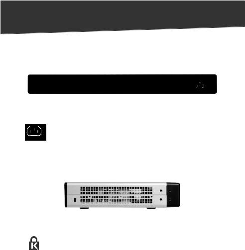
Back Panel
The power port is located on the back panel of the Switch.
Back Panel
Power The power port is where you will connect the included power cord.
Side Panel
The security slot is located on the side panel of the Switch.
Side Panel with Security Slot
Security slot The security slot is where you can attach a lock to protect the Switch from theft.
Placement Options
There are two ways to physically install the Switch:
•Set the Switch on its four rubber feet.
•Mount the Switch in a standard rack (1U high).
24-Port 10/100 + 2-Port Gigabit Switch + 2 MiniGBIC

Chapter 2: Product Overview
Rack-Mount
To rack-mount the Switch, follow these instructions:
1The Switch has four mounting holes on each side. Screw an included mounting bracket into each side.
Attach the Brackets
2Lift the Switch into the rack, and secure the brackets with additional screws (not included).
Connect to Rack
24-Port 10/100 + 2-Port Gigabit Switch + 2 MiniGBIC |
|
Loading...