


SR216
Quick Start Guide
Cisco Small Business
Models SR216 and SR224
16-Port and 24-Port 10/100 Switches
Package Contents
• SR216 or SR224 Switch
• Power Cord
• Quick Start Guide
Product Overview
Thank you for choosing the 16-Port or 24-Port 10/100 Switch. The 16-Port and
24-Port 10/100 Switches provide non-blocking, wire-speed switching for your
10, and 100 Mbps network clients.
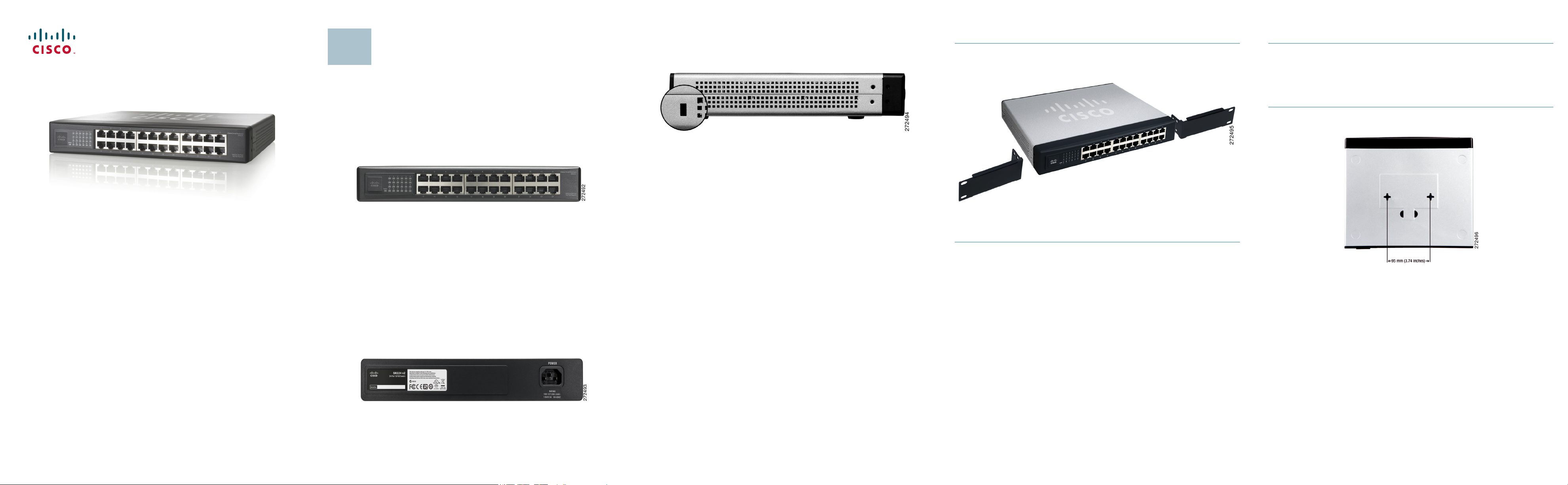
Front Panel
The 16-Port and 24-Port 10/100 Switches differ in number of LEDs and ports.
Pictured here is the 24-Port Switch; however, the 24-Port Switch is similar in
form. The LEDs and ports are located on the front panel of the Switch.
Front Panel of the SR224
System—(Green) This LED lights up and remains lit when the Switch is
powered on.
1-16 (SR216) or 1-24 (SR224)—Each LED lights up when a connection is made
through the corresponding port. It flashes when the corresponding port is
active.
1-16 or 1-24—These ports connect the Switch to network devices, such as
computers.
Back Panel
The power port is located on the back panel of the Switch.The power port is
where you will connect the included power cord.
1
Side Panel
The security slot is located on the side panel of the Switch.
The security slot is where you can attach a lock to protect the Switch from theft.
Placement Options
There are three ways to physically install the Switch:
• Set the Switch on its four rubber feet
• Mount the Switch in a standard-sized rack (1U high)
• Wall-mount the Switch using the wall-mount slots
Rack Mount Instruction Tips
• Ambient Temperature—To prevent the switch from overheating, do not
operate the switch in an area that exceeds the recommended ambient
temperature.
• Reduced Air Flow—If you install the switch in a rack, be sure that there is
adequate air flow as required.
• Mechanical Loading—Be sure that the switch is level and stable when you
mount the switch in a rack to avoid any hazardous condition.
• Circuit Overloading—Do not overload the power outlet or circuit when
installing multiple devices in a rack.
• Reliable Grounding—Be sure that the switch is grounded and use suitable
electrical supply connections.
To rack mount the Switch, follow these instructions:
STEP 1 The Switch has four mounting holes on each side. Screw an
included mounting bracket into each side.
S
TEP 2 Place the Switch in the rack, and secure the brackets with additional
screws (not included).
To wall-mount the Switch, follow these instructions:
STEP 1 The wall-mount slots are two crisscross slots on the Switch’s
bottom panel. The distance between the two slots is 95 mm
(3.74 inches). Attach two screws to the wall, so that the Switch’s
wall-mount slots line up with the two screws.
S
TEP 2 Maneuver the Switch so the screws are inserted into the two slots.
 Loading...