


OL-4266-08
Table of contents
 Loading...
CHA PTER
42-1
Cisco 7600 Series Router Cisco IOS Software Configuration Guide, Release 12.2SX
OL-4266-08
42
Configuring PFC QoS
This chapter describes how to configure quality of service (QoS) as implemented on the Policy Feature
Card (PFC) and Distributed Forwarding Cards (DFCs) on the Cisco 7600 series routers.
Note • For complete syntax and usage information for the commands used in this chapter, refer to the
Cisco 7600 Series Router Cisco IOS Command Reference at this URL:
http://www.cisco.com/univercd/cc/td/doc/product/core/cis7600/software/122sx/cmdref/index.htm
• For information about QoS and MPLS, see Chapter 43, “Configuring PFC3BXL or PFC3B Mode
MPLS QoS.”
• QoS on the Cisco 7600 series routers (PFC QoS) uses some Cisco IOS modular QoS CLI (MQC).
Because PFC QoS is implemented in hardware, it supports only a subset of the MQC syntax.
• The PFC3 does not support Network-Based Application Recognition (NBAR).
• With a Supervisor Engine 2, PFC2, and MSFC2, you can configure NBAR on Layer 3 interfaces
instead of PFC QoS:
–
The PFC2 provides hardware support for input ACLs on ports where you configure NBAR.
–
When PFC QoS is enabled, the traffic through ports where you configure NBAR passes through
the ingress and egress queues and drop thresholds.
–
When PFC QoS is enabled, the MSFC2 sets egress CoS equal to egress IP precedence in NBAR
traffic.
–
After passing through an ingress queue, all traffic is processed in software on the MSFC2 on
interfaces where you configure NBAR.
–
To configure NBAR, refer to this publication:
http://www.cisco.com/univercd/cc/td/doc/product/software/ios122/122newft/122t/122t8/dtnba
rad.htm
This chapter contains these sections:
• Understanding How PFC QoS Works, page 42-2
• PFC QoS Default Configuration, page 42-28
• PFC QoS Configuration Guidelines and Restrictions, page 42-49
• Configuring PFC QoS, page 42-55
• Common QoS Scenarios, page 42-112
• PFC QoS Glossary, page 42-122

42-2
Cisco 7600 Series Router Cisco IOS Software Configuration Guide, Release 12.2SX
OL-4266-08
Chapter 42 Configuring PFC QoS
Understanding How PFC QoS Works
Understanding How PFC QoS Works
The term “PFC QoS” refers to QoS on the Cisco 7600 series router. PFC QoS is implemented on various
router components in addition to the PFC and any DFCs. These sections describe how PFC QoS works:
• Port Types Supported by PFC QoS, page 42-2
• Overview, page 42-2
• Component Overview, page 42-6
• Understanding Classification and Marking, page 42-16
• Understanding Port-Based Queue Types, page 42-22
Port Types Supported by PFC QoS
The PFC does not provide QoS for FlexWAN module ports. Refer to this publication for information
about FlexWAN module QoS features:
http://www.cisco.com/univercd/cc/td/doc/product/core/cis7600/cfgnotes/flexport/combo/index.htm
In all releases, PFC QoS supports LAN ports. LAN ports are Ethernet ports on Ethernet switching
modules, except for the 4-port Gigabit Ethernet WAN (GBIC) modules (OSM-4GE-WAN and
OSM-2+4GE-WAN+). Some OSMs have four Ethernet LAN ports in addition to WAN ports.
With Release 12.2(17b)SXA and later releases, PFC QoS supports optical services module (OSM) ports.
OSM ports are the WAN ports on OSMs. Refer to the following publication for information about
additional OSM QoS features:
http://www.cisco.com/univercd/cc/td/doc/product/core/cis7600/cfgnotes/osm_inst/index.htm
Overview
Typically, networks operate on a best-effort delivery basis, which means that all traffic has equal priority
and an equal chance of being delivered in a timely manner. When congestion occurs, all traffic has an
equal chance of being dropped.
QoS makes network performance more predictable and bandwidth utilization more effective. QoS
selects (classifies) network traffic, uses or assigns QoS labels to indicate priority, makes the packets
comply with the configured resource usage limits (polices the traffic and marks the traffic), and provides
congestion avoidance where resource contention exists.
PFC QoS classification, policing, marking, and congestion avoidance is implemented in hardware on the
PFC, DFCs, and in LAN switching module port Application Specific Integrated Circuits (ASICs).
Note Cisco 7600 series routers do not support all of the MQC features (for example, Committed Access Rate
(CAR)) for traffic that is Layer 3 switched or Layer 2 switched in hardware. Because queuing is
implemented in the port ASICs, Cisco 7600 series routers do not support MQC-configured queuing.
Figure 42-1 shows an overview of QoS processing in a Cisco 7600 series router.

42-3
Cisco 7600 Series Router Cisco IOS Software Configuration Guide, Release 12.2SX
OL-4266-08
Chapter 42 Configuring PFC QoS
Understanding How PFC QoS Works
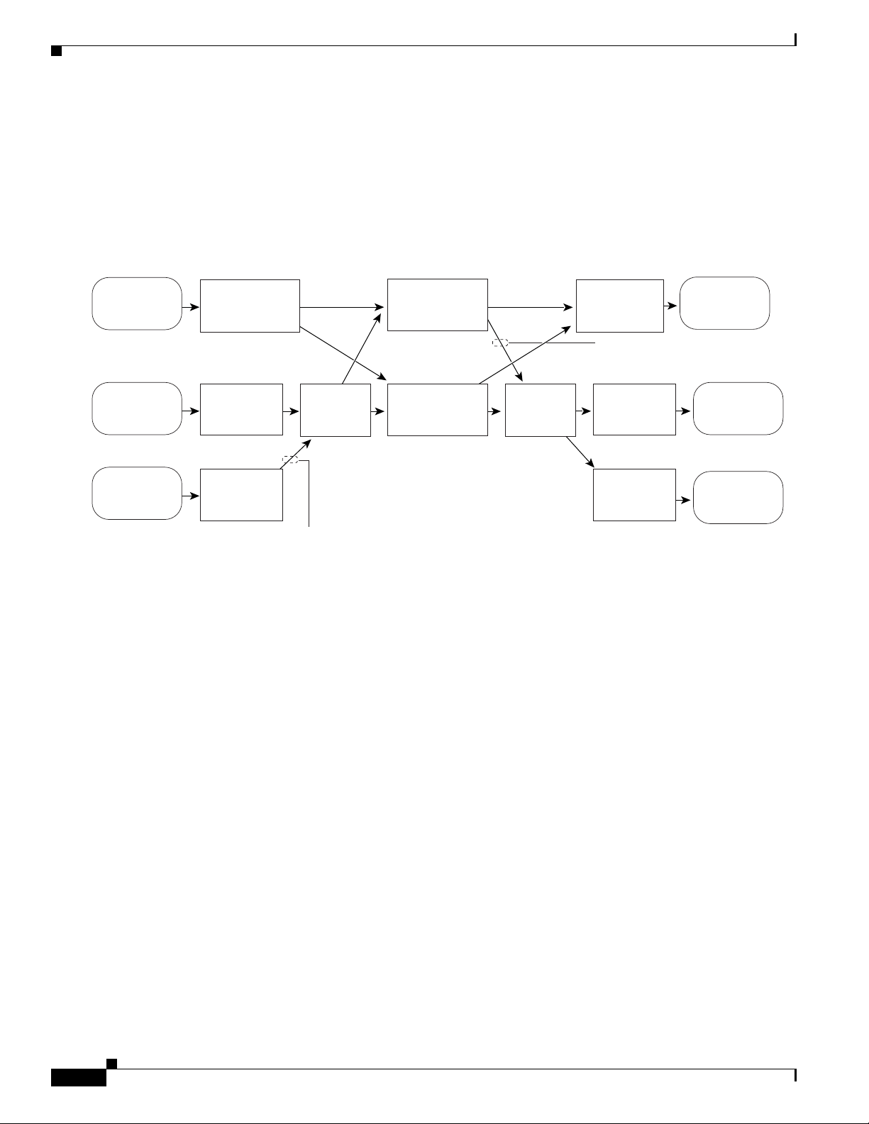
Figure 42-1 PFC QoS Feature Processing Overview
The PFC QoS features are applied in this order:
1. Ingress port PFC QoS features:
–
Port trust state—In PFC QoS, trust means to accept as valid and use as the basis of the initial
internal DSCP value. Ports are untrusted by default, which sets the initial internal DSCP value
to zero. You can configure ports to trust received CoS, IP precedence, or DSCP.
–
Layer 2 CoS remarking—PFC QoS applies Layer 2 CoS remarking, which marks the incoming
frame with the port CoS value, in these situations:
—If the traffic is not in an ISL, 802.1Q, or 802.1p frame.
—If a port is configured as untrusted.
On OSM ATM and POS ports, PFC QoS always sets ingress CoS equal to zero.
–
Congestion avoidance—If you configure an Ethernet LAN port to trust CoS or DSCP, QoS
classifies the traffic on the basis of its Layer 2 CoS value or its Layer 3 DSCP value and assigns
it to an ingress queue to provide congestion avoidance. Layer 3 DSCP-based queue mapping is
available only on WS-X6708-10GE ports.
2. PFC and DFC QoS features:
–
Internal DSCP—On the PFC and DFCs, QoS associates an internal DSCP value with all traffic
to classify it for processing through the system. There is an initial internal DSCP based on the
traffic trust state and a final internal DSCP. The final internal DSCP can be the same as the
initial value or an MQC policy map can set it to a different value.
–
MQC policy maps—MQC policy maps can do one or more of these operations:
—Change the trust state of the traffic (bases the internal DSCP value on a different QoS label)
—Set the initial internal DSCP value (only for traffic from untrusted ports)
—Mark the traffic
—Police the traffic
3. Egress Ethernet LAN port QoS features:
–
Layer 3 DSCP marking with the final internal DSCP (always with PFC2, optionally with PFC3)
–
Layer 2 CoS marking mapped from the final internal DSCP
–
Layer 2 CoS-based and Layer 3 DSCP-based congestion avoidance. (Layer 3 DSCP-based
queue mapping is available only on WS-X6708-10GE ports.)
MSFC
PFC
Switching
Module
1
1
2
2
3
3
Switching
Module
120559
42-4
Cisco 7600 Series Router Cisco IOS Software Configuration Guide, Release 12.2SX
OL-4266-08
Chapter 42 Configuring PFC QoS
Understanding How PFC QoS Works
These figures provide more detail about the relationship between QoS and the router components:
• Figure 42-2, Traffic Flow and PFC QoS Features with PFC3
• Figure 42-3, Traffic Flow and PFC QoS Features with PFC2
• Figure 42-4, PFC QoS Features and Component Overview
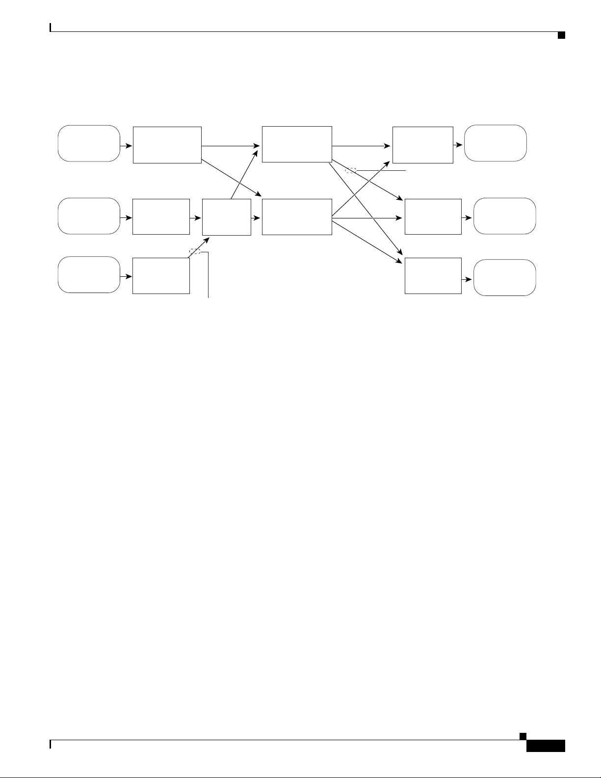
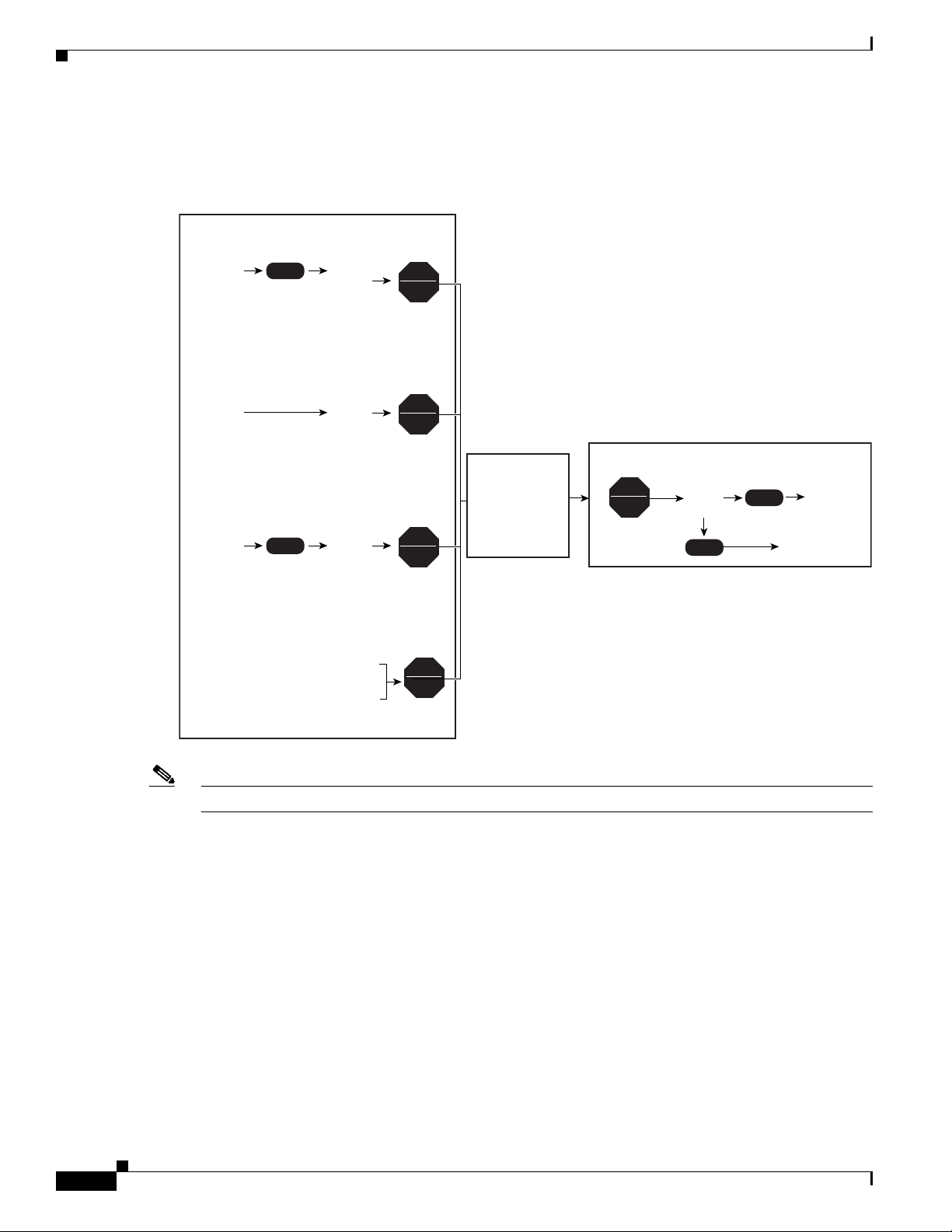
Figure 42-2 shows traffic flow and PFC QoS features with a PFC3.
Figure 42-2 Traffic Flow and PFC QoS Features with PFC3
Figure 42-2 shows how traffic flows through the PFC QoS features with PFC3:
• Traffic can enter on any type of port and exit on any type of port.
• DFCs implement PFC QoS locally on switching modules.
• For FlexWAN module traffic:
–
Ingress FlexWAN QoS features can be applied to FlexWAN ingress traffic.
–
Ingress FlexWAN traffic can be Layer 3-switched by the PFC3 or routed in software by the MSFC.
–
Egress PFC QoS is not applied to FlexWAN ingress traffic.
–
Egress FlexWAN QoS can be applied to FlexWAN egress traffic.
• For LAN-port traffic:
–
Ingress LAN-port QoS features can be applied to LAN-port ingress traffic.
–
Ingress PFC QoS can be applied to LAN-port ingress traffic.
–
Ingress LAN-port traffic can be Layer-2 or Layer-3 switched by the PFC3 or routed in software
by the MSFC.
–
Egress PFC QoS and egress LAN-port QoS can be applied to LAN-port egress traffic.
• For OSM traffic:
–
Ingress OSM-port QoS features can be applied to OSM-port ingress traffic.
–
Ingress PFC3 QoS can be applied to OSM-port ingress traffic.
–
Ingress OSM-port traffic can be Layer-3 switched by the PFC3 or routed in software by the MSFC.
–
Egress PFC3 QoS and egress OSM-port QoS can be applied to OSM-port egress traffic.
Transmit
FlexWAN traffic
Multilayer Switch
Feature Card
(MSFC)
Transmit
OSM traffic
105757
FlexWAN traffic
enters switch
FlexWAN
ingress port and
QoS features
FlexWAN
egress port and
QoS features
OSM traffic
enters switch
OSM ingress
port and
QoS freatures
OSM egress
port and
QoS freatures
CoS = 0 for all ATM and POS traffic (not configurable)
CoS = IP precedence for all traffic
(not configurable)
Transmit
LAN traffic
LAN traffic
enters switch
LAN ingress
port and
QoS features
LAN egress
port and
QoS features
Ingress
PFC3
QoS
Egress
PFC3
QoS
PFC3
Layer 2 or 3
switching
42-5
Cisco 7600 Series Router Cisco IOS Software Configuration Guide, Release 12.2SX
OL-4266-08
Chapter 42 Configuring PFC QoS
Understanding How PFC QoS Works
Figure 42-3 shows traffic flow and PFC QoS features with a PFC2.
Figure 42-3 Traffic Flow and PFC QoS Features with PFC2
Figure 42-3 shows how traffic flows through the PFC QoS features with PFC2:
• Traffic can enter on any type of port and exit on any type of port.
• DFCs implement PFC QoS locally on switching modules.
• For FlexWAN module traffic:
–
Ingress FlexWAN QoS features can be applied to FlexWAN ingress traffic.
–
Ingress FlexWAN traffic can be Layer 3-switched by the PFC2 or routed in software by the
MSFC2.
–
Egress FlexWAN QoS can be applied to FlexWAN egress traffic.
• For LAN-port traffic:
–
Ingress LAN-port QoS features can be applied to LAN-port ingress traffic.
–
Ingress LAN-port traffic can be Layer-2 or Layer-3 switched by the PFC2 or routed in software
by the MSFC2.
–
Egress LAN-port QoS can be applied to LAN-port egress traffic.
• For OSM traffic:
–
OSM-port QoS features can be applied to OSM-port ingress traffic.
–
Ingress PFC2 QoS can be applied to OSM-port ingress traffic.
–
OSM-port ingress traffic can be Layer-3 switched by the PFC2 or routed in software by the
MSFC2.
–
Egress OSM-port QoS can be applied to OSM-port egress traffic.
Transmit
FlexWAN traffic
Multilayer Switch
Feature Card 2
(MSFC2)
Transmit
OSM traffic
120185
FlexWAN traffic
enters switch
FlexWAN
ingress port and
QoS features
FlexWAN
egress port and
QoS features
OSM traffic
enters switch
OSM ingress
port and
QoS freatures
OSM egress
port and
QoS freatures
CoS = 0 for all ATM and POS traffic (not configurable)
CoS = IP precedence for all traffic
(not configurable)
Transmit
LAN traffic
LAN traffic
enters switch
LAN ingress
port and
QoS features
LAN egress
port and
QoS features
Ingress
PFC2
QoS
PFC2
Layer 2 or 3
switching
42-6
Cisco 7600 Series Router Cisco IOS Software Configuration Guide, Release 12.2SX
OL-4266-08
Chapter 42 Configuring PFC QoS
Understanding How PFC QoS Works
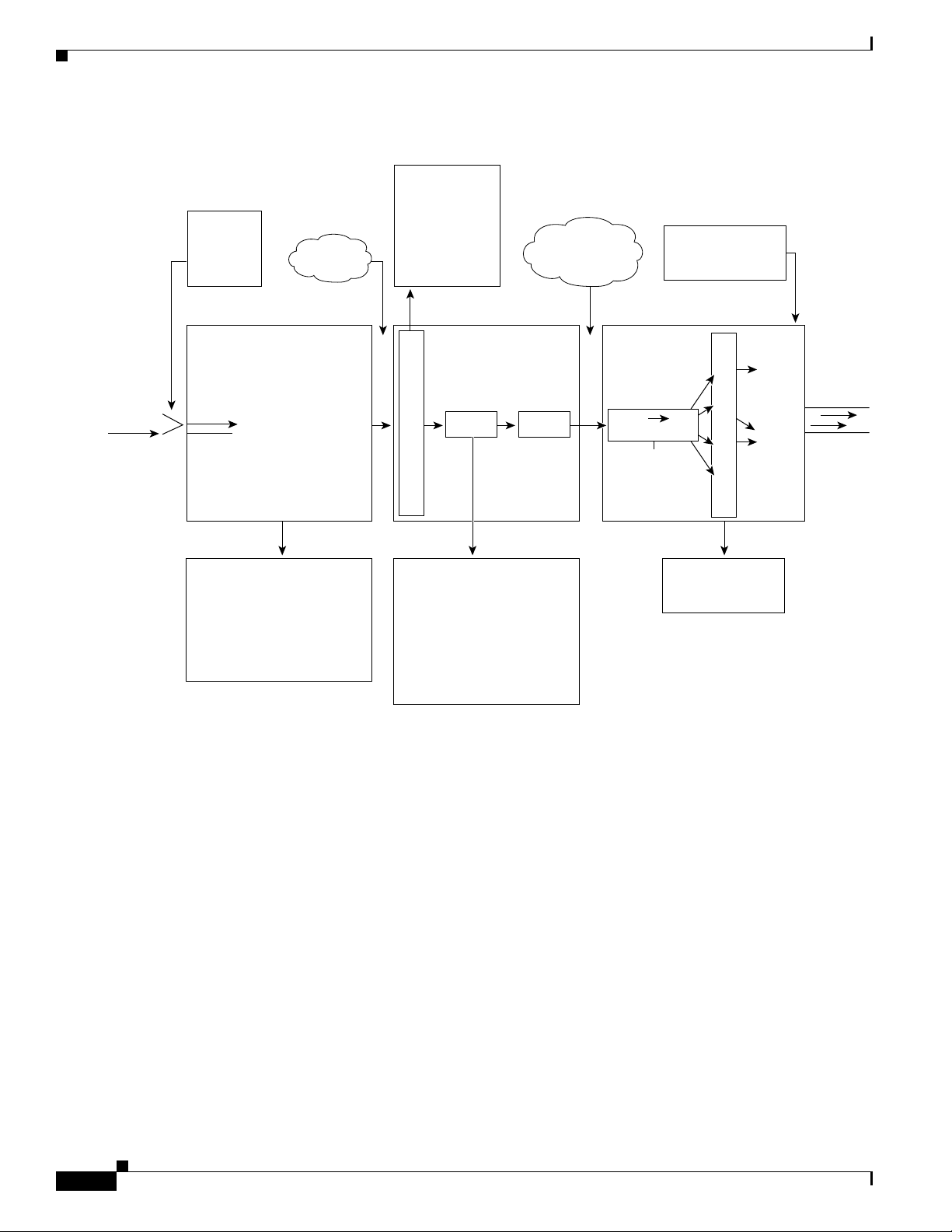
Figure 42-4 PFC QoS Features and Component Overview
Component Overview
These sections provide more detail about the role of the following components in PFC QoS decisions
and processes:
• Ingress LAN Port PFC QoS Features, page 42-6
• PFC and DFC QoS Features, page 42-8
• PFC QoS Egress Port Features, page 42-12
Ingress LAN Port PFC QoS Features
These sections provide an overview of the ingress port QoS features:
• Flowchart of Ingress LAN Port PFC QoS Features, page 42-7
• Port Trust, page 42-8
• Ingress Congestion Avoidance, page 42-8
Por t Trus t
- CoS
- IP Prec
- DSCP
- MPLS Exp
DSCP
map
Final internal
DSCP is
mapped to CoS
Identify traffic
based on match
criteria:
- ACL (L2, IP)
- DSCP
- IP Prec
- MPLS Exp
- Class-map
Scheduler operates
on WRR, DWRR,
SP
Ingress Port
Egress PortPFC/DFC
Policy Result
SP
DSCP CoS
rewrite
C
l
a
s
s
i
f
i
c
a
t
i
o
n
CoS determies
queue selection
Scheduler queue
and threshold are
configurable
Q1
Q2
Q3
Q4
WRR
DWRR
Outgoing
CoS set on
trunk port
DSCP set
for IP
Action - policy map
Trust - DSCP, IP Prec
MPLS Exp
Mark - set internal
DSCP
Police - rate limit; mark; drop
Scheduling rules: WRR, PQ
Queueing based on CoS
Scheduler
Q1
Q2
To S
CoS
Incoming
137031
42-7
Cisco 7600 Series Router Cisco IOS Software Configuration Guide, Release 12.2SX
OL-4266-08
Chapter 42 Configuring PFC QoS
Understanding How PFC QoS Works
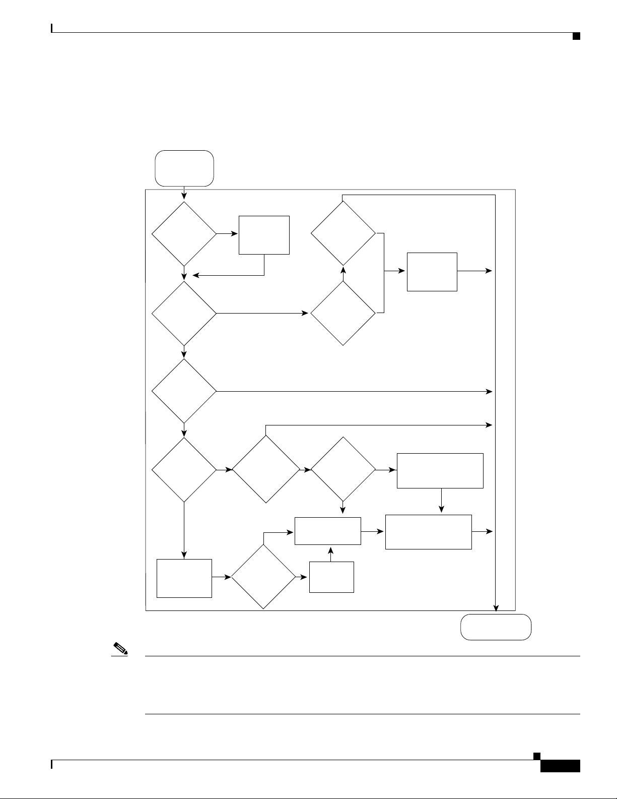
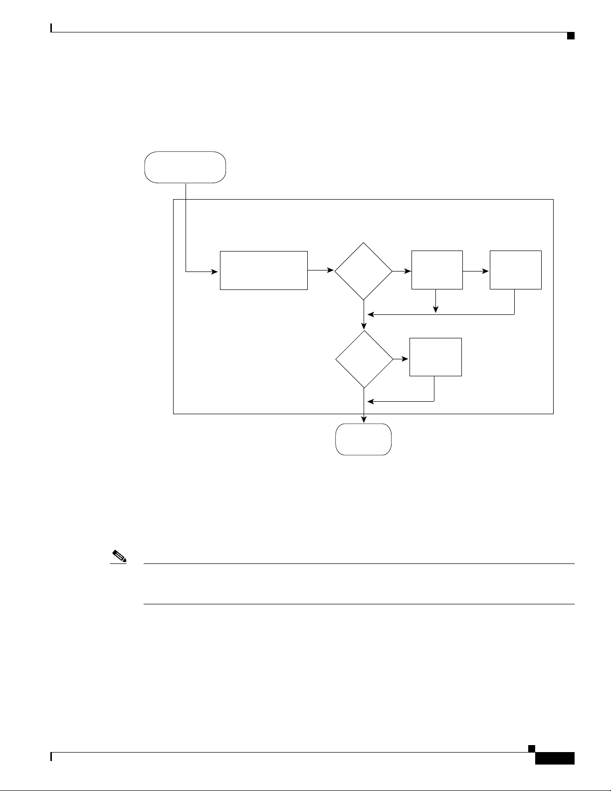
Flowchart of Ingress LAN Port PFC QoS Features
Figure 42-5 shows how traffic flows through the ingress LAN port PFC QoS features.
Figure 42-5 Ingress LAN Port PFC QoS Features
Note • Ingress CoS mutation is supported only on 802.1Q tunnel ports.
• Release 12.2(18)SXF5 and later releases support the ignore port trust feature.
• DSCP-based queue mapping is supported only on WS-X6708-10GE ports.
154684
Ye s
Frame
enters
switch
Port set to
untrusted?
ISL or
802.1Q?
No
No
No
Port set to
trust-ipprec?
Port set to
trust-dscp?
Ingress
CoS
Mutation?
IP
traffic with
recognizable
ToS byte?
IP
traffic with
recognizable
ToS byte?
Ignore
port trust
enabled?
DSCP-based
queue mapping
enabled?
No
No
No
No
No
No
Port is set to
trust-cos
To
PFC
Apply
port
CoS
Apply
port
CoS
Ye s Ye s Ye s
Ye s
Ye s
Mutate
CoS
Ingress queues and
drop thresholds
DSCP-to-queue
map
CoS-to-queue
map
Yes
Yes

42-8
Cisco 7600 Series Router Cisco IOS Software Configuration Guide, Release 12.2SX
OL-4266-08
Chapter 42 Configuring PFC QoS
Understanding How PFC QoS Works
Port Trust
In PFC QoS, trust means to accept as valid and use as the basis of the initial internal DSCP value. You
can configure ports as untrusted or you can configure them to trust these QoS values:
• Layer 2 CoS
–
A port configured to trust CoS is called a trust CoS port.
–
Traffic received through a trust CoS port or configured by a policy map to trust CoS is called
trust CoS traffic.
Note Not all traffic carries a CoS value. Only ISL, 802.1Q, and 802.1P traffic carries a CoS value.
PFC QoS applies the port CoS value to any traffic that does not carry a CoS value. On
untrusted ports, PFC QoS applies the port CoS value to all traffic, overwriting any received
CoS value.
• IP precedence
–
A port configured to trust IP precedence is called a trust IP precedence port.
–
Traffic received through a trust IP precedence port or configured by a policy map to trust
IP precedence is called trust IP precedence traffic.
• DSCP
–
A port configured to trust DSCP is called a trust DSCP port.
–
Traffic received through a trust DSCP port or configured by a policy map to trust DSCP is called
trust DSCP traffic.
Traffic received through an untrusted port is called untrusted traffic.
Ingress Congestion Avoidance
PFC QoS implements congestion avoidance on trust CoS ports. On a trust CoS port, QoS classifies the
traffic on the basis of its Layer 2 CoS value and assigns it to an ingress queue to provide congestion
avoidance. In Release 12.2(18)SXF5 and later releases, you can configure WS-X6708-10GE trust DSCP
ports to use received DSCP values for congestion avoidance. See the “Ingress Classification and
Marking at Trust CoS LAN Ports” section on page 42-17 for more information about ingress congestion
avoidance.
PFC and DFC QoS Features
These sections describe PFCs and DFCs as they relate to QoS:
• Supported Policy Feature Cards, page 42-9
• Supported Distributed Forwarding Cards, page 42-9
• PFC and DFC QoS Feature List and Flowchart, page 42-9
• Internal DSCP Values, page 42-11

42-9
Cisco 7600 Series Router Cisco IOS Software Configuration Guide, Release 12.2SX
OL-4266-08
Chapter 42 Configuring PFC QoS
Understanding How PFC QoS Works
Supported Policy Feature Cards
The policy feature card (PFC) is a daughter card that resides on the supervisor engine. The PFC provides
QoS in addition to other functionality. The following PFCs are supported on the Cisco 7600 series
routers:
• PFC2 on the Supervisor Engine 2
• PFC3A on the Supervisor Engine 720
• PFC3B on the Supervisor Engine 720 and Supervisor Engine 32
• PFC3BXL on the Supervisor Engine 720
Supported Distributed Forwarding Cards
The PFC sends a copy of the QoS policies to the distributed forwarding card (DFC) to provide local
support for the QoS policies, which enables the DFCs to support the same QoS features that the PFC
supports.
The following DFCs are supported on the Cisco 7600 series routers:
• WS-F6K-DFC, for use on dCEF256 and CEF256 modules with a Supervisor Engine 2.
• WS-F6K-DFC3A, WS-F6K-DFC3B, WS-F6K-DFC3BXL, for use on dCEF256 and CEF256
modules with a Supervisor Engine 720.
• WS-F6700-DFC3A, WS-F6700-DFC3B, WS-F6700-DFC3BXL, for use on CEF720 modules with
a Supervisor Engine 720.
PFC and DFC QoS Feature List and Flowchart
Table 42-1 lists the QoS features supported on the different versions of PFCs and DFCs.
Table 42-1 QoS Features Supported on PFCs and DFCs
Feature PFC2/DFC PFC3A/DFC3A PFC3B/DFC3B PFC3BXL/DFC3BXL
Support for DFCs Yes Yes Yes Yes
Flow granularity Full flow Source
Destination
Source
Destination
Source
Destination
QoS ACLs IP, IPX, MAC IP, MAC IP, MAC IP, MAC
DSCP transparency
Note Enabling DSCP transparency disables
egress ToS rewrite.
No Optional Optional Optional
Egress ToS rewrite Mandatory Optional Optional Optional
Policing:
Ingress aggregate policers Yes Yes Yes Yes
Egress aggregate policers No Yes Yes Yes
Number of aggregate policers 1022 1022 1022 1022
Microflow policers 64 rates 64 rates 64 rates 64 rates
Number of flows per Microflow policer 32,000 64,000 110,000 240,000
Unit of measure for policer statistics Packets Bytes Bytes Bytes
Basis of policer operation Layer 3 length Layer 2 length Layer 2 length Layer 2 length
42-10
Cisco 7600 Series Router Cisco IOS Software Configuration Guide, Release 12.2SX
OL-4266-08
Chapter 42 Configuring PFC QoS
Understanding How PFC QoS Works
Figure 42-6 shows how traffic flows through the QoS features on the PFC and DFCs.
Figure 42-6 QoS Features on the PFC and DFCs
Note The DSCP transparency feature makes writing the egress DSCP value into the Layer 3 ToS byte optional.
For trust CoS traffic:
For trust IP precedence traffic:
For trust DSCP traffic:
For untrusted traffic or
for any traffic if ignore
port trust is configured
When ignore port trust is not configured
When ignore port trust is configured,
received DSCP (if any) is initial internal
DSCP, otherwise port CoS is mapped
to initial internal DSCP
Received IP
Precedence
Map
Map
Map
154644
Policer
Marker
(Optional)
Policy map
Initial
Internal
DSCP
Final
Internal
DSCP
Egress
DSCP
Egress
DSCP
Mutation
(only on PFC3)
Received
DSCP
CoS
(Received or Port)
Map
Policer
Marker
(Optional)
Policy map
Policer
Marker
(Optional;
only
with PFC 3)
Policy map
Initial
Internal
DSCP
Policer
Marker
(Optional)
Policy map
Initial
Internal
DSCP
Policer
Marker
(Optional)
Policy map
Traffic Forwarding
MSFC routing
or
PFC Layer 3
switching
or
PFC Layer 2
switching
Egress CoS
(LAN ports only)
Ingress PFC QoS
Egress PFC QoS
Initial Internal DSCP=0

42-11
Cisco 7600 Series Router Cisco IOS Software Configuration Guide, Release 12.2SX
OL-4266-08
Chapter 42 Configuring PFC QoS
Understanding How PFC QoS Works
Internal DSCP Values
During processing, PFC QoS represents the priority of all traffic (including non-IP traffic) with an
internal DSCP value.
Initial Internal DSCP Value
On the PFC, before any marking or policing takes place, PFC QoS derives the initial internal DSCP value
as follows:
• For untrusted traffic, when ignore port trust is not enabled, PFC QoS sets the initial internal DSCP
value to zero for both tagged and untagged untrusted traffic.
• For untrusted traffic, when ignore port trust is enabled, PFC QoS does the following:
–
For IP traffic, PFC QoS uses the received DSCP value as the initial internal DSCP value.
–
For traffic without a recognizable ToS byte, PFC QoS maps the port CoS value to the initial
internal DSCP value.
• For trust CoS traffic, when ignore port trust is enabled, PFC QoS does the following:
–
For IP traffic, PFC QoS uses the received DSCP value as the initial internal DSCP value.
Note For trust CoS traffic, when ignore port trust is enabled, PFC QoS does not use the
received CoS value in tagged IP traffic.
–
For tagged traffic without a recognizable ToS byte, PFC QoS maps the received CoS value to
the initial internal DSCP value.
–
For untagged traffic without a recognizable ToS byte, PFC QoS maps the port CoS value to the
initial internal DSCP value.
• For trust IP precedence traffic, PFC QoS does the following:
–
For IP traffic, PFC QoS maps the received IP precedence value to the initial internal DSCP
value.
–
For tagged traffic without a recognizable ToS byte, PFC QoS maps the received CoS value to
the initial internal DSCP value.
–
For untagged traffic without a recognizable ToS byte, PFC QoS maps the port CoS value to the
initial internal DSCP value.
• For trust DSCP traffic, PFC QoS, PFC QoS does the following:
–
For IP traffic, PFC QoS uses the received DSCP value as the initial internal DSCP value.
–
For tagged traffic without a recognizable ToS byte, PFC QoS maps the received CoS value to
the initial internal DSCP value.
–
For untagged traffic without a recognizable ToS byte, PFC QoS maps the port CoS value to the
initial internal DSCP value.
For trust CoS traffic and trust IP precedence traffic, PFC QoS uses configurable maps to derive the initial
internal 6-bit DSCP value from CoS or IP precedence, which are 3-bit values.
Final Internal DSCP Value
Policy marking and policing on the PFC can change the initial internal DSCP value to a final internal
DSCP value, which is then used for all subsequently applied QoS features.

42-12
Cisco 7600 Series Router Cisco IOS Software Configuration Guide, Release 12.2SX
OL-4266-08
Chapter 42 Configuring PFC QoS
Understanding How PFC QoS Works
Port-Based PFC QoS and VLAN-Based PFC QoS
You can configure each ingress LAN port for either physical port-based PFC QoS (default) or
VLAN-based PFC QoS and attach a policy map to the selected interface.
On ports configured for port-based PFC QoS, you can attach a policy map to the ingress LAN port as
follows:
• On a nontrunk ingress LAN port configured for port-based PFC QoS, all traffic received through the
port is subject to the policy map attached to the port.
• On a trunking ingress LAN port configured for port-based PFC QoS, traffic in all VLANs received
through the port is subject to the policy map attached to the port.
On a nontrunk ingress LAN port configured for VLAN-based PFC QoS, traffic received through the port
is subject to the policy map attached to the port’s VLAN.
On a trunking ingress LAN port configured for VLAN-based PFC QoS, traffic received through the port
is subject to the policy map attached to the traffic’s VLAN.
PFC QoS Egress Port Features
These sections describe PFC QoS egress port features:
• Flowchart of PFC QoS Egress LAN Port Features, page 42-13
• Egress CoS Values, page 42-13
• Egress DSCP Mutation with a PFC3, page 42-14
• Egress ToS Byte, page 42-14
• Egress PFC QoS Interfaces, page 42-14
• Egress ACL Support for Remarked DSCP, page 42-14
• Marking on Egress OSM Ports, page 42-15
42-13
Cisco 7600 Series Router Cisco IOS Software Configuration Guide, Release 12.2SX
OL-4266-08
Chapter 42 Configuring PFC QoS
Understanding How PFC QoS Works
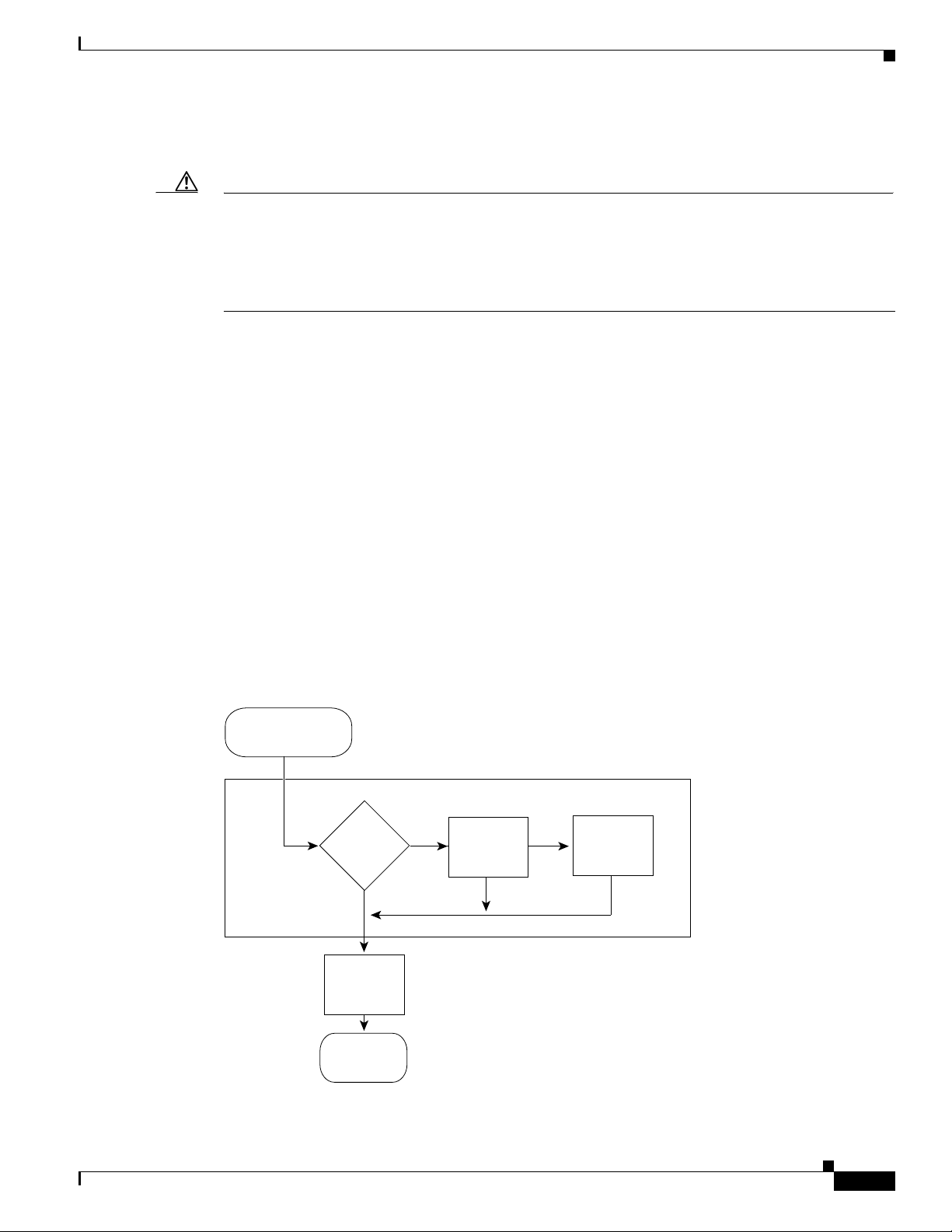
Flowchart of PFC QoS Egress LAN Port Features
Figure 42-7 shows how traffic flows through the QoS features on egress LAN ports.
Figure 42-7 Egress LAN Port Scheduling, Congestion Avoidance, and Marking
Egress CoS Values
For all egress traffic, PFC QoS uses a configurable map to derive a CoS value from the final internal
DSCP value associated with the traffic. PFC QoS sends the derived CoS value to the egress LAN ports
for use in classification and congestion avoidance and to be written into ISL and 802.1Q frames.
Note With Release 12.2(18)SXF5 and later releases, you can configure WS-X6708-10GE ports to use the final
internal DSCP value for egress LAN port classification and congestion avoidance (see the “Configuring
DSCP-Based Queue Mapping” section on page 42-98).
144806
Write CoS
into
frame
ISL or
802.1Q?
IP traffic
from PFC?
Write ToS
byte into
packet
DSCP
rewrite
enabled?
No
No
No
Ye s Ye s
Ye s
Transmit
frame
From
PFC or MSFC
Egress queues and
drop thresholds
PFC3
only

42-14
Cisco 7600 Series Router Cisco IOS Software Configuration Guide, Release 12.2SX
OL-4266-08
Chapter 42 Configuring PFC QoS
Understanding How PFC QoS Works
Egress DSCP Mutation with a PFC3
With a PFC3, you can configure 15 egress DSCP mutation maps to mutate the internal DSCP value
before it is written in the egress ToS byte. You can attach egress DSCP mutation maps to any interface
that PFC QoS supports.
Note • If you configure egress DSCP mutation, PFC QoS does not derive the egress CoS value from the
mutated DSCP value.
• The PFC2 does not support egress DSCP mutation.
Egress ToS Byte
Except when DSCP transparency is enabled, PFC QoS creates a ToS byte for egress IP traffic from the
final internal or mutated DSCP value and sends it to the egress port to be written into IP packets. For
trust DSCP and untrusted IP traffic, the ToS byte includes the original two least-significant bits from the
received ToS byte.
The internal or mutated DSCP value can mimic an IP precedence value (see the “IP Precedence and
DSCP Values” section on page 42-55).
Egress PFC QoS Interfaces
You can attach an output policy map to a Layer 3 interface (either a LAN port configured as a Layer 3
interface or a VLAN interface) to apply a policy map to egress traffic.
Note • Output policies do not support microflow policing.
• With a PFC3, you cannot apply microflow policing to ARP traffic.
• You cannot set a trust state in an output policy.
Egress ACL Support for Remarked DSCP
Note Egress ACL support for remarked DSCP is also known as packet recirculation.
With a PFC3, Release 12.2(18)SXE and later releases support egress ACL support for remarked DSCP,
which enables IP precedence-based or DSCP-based egress QoS filtering to use any IP precedence or
DSCP policing or marking changes made by ingress PFC QoS.
Without egress ACL support for remarked DSCP, egress QoS filtering uses received IP precedence or
DSCP values; it does not use any IP precedence or DSCP changes made by ingress PFC QoS as the result
of policing or marking.
The PFC3 provides egress PFC QoS only for Layer 3-switched and routed traffic on egress Layer 3
interfaces (either LAN ports configured as Layer 3 interfaces or VLAN interfaces).
You configure egress ACL support for remarked DSCP on ingress Layer 3 interfaces (either LAN ports
configured as Layer 3 interfaces or VLAN interfaces).
42-15
Cisco 7600 Series Router Cisco IOS Software Configuration Guide, Release 12.2SX
OL-4266-08
Chapter 42 Configuring PFC QoS
Understanding How PFC QoS Works
On interfaces where egress ACL support for remarked DSCP is configured, the PFC3 processes each
QoS-filtered IP packet twice: once to apply ingress PFC QoS and once to apply egress PFC QoS.
Caution If the router is operating in PFC3A mode with egress ACL support for remarked DSCP configured, when
the PFC3 processes traffic to apply ingress PFC QoS, it applies ingress PFC QoS filtering and ingress
PFC QoS, and incorrectly applies any egress QoS filtering and egress PFC QoS configured on the
ingress interface, which results in unexpected behavior if QoS filtering is configured on an interface
where egress ACL support for remarked DSCP is enabled. This problem does not occur in other
PFC3 modes.
After packets have been processed by ingress PFC QoS and any policing or marking changes have been
made, the packets are processed again on the ingress interface by any configured Layer 2 features (for
example, VACLs) before being processed by egress PFC QoS.
On an interface where egress ACL support for remarked DSCP is configured, if a Layer 2 feature
matches the ingress-QoS-modified IP precedence or DSCP value, the Layer 2 feature might redirect or
drop the matched packets, which prevents them from being processed by egress QoS.
After packets have been processed by ingress PFC QoS and any policing or marking changes have been
made, the packets are processed on the ingress interface by any configured Layer 3 features (for example,
ingress Cisco IOS ACLs, policy based routing (PBR), etc.) before being processed by egress PFC QoS.
The Layer 3 features configured on an interface where egress ACL support for remarked DSCP is
configured might redirect or drop the packets that have been processed by ingress PFC QoS, which
would prevent them from being processed by egress PFC QoS.
Marking on Egress OSM Ports
Ingress PFC QoS sets DSCP values that can be used by the OSM egress QoS features (see Figure 42-8).
Figure 42-8 Egress OSM Port Marking
Transmit
OSM traffic
113090
IP traffic
from PFC?
Write ToS
byte into
packet
No
OSM switching module marking
From PFC or
MSFC
OSM
QoS
Features
DSCP
rewrite
enabled?
No
Ye s Ye s
PFC3
only

42-16
Cisco 7600 Series Router Cisco IOS Software Configuration Guide, Release 12.2SX
OL-4266-08
Chapter 42 Configuring PFC QoS
Understanding How PFC QoS Works
Understanding Classification and Marking
The following sections describe where and how classification and marking occur on the Cisco 7600
series routers:
• Classification and Marking at Trusted and Untrusted Ingress Ports, page 42-16
• Classification and Marking at Ingress OSM Ports, page 42-17
• Classification and Marking on the PFC Using Service Policies and Policy Maps, page 42-18
• Classification and Marking on the MSFC, page 42-19
Classification and Marking at Trusted and Untrusted Ingress Ports
The trust state of an ingress port determines how the port marks, schedules, and classifies received
Layer 2 frames, and whether or not congestion avoidance is implemented. These are the port trust states:
• Untrusted (default)
• Trust IP precedence
• Trust DSCP
• Trust CoS
In all releases, ingress LAN port classification, marking, and congestion avoidance can use Layer 2 CoS
values and do not set Layer 3 IP precedence or DSCP values.
In Release 12.2(18)SXF5 and later releases, you can configure WS-X6708-10GE ports to use received
DSCP values for ingress LAN port classification and congestion avoidance (see the “Configuring
DSCP-Based Queue Mapping” section on page 42-98)
In Releases earlier than Release 12.2(18)SXF5, ingress LAN port classification, marking, and
congestion avoidance use Layer 2 CoS values only.
The following sections describe classification and marking at trusted and untrusted ingress ports:
• Classification and Marking at Untrusted Ingress Ports, page 42-16
• Ingress Classification and Marking at Trusted Ports, page 42-16
Classification and Marking at Untrusted Ingress Ports
PFC QoS Layer 2 remarking marks all frames received through untrusted ports with the port CoS value
(the default is zero).
To map the port CoS value that was applied to untrusted ingress traffic to the initial internal DSCP value,
configure a trust CoS policy map that matches the ingress traffic.
Ingress Classification and Marking at Trusted Ports
You should configure ports to trust only if they receive traffic that carries valid QoS labels. QoS uses the
received QoS labels as the basis of initial internal DSCP value. After the traffic enters the router, you
can apply a different trust state to traffic with a policy map. For example, traffic can enter the router
through a trust CoS port, and then you can use a policy map to trust IP precedence or DSCP, which uses
the trusted value as the basis of the initial internal DSCP value, instead of the QoS label that was trusted
at the port.

42-17
Cisco 7600 Series Router Cisco IOS Software Configuration Guide, Release 12.2SX
OL-4266-08
Chapter 42 Configuring PFC QoS
Understanding How PFC QoS Works
These sections describe classification and marking at trusted ingress ports:
• Ingress Classification and Marking at Trust CoS LAN Ports, page 42-17
• Ingress Classification and Marking at Trust IP Precedence Ports, page 42-17
• Ingress Classification and Marking at Trust DSCP Ports, page 42-17
Ingress Classification and Marking at Trust CoS LAN Ports
You should configure LAN ports to trust CoS only if they receive traffic that carries valid Layer 2 CoS.
When an ISL frame enters the router through a trusted ingress LAN port, PFC QoS accepts the three least
significant bits in the User field as a CoS value. When an 802.1Q frame enters the router through a
trusted ingress LAN port, PFC QoS accepts the User Priority bits as a CoS value. PFC QoS Layer 2
remarking marks all traffic received in untagged frames with the ingress port CoS value.
On ports configured to trust CoS, PFC QoS does the following:
• PFC QoS maps the received CoS value in tagged trust CoS traffic to the initial internal DSCP value.
• PFC QoS maps the ingress port CoS value applied to untagged trusted traffic to the initial internal
DSCP value.
• PFC QoS enables the CoS-based ingress queues and thresholds to provide congestion avoidance.
See the “Understanding Port-Based Queue Types” section on page 42-22 for more information about
ingress queues and thresholds.
Ingress Classification and Marking at Trust IP Precedence Ports
You should configure ports to trust IP precedence only if they receive traffic that carries valid Layer 3
IP precedence. For traffic from trust IP precedence ports, PFC QoS maps the received IP precedence
value to the initial internal DSCP value. Because the ingress port queues and thresholds use Layer 2 CoS,
PFC QoS does not implement ingress port congestion avoidance on ports configured to trust IP
precedence. PFC does not mark any traffic on ingress ports configured to trust IP precedence.
Ingress Classification and Marking at Trust DSCP Ports
You should configure ports to trust DSCP only if they receive traffic that carries valid Layer 3 DSCP.
In Release 12.2(18)SXF5 and later releases, you can enable DSCP-based ingress queues and thresholds
on WS-X6708-10GE ports to provide congestion avoidance (see the “Configuring DSCP-Based Queue
Mapping” section on page 42-98).
In releases earlier than Release 12.2(18)SXF5, the ingress port queues and thresholds use only Layer 2
CoS, and PFC QoS does not implement ingress port congestion avoidance on ports configured to trust
DSCP.
For traffic from trust DSCP ports, PFC QoS uses the received DSCP value as the initial internal DSCP
value. PFC QoS does not mark any traffic on ingress ports configured to trust received DSCP.
Classification and Marking at Ingress OSM Ports
PFC QoS associates CoS zero with all traffic received through ingress OSM ports. You can configure
ingress OSM port trust states that can be used by the PFC to set IP precedence or DSCP values and the
CoS value. You can configure the trust state of each ingress OSM port as follows:
• Untrusted (default)
• Trust IP precedence
• Trust DSCP

42-18
Cisco 7600 Series Router Cisco IOS Software Configuration Guide, Release 12.2SX
OL-4266-08
Chapter 42 Configuring PFC QoS
Understanding How PFC QoS Works
• Trust CoS (CoS is always zero for POS and ATM OSM ports because the port CoS value is not
configurable on POS and ATM OSM ports.)
Classification and Marking on the PFC Using Service Policies and Policy Maps
PFC QoS supports classification and marking with service policies that attach one policy map to these
interface types to apply ingress PFC QoS:
• Each ingress port (except FlexWAN interfaces)
• Each EtherChannel port-channel interface
• Each VLAN interface
With a PFC3, you can attach one policy map to each Layer 3 interface (except FlexWAN interfaces) to
apply egress PFC QoS.
Each policy map can contain multiple policy-map classes. You can configure a separate policy-map class
for each type of traffic handled by the interface. There are two ways to configure filtering in policy-map
classes:
• Access control lists (ACLs)
• Class-map match commands for IP precedence and DSCP values
Policy-map classes specify actions with the following optional commands:
• Policy-map set commands—For untrusted traffic or if ignore port trust is enabled, PFC QoS can use
configured IP precedence or DSCP values as the final internal DSCP value. The “IP Precedence and
DSCP Values” section on page 42-55 shows the bit values for IP precedence and DSCP.
• Policy-map class trust commands—PFC QoS applies the policy-map class trust state to matched
ingress traffic, which then uses the trusted value as the basis of its initial internal DSCP value,
instead of the QoS label that was trusted at the port (if any). In a policy map, you can trust CoS, IP
precedence, or DSCP.
Note A trust CoS policy map cannot restore received CoS in traffic from untrusted ports. Traffic
from untrusted ports always has the port CoS value.
• Aggregate and microflow policers—PFC QoS can use policers to either mark or drop both
conforming and nonconforming traffic.

42-19
Cisco 7600 Series Router Cisco IOS Software Configuration Guide, Release 12.2SX
OL-4266-08
Chapter 42 Configuring PFC QoS
Understanding How PFC QoS Works
Classification and Marking on the MSFC
PFC QoS sends IP traffic to the MSFC with the final internal DSCP values. CoS is equal to
IP precedence in all traffic sent from the MSFC to egress ports.
Figure 42-9 Marking with PFC2 or PFC3 and MSFC2, MSFC2A, or MSFC3
Note Traffic that is Layer 3 switched on the PFC does not go through the MSFC and retains the CoS value
assigned by the PFC.
Policers
These sections describe policers:
• Overview of Policers, page 42-19
• Aggregate Policers, page 42-20
• Microflow Policers, page 42-21
Overview of Policers
Policing allows you to rate limit incoming and outgoing traffic so that it adheres to the traffic forwarding
rules defined by the QoS configuration. Sometimes these configured rules for how traffic should be
forwarded through the system are referred to as a contract. If the traffic does not adhere to this contract,
it is marked down to a lower DSCP value or dropped.
Policing does not buffer out-of-profile packets. As a result, policing does not affect transmission delay.
In contrast, traffic shaping works by buffering out-of-profile traffic, which moderates the traffic bursts.
(PFC QoS does not support shaping.)
144800
To egress
port
IP traffic
from PFC?
Write ToS
byte into
packet
No
Ye s
Multilayer Switch Feature Card (MSFC) marking
From PFC
Route
traffic
CoS =
IP precedence for
all traffic
(not configurable)

42-20
Cisco 7600 Series Router Cisco IOS Software Configuration Guide, Release 12.2SX
OL-4266-08
Chapter 42 Configuring PFC QoS
Understanding How PFC QoS Works
The PFC2 supports only ingress PFC QoS, which includes ingress policing. The PFC3 supports both
ingress and egress PFC QoS, which includes ingress and egress policing. Traffic shaping is supported on
some WAN modules. For more information about traffic shaping on the OSM and FlexWAN modules,
refer to the OSM and FlexWAN documentation at this location:
http://www.cisco.com/univercd/cc/td/doc/product/core/cis7600/cfgnotes/index.htm
Note Policers can act on ingress traffic per-port or per-VLAN. With a PFC3, for egress traffic, the policers can
act per-VLAN only.
You can create policers to do the following:
• Mark traffic
• Limit bandwidth utilization and mark traffic
Aggregate Policers
PFC QoS applies the bandwidth limits specified in an aggregate policer cumulatively to all flows in
matched traffic. For example, if you configure an aggregate policer to allow 1 Mbps for all TFTP traffic
flows on VLAN 1 and VLAN 3, it limits the TFTP traffic for all flows combined on VLAN 1 and VLAN
3 to 1 Mbps.
• You define per-interface aggregate policers in a policy map class with the police command. If you
attach a per-interface aggregate policer to multiple ingress ports, it polices the matched traffic on
each ingress port separately.
• You create named aggregate policers with the mls qos aggregate-policer command. If you attach a
named aggregate policer to multiple ingress ports, it polices the matched traffic from all the ingress
ports to which it is attached.
• Aggregate policing works independently on each DFC-equipped switching module and
independently on the PFC, which supports any non-DFC-equipped switching modules. Aggregate
policing does not combine flow statistics from different DFC-equipped switching modules. You can
display aggregate policing statistics for each DFC-equipped switching module and for the PFC and
any non-DFC-equipped switching modules supported by the PFC.
• Each PFC or DFC polices independently, which might affect QoS features being applied to traffic
that is distributed across the PFC and any DFCs. Examples of these QoS feature are:
–
Policers applied to a port channel interface.
–
Policers applied to a switched virtual interface.
–
Egress policers applied to either a Layer 3 interface or an SVI. Note that PFC QoS performs
egress policing decisions at the ingress interface, on the PFC or ingress DFC.
Policers affected by this restriction deliver an aggregate rate that is the sum of all the independent
policing rates.

42-21
Cisco 7600 Series Router Cisco IOS Software Configuration Guide, Release 12.2SX
OL-4266-08
Chapter 42 Configuring PFC QoS
Understanding How PFC QoS Works
Microflow Policers
PFC QoS applies the bandwidth limit specified in a microflow policer separately to each flow in matched
traffic. For example, if you configure a microflow policer to limit the TFTP traffic to 1 Mbps on VLAN
1 and VLAN 3, then 1 Mbps is allowed for each flow in VLAN 1 and 1 Mbps for each flow in VLAN 3.
In other words, if there are three flows in VLAN 1 and four flows in VLAN 3, the microflow policer
allows each of these flows 1 Mbps.
You can configure PFC QoS to apply the bandwidth limits in a microflow policer as follows:
• You can create microflow policers with up to 63 different rate and burst parameter combinations.
• You create microflow policers in a policy map class with the police flow command.
• You can configure a microflow policer to use only source addresses, which applies the microflow
policer to all traffic from a source address regardless of the destination addresses.
• You can configure a microflow policer to use only destination addresses, which applies the
microflow policer to all traffic to a destination address regardless of the source addresses.
• For MAC-Layer microflow policing, PFC QoS considers MAC-Layer traffic with the same protocol
and the same source and destination MAC-Layer addresses to be part of the same flow, including
traffic with different EtherTypes. With a PFC3, you can configure MAC ACLs to filter IPX traffic.
• With a PFC2, you can configure IPX ACLs to filter IPX traffic. For IPX microflow policing,
PFC QoS considers IPX traffic with the same source network, destination network, and destination
node to be part of the same flow, including traffic with different source nodes or source sockets.
• By default, microflow policers only affect traffic routed by the MSFC. To enable microflow policing
of other traffic, including traffic in bridge groups, enter the mls qos bridged command. With a
PFC2, you must enable bridged mircoflow policing for routed traffic as well.
• With a PFC3, you cannot apply microflow policing to ARP traffic.
• You cannot apply microflow policing to IPv6 multicast traffic.
You can include both an aggregate policer and a microflow policer in each policy map class to police a
flow based on both its own bandwidth utilization and on its bandwidth utilization combined with that of
other flows.
Note If traffic is both aggregate and microflow policed, then the aggregate and microflow policers must both
be in the same policy-map class and each must use the same conform-action and exceed-action
keyword option: drop, set-dscp-transmit, set-prec-transmit, or transmit.
For example, you could create a microflow policer with a bandwidth limit suitable for individuals in a
group, and you could create a named aggregate policer with bandwidth limits suitable for the group as a
whole. You could include both policers in policy map classes that match the group’s traffic. The
combination would affect individual flows separately and the group aggregately.
For policy map classes that include both an aggregate and a microflow policer, PFC QoS responds to an
out-of-profile status from either policer and, as specified by the policer, applies a new DSCP value or
drops the packet. If both policers return an out-of-profile status, then if either policer specifies that the
packet is to be dropped, it is dropped; otherwise, PFC QoS applies a marked-down DSCP value.
Note To avoid inconsistent results, ensure that all traffic policed by the same aggregate policer has the same
trust state.

42-22
Cisco 7600 Series Router Cisco IOS Software Configuration Guide, Release 12.2SX
OL-4266-08
Chapter 42 Configuring PFC QoS
Understanding How PFC QoS Works
With a PFC3, policing uses the Layer 2 frame size. With a PFC2, policing uses the Layer 3 packet size.
You specify the bandwidth utilization limit as a committed information rate (CIR). You can also specify
a higher peak information rate (PIR). Packets that exceed a rate are “out of profile” or “nonconforming.”
In each policer, you specify if out-of-profile packets are to be dropped or to have a new DSCP value
applied to them (applying a new DSCP value is called “markdown”). Because out-of-profile packets do
not retain their original priority, they are not counted as part of the bandwidth consumed by in-profile
packets.
If you configure a PIR, the PIR out-of-profile action cannot be less severe than the CIR out-of-profile
action. For example, if the CIR out-of-profile action is to mark down the traffic, then the PIR
out-of-profile action cannot be to transmit the traffic.
For all policers, PFC QoS uses a configurable global table that maps the internal DSCP value to a
marked-down DSCP value. When markdown occurs, PFC QoS gets the marked-down DSCP value from
the table. You cannot specify marked-down DSCP values in individual policers.
Note • Policing with the conform-action transmit keywords supersedes the ingress LAN port trust state
of matched traffic with trust DSCP or with the trust state defined by a trust policy-map class
command.
• By default, the markdown table is configured so that no markdown occurs: the marked-down DSCP
values are equal to the original DSCP values. To enable markdown, configure the table appropriately
for your network.
• When you apply both ingress policing and egress policing to the same traffic, both the input policy
and the output policy must either mark down traffic or drop traffic. PFC QoS does not support
ingress markdown with egress drop or ingress drop with egress markdown.
Understanding Port-Based Queue Types
Port-based queue types are determined by the ASICs that control the ports. The following sections
describe the queue types, drop thresholds, and buffers that are supported on the Cisco 7600 series router
LAN modules:
• Ingress and Egress Buffers and Layer 2 CoS-Based Queues, page 42-22
• Ingress Queue Types, page 42-24
• Egress Queue Types, page 42-25
• Module to Queue Type Mappings, page 42-26
Ingress and Egress Buffers and Layer 2 CoS-Based Queues
The Ethernet LAN module port ASICs have buffers that are divided into a fixed number of queues. When
congestion avoidance is enabled, PFC QoS uses the traffic’s Layer 2 CoS value to assign traffic to the
queues. The buffers and queues store frames temporarily as they transit the switch. PFC QoS allocates
the port ASIC memory as buffers for each queue on each port.
The Cisco 7600 series router LAN modules support the following types of queues:
• Standard queues
• Strict-priority queues

42-23
Cisco 7600 Series Router Cisco IOS Software Configuration Guide, Release 12.2SX
OL-4266-08
Chapter 42 Configuring PFC QoS
Understanding How PFC QoS Works
The Cisco 7600 series router LAN modules support the following types of scheduling algorithms
between queues:
• Shaped round robin (SRR)—SRR allows a queue to use only the allocated bandwidth.
• Deficit weighted round robin (DWRR)—DWRR keeps track of any lower-priority queue
under-transmission caused by traffic in a higher-priority queue and compensates in the next round.
• Weighted Round Robin (WRR)—WRR does not explicitly reserve bandwidth for the queues. Instead,
the amount of bandwidth assigned to each queue is user configurable. The percentage or weight allocated
to a queue defines the amount of bandwidth allocated to the queue.
• Strict-priority queueing—Strict priority queueing allows delay-sensitive data such as voice to be
dequeued and sent before packets in other queues are dequeued, giving delay-sensitive data preferential
treatment over other traffic. The router services traffic in the strict-priority transmit queue before
servicing the standard queues. After transmitting a packet from a standard queue, the switch checks
for traffic in the strict-priority queue. If the switch detects traffic in the strict-priority queue, it
suspends its service of the standard queue and completes service of all traffic in the strict-priority
queue before returning to the standard queue.
The Cisco 7600 series router LAN modules provides congestion avoidance with these types of
thresholds within a queue:
• Weighted Random Early Detection (WRED)—On ports with WRED drop thresholds, frames with a
given QoS label are admitted to the queue based on a random probability designed to avoid buffer
congestion. The probability of a frame with a given QoS label being admitted to the queue or
discarded depends on the weight and threshold assigned to that QoS label.
For example, if CoS 2 is assigned to queue 1, threshold 2, and the threshold 2 levels are 40 percent
(low) and 80 percent (high), then frames with CoS 2 will not be dropped until queue 1 is at least
40 percent full. As the queue depth approaches 80 percent, frames with CoS 2 have an increasingly
higher probability of being discarded rather than being admitted to the queue. Once the queue is over
80 percent full, all CoS 2 frames are dropped until the queue is less than 80 percent full. The frames
the switch discards when the queue level is between the low and high thresholds are picked out at
random, rather than on a per-flow basis or in a FIFO manner. This method works well with protocols
such as TCP that can adjust to periodic packet drops by backing off and adjusting their transmission
window size.
• Tail-drop thresholds—On ports with tail-drop thresholds, frames with a given QoS label are
admitted to the queue until the drop threshold associated with that QoS label is exceeded;
subsequent frames of that QoS label are discarded until the threshold is no longer exceeded. For
example, if CoS 1 is assigned to queue 1, threshold 2, and the threshold 2 watermark is 60 percent,
then frames with CoS 1 will not be dropped until queue 1 is 60 percent full. All subsequent CoS 1
frames will be dropped until the queue is less than 60 percent full. With some port types, you can
configure the standard receive queue to use both a tail-drop and a WRED-drop threshold by mapping
a CoS value to the queue or to the queue and a threshold. The switch uses the tail-drop threshold for
traffic carrying CoS values mapped only to the queue. The switch uses WRED-drop thresholds for
traffic carrying CoS values mapped to the queue and a threshold. All LAN ports of the same type
use the same drop-threshold configuration.
Note In Release 12.2(18)SXF5 and later releases, you can enable DSCP-based queues and thresholds on
WS-X6708-10GE ports (see the “Configuring DSCP-Based Queue Mapping” section on page 42-98).
The combination of multiple queues and the scheduling algorithms associated with each queue allows the
switch to provide congestion avoidance.
42-24
Cisco 7600 Series Router Cisco IOS Software Configuration Guide, Release 12.2SX
OL-4266-08
Chapter 42 Configuring PFC QoS
Understanding How PFC QoS Works
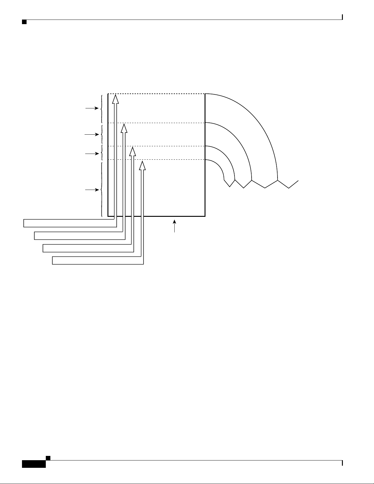
Figure 42-10 illustrates the drop thresholds for a 1q4t ingress LAN port. Drop thresholds in other
configurations function similarly.
Figure 42-10 Receive Queue Drop Thresholds
Ingress Queue Types
To see the queue structure of a LAN port, enter the show queueing interface {ethernet | fastethernet |
gigabitethernet | tengigabitethernet} slot/port | include type command. The command displays one of
the following architectures:
• 1q2t indicates one standard queue with one configurable tail-drop threshold and one
nonconfigurable tail-drop threshold.
• 1q4t indicates one standard queue with four configurable tail-drop thresholds.
• 1q8t indicates one standard queue with eight configurable tail-drop thresholds.
• 2q8t indicates two standard queues, each with eight configurable tail-drop thresholds.
• 8q4t indicates eight standard queues, each with four thresholds, each configurable as either
WRED-drop or tail-drop.
• 8q8t indicates eight standard queues, each with eight thresholds, each configurable as either
WRED-drop or tail-drop.
• 1p1q4t indicates:
–
One strict-priority queue
–
One standard queue with four configurable tail-drop thresholds.
C
o
S
0
a
n
d
1
C
o
S
2
a
n
d
3
C
o
S
4
a
n
d
5
C
o
S
6
a
n
d
7
Traffic is dropped
Drop threshold 4: 100%
Drop threshold 3: 80%
Drop threshold 2: 60%
Drop threshold 1: 50%
Available for
traffic with any
CoS value
Reserved for
CoS 6 and 7
Reserved for
CoS 4 and higher
Reserved for
CoS 2 and higher
Receive queue
(Default values shown)
100% available for CoS 6 and 7
80% available for CoS 4 and 5
60% available for CoS 2 and 3
50% available for CoS 0 and 1
26249

42-25
Cisco 7600 Series Router Cisco IOS Software Configuration Guide, Release 12.2SX
OL-4266-08
Chapter 42 Configuring PFC QoS
Understanding How PFC QoS Works
• 1p1q0t indicates:
–
One strict-priority queue
–
One standard queue with no configurable threshold (effectively a tail-drop threshold at
100 percent).
• 1p1q8t indicates the following:
–
One strict-priority queue
–
One standard queue with these thresholds:
—Eight thresholds, each configurable as either WRED-drop or tail-drop
—One non configurable (100 percent) tail-drop threshold
Egress Queue Types
To see the queue structure of an egress LAN port, enter the show queueing interface {ethernet |
fastethernet | gigabitethernet | tengigabitethernet} slot/port | include type command.
The command displays one of the following architectures:
• 2q2t indicates two standard queues, each with two configurable tail-drop thresholds.
• 1p2q2t indicates the following:
–
One strict-priority queue
–
Two standard queues, each with two configurable WRED-drop thresholds
• 1p3q1t indicates the following:
–
One strict-priority queue
–
Three standard queues with these thresholds:
—One threshold configurable as either WRED-drop or tail-drop
—One nonconfigurable (100 percent) tail-drop threshold
• 1p2q1t indicates the following:
–
One strict-priority queue
–
Two standard queues with these thresholds:
—One WRED-drop threshold
—One non-configurable (100 percent) tail-drop threshold
• 1p3q8t indicates the following:
–
One strict-priority queue
–
Three standard queues, each with eight thresholds, each threshold configurable as either
WRED-drop or tail-drop
• 1p7q4t indicates the following:
–
One strict-priority queue
–
Seven standard queues, each with four thresholds, each threshold configurable as either
WRED-drop or tail-drop

42-26
Cisco 7600 Series Router Cisco IOS Software Configuration Guide, Release 12.2SX
OL-4266-08
Chapter 42 Configuring PFC QoS
Understanding How PFC QoS Works
• 1p7q8t indicates the following:
–
One strict-priority queue
–
Seven standard queues, each with eight thresholds, each threshold configurable as either
WRED-drop or tail-drop
Module to Queue Type Mappings
The following tables show the module to queue structure mapping:
• Supervisor Engine Module QoS Queue Structures
• Ethernet and Fast Ethernet Module Queue Structures
• Gigabit and 10/100/1000 Ethernet Modules
• 10 Gigabit Ethernet Modules
Table 42-2 Supervisor Engine Module QoS Queue Structures
Supervisor Engines
Ingress
Queue and
Drop
Thresholds
Ingress
Queue
Scheduler
Egress
Queue and
Drop
Thresholds
Egress
Queue
Scheduler
Total Buffer
Size
Ingress
Buffer Size
Egress
Buffer Size
WS-SUP720 1p1q4t — 1p2q2t WRR 512 KB 73 KB 439 KB
WS-SUP720-3B
WS-SUP720-3BXL
WS-SUP32-10GE 2q8t WRR 1p3q8t DWRR
SRR
10 Gigabit Ethernet ports 193 MB 105 MB 88 MB
Gigabit Ethernet port 17.7 MB 9.6 MB 8.1 MB
WS-SUP32-GE 17.7 MB 9.6 MB 8.1 MB
WS-X6K-S2U-MSFC2 1p1q4t — 1p2q2t WRR 512 KB 73 KB 439 KB
WS-X6K-S2-MSFC2
WS-X6K-S2-PFC2
Table 42-3 Ethernet and Fast Ethernet Module Queue Structures
Modules
Ingress
Queue and
Drop
Thresholds
Ingress
Queue
Scheduler
Egress
Queue and
Drop
Thresholds
Egress
Queue
Scheduler
Total Buffer
Size
Ingress
Buffer Size
Egress
Buffer Size
WS-X6524-100FX-MM 1p1q0t — 1p3q1t DWRR 1,116 KB 28 KB 1,088 KB
WS-X6548-RJ-21
WS-X6548-RJ-45

42-27
Cisco 7600 Series Router Cisco IOS Software Configuration Guide, Release 12.2SX
OL-4266-08
Chapter 42 Configuring PFC QoS
Understanding How PFC QoS Works
WS-X6324-100FX-MM 1q4t — 2q2t WRR 128 KB 16 KB 112 KB
WS-X6324-100FX-SM
WS-X6348-RJ-45
WS-X6348-RJ-45V
WS-X6348-RJ-21V
WS-X6224-100FX-MT 64 KB 8 KB 56 KB
WS-X6248-RJ-45
WS-X6248-TEL
WS-X6248A-TEL 128 KB 16 KB 112 KB
WS-X6148-RJ-45
WS-X6148-RJ-45V
WS-X6148-45AF
WS-X6148-RJ-21
WS-X6148-RJ-21V
WS-X6148-21AF
WS-X6148X2-RJ-45 1p1q0t — 1p3q1t DWRR 1,116 KB 28 KB 1,088 KB
WS-X6148X2-45AF
WS-X6024-10FL-MT 1q4t — 2q2t WRR 64 KB 8 KB 56 KB
Table 42-4 Gigabit and 10/100/1000 Ethernet Modules
Modules
Ingress
Queue and
Drop
Thresholds
Ingress
Queue
Scheduler
Egress
Queue and
Drop
Thresholds
Egress
Queue
Scheduler
Total Buffer
Size
Ingress
Buffer Size
Egress
Buffer Size
WS-X6816-GBIC 1p1q4t — 1p2q2t WRR 512 KB 73 KB 439 KB
WS-X6748-GE-TX with DFC3 2q8t WRR 1p3q8t DWRR 1.3 MB 166 KB 1.2 MB
WS-X6748-GE-TX with CFC 1q8t —
WS-X6748-SFP with DFC3 2q8t WRR
WS-X6748-SFP with CFC 1q8t —
WS-X6724-SFP with DFC3 2q8t WRR
WS-X6724-SFP with CFC 1q8t —
WS-X6548-GE-TX 1q2t — 1p2q2t WRR 1.4 MB 185 KB 1.2 MB
WS-X6548V-GE-TX
WS-X6548-GE-45AF
Table 42-3 Ethernet and Fast Ethernet Module Queue Structures (continued)
Modules
Ingress
Queue and
Drop
Thresholds
Ingress
Queue
Scheduler
Egress
Queue and
Drop
Thresholds
Egress
Queue
Scheduler
Total Buffer
Size
Ingress
Buffer Size
Egress
Buffer Size

42-28
Cisco 7600 Series Router Cisco IOS Software Configuration Guide, Release 12.2SX
OL-4266-08
Chapter 42 Configuring PFC QoS
PFC QoS Default Configuration
PFC QoS Default Configuration
These sections describe the PFC QoS default configuration:
• PFC QoS Global Settings, page 42-29
• Default Values With PFC QoS Enabled, page 42-30
• Default Values With PFC QoS Disabled, page 42-49
WS-X6516-GBIC 1p1q4t — 1p2q2t WRR 512 KB 73 KB 439 KB
WS-X6516A-GBIC WRR 1 MB 135 KB 946 KB
WS-X6516-GE-TX WRR 512 KB 73 KB 439 KB
WS-X6408-GBIC 1q4t — 2q2t WRR 80 KB 432 KB
WS-X6408A-GBIC 1p1q4t — 1p2q2t WRR 73 KB 439 KB
WS-X6416-GBIC
WS-X6416-GE-MT
WS-X6316-GE-TX
WS-X6148-GE-TX 1q2t — 1.4 MB 185 KB 1.2 MB
WS-X6148V-GE-TX
WS-X6148-GE-45AF
Table 42-5 10 Gigabit Ethernet Modules
Modules
Ingress
Queue and
Drop
Thresholds
Ingress
Queue
Scheduler
Egress
Queue and
Drop
Thresholds
Egress
Queue
Scheduler
Total Buffer
Size
Ingress
Buffer Size
Egress
Buffer Size
WS-X6708-10GE 8q4t DWRR 1p7q4t DWRR
SRR
198 MB 108 MB 90 MB
WS-X6704-10GE with DFC3 8q8t WRR 1p7q8t DWRR 16 MB 2 MB 14 MB
WS-X6704-10GE with CFC 1q8t —
WS-X6502-10GE 1p1q8t — 1p2q1t DWRR 64.2 MB 256 KB 64 MB
WS-X6501-10GEX4
Table 42-4 Gigabit and 10/100/1000 Ethernet Modules
Modules
Ingress
Queue and
Drop
Thresholds
Ingress
Queue
Scheduler
Egress
Queue and
Drop
Thresholds
Egress
Queue
Scheduler
Total Buffer
Size
Ingress
Buffer Size
Egress
Buffer Size

42-29
Cisco 7600 Series Router Cisco IOS Software Configuration Guide, Release 12.2SX
OL-4266-08
Chapter 42 Configuring PFC QoS
PFC QoS Default Configuration
PFC QoS Global Settings
The following global PFC QoS settings apply:
Feature Default Value
PFC QoS global enable state Disabled
PFC QoS port enable state Enabled when PFC QoS is globally enabled
Port CoS value 0
Microflow policing Enabled
IntraVLAN microflow policing Disabled
Port-based or VLAN-based PFC QoS Port-based
Received CoS to initial internal DSCP map
(initial internal DSCP set from received CoS values)
CoS 0 = DSCP 0
CoS 1 = DSCP 8
CoS 2 = DSCP 16
CoS 3 = DSCP 24
CoS 4 = DSCP 32
CoS 5 = DSCP 40
CoS 6 = DSCP 48
CoS 7 = DSCP 56
Received IP precedence to initial internal DSCP map
(initial internal DSCP set from received IP
precedence values)
IP precedence 0 = DSCP 0
IP precedence 1 = DSCP 8
IP precedence 2 = DSCP 16
IP precedence 3 = DSCP 24
IP precedence 4 = DSCP 32
IP precedence 5 = DSCP 40
IP precedence 6 = DSCP 48
IP precedence 7 = DSCP 56
Final internal DSCP to egress CoS map
(egress CoS set from final internal DSCP values)
DSCP 0–7 = CoS 0
DSCP 8–15 = CoS 1
DSCP 16–23 = CoS 2
DSCP 24–31 = CoS 3
DSCP 32–39 = CoS 4
DSCP 40–47 = CoS 5
DSCP 48–55 = CoS 6
DSCP 56–63 = CoS 7
Marked-down DSCP from DSCP map Marked-down DSCP value equals original
DSCP value (no markdown)
Policers None
Policy maps None
Protocol-independent MAC ACL filtering Disabled
VLAN-based MAC ACL QoS filtering Disabled

42-30
Cisco 7600 Series Router Cisco IOS Software Configuration Guide, Release 12.2SX
OL-4266-08
Chapter 42 Configuring PFC QoS
PFC QoS Default Configuration
Default Values With PFC QoS Enabled
These sections list the default values that apply when PFC QoS is enabled:
• Receive-Queue Limits, page 42-30
• Transmit-Queue Limit s, page 42-30
• Bandwidth Allocation Ratios, page 42-31
• Default Drop-Threshold Percentages and CoS Value Mappings, page 42-31
Note The ingress LAN port trust state defaults to untrusted with QoS enabled.
Receive-Queue Limits
Transmit-Queue Limit s
Feature Default Value
2q8t Low priority: 80%
High priority: 20%
8q4t Low priority: 80%
Intermediate queues: 0%
High priority: 20%
8q8t Lowest priority: 80%
Intermediate queues: 0%
Highest priority: 20%
Feature Default Value
2q2t Low priority: 80%
High priority: 20%
1p2q2t Low priority: 70%
High priority: 15%
Strict priority 15%
1p2q1t Low priority: 70%
High priority: 15%
Strict priority 15%
1p3q8t Low priority: 50%
Medium priority: 20%
High priority: 15%
Strict priority 15%
Loading...