


SL-100
Table of contents
 Loading...
Cisco Unified ICM ACD Supplement for Nortel DMS-100/SL-100
Corporate Headquarte rs
Cisco Systems, Inc.
170 West Tasman Drive
San Jose, CA 95134-1706
USA
HU
http://www.cisco.com
UH
Tel: 408 526-4000
800 553-NETS (64387)
Fax: 408 526-4100
February 2010

THE SPECIFICATIONS AND INFORMATION REGARDING THE PRODUCTS IN THIS MANUAL ARE SUBJECT TO CHANGE WITHOUT
NOTICE. ALL STATEMENTS, INFORMATION, AND RECOMMENDATIONS IN THIS MANUAL ARE BELIEVED TO BE ACCURATE BUT ARE
PRESENTED WITHOUT WARRANTY OF ANY KIND, EXPRESS OR IMPLIED. USERS MUST TAKE FULL RESPONSIBILITY FOR THEIR
APPLICATION OF ANY PRODUCTS.
THE SOFTWARE LICENSE AND LIMITED W ARRANTY FOR THE ACCOMPANYING PRODUCT ARE SET FORTH IN THE INFORMATION
PACKET THAT SHIPPED WITH THE PRODUCT AND ARE INCORPORATED HEREIN BY THIS REFERENCE. IF YOU ARE UNABLE TO
LOCATE THE SOFTWARE LICENSE OR LIMITED WARRANTY, CONTACT YOUR CISCO REPRESENTATIVE FOR A COPY.
The Cisco implementation of TCP header compression is an adaptation of a program developed by the University of California, Berkeley (UCB)
as part of UCBs public domain version of the UNIX operating system. All rights reserved. Copyright © 1981, Regents of the University of
California.
NOTWITHSTANDING ANY OTHER WARRANTY HEREIN, ALL DOCUMENT FILES AND SOFTWARE OF THESE SUPPLIERS ARE
PROVIDED "AS IS" WITH ALL FAULTS. CISCO AND THE ABOVE-NAMED SUPPLIERS DISCLAIM ALL WARRANTIES, EXPRESSED OR
IMPLIED, INCLUDING, WITHOUT LIMITATION, THOSE OF MERCHANTABILITY, FITNESS FOR A PARTICULAR PURPOSE AND
NONINFRINGEMENT OR ARISING FROM A COURSE OF DEALING, USAGE, OR TRADE PRACTICE.
IN NO EVENT SHALL CISCO OR ITS SUPPLIERS BE LIABLE FOR ANY INDIRECT, SPECIAL, CONSEQUENTIAL, OR INCIDENTAL
DAMAGES, INCLUDING, WITHOUT LIMITATION, LOST PROFITS OR LOSS OR DAMAGE TO DATA ARISING OUT OF THE USE OR
INABILITY TO USE THIS MANUAL, EVEN IF CISCO OR ITS SUPPLIERS HAVE BEEN ADVISED OF THE POSSIBILITY OF SUCH
DAMAGES.
CCDE, CCENT, CCSI, Cisco Eos, Cisco HealthPresence, Cisco IronPort, the Cisco logo, Cisco Nurse Connect, Cisco Pulse, Cisco SensorBase,
Cisco StackPower, Cisco StadiumVision, Cisco TelePresence, Cisco Unified Computing System, Cisco WebEx, DCE, Flip Channels, Flip for
Good, Flip Mino, Flipshare (Design), Flip Ultra, Flip Video, Flip Video (Design), Instant Broadband, and Welcome to the Human Network are
trademarks; Changing the Way We Work, Live, Play, and Learn, Cisco Capital, Cisco Capital (Design), Cisco:Financed (Stylized), Cisco Store,
Flip Gift Card, and One Million Acts of Green are service marks; and Access Registrar, Aironet, AllTouch, AsyncOS, Bringing the Meeting To
You, Catalyst, CCDA, CCDP, CCIE, CCIP, CCNA, CCNP, CCSP, CCVP, Cisco, the Cisco Certified Internetwork Expert logo, Cisco IOS,
Cisco Lumin, Cisco Nexus, Cisco Press, Cisco Systems, Cisco Systems Capital, the Cisco Systems logo, Cisco Unity, Collaboration Without
Limitation, Continuum, EtherFast, EtherSwitch, Event Center, Explorer, Follow Me Browsing, GainMaker, iLYNX, IOS, iPhone, IronPort, the
IronPort logo, Laser Link, LightStream, Linksys, MeetingPlace, MeetingPlace Chime Sound, MGX, Networkers, Networking Academy, PCNow,
PIX, PowerKEY, PowerPanels, PowerTV, PowerTV (Design), PowerVu, Prisma, ProConnect, ROSA, SenderBase, SMARTnet, Spectrum Expert,
StackWise, WebEx, and the WebEx logo are registered trademarks of Cisco Systems, Inc. and/or its affiliates in the United States and certain
other countries.
All other trademarks mentioned in this document or website are the property of their respective owners. The use of the word partner does not
imply a partnership relationship between Cisco and any other company. (0910R)
Any Internet Protocol (IP) addresses used in this document are not intended to be actual addresses. Any examples, command display output,
and figures included in the document are shown for illustrative purposes only. Any use of actual IP addresses in illustrative content is
unintentional and coincidental.
Cisco Unified ICM ACD Supplement for Nortel DMS-100/SL-100
Copyright © 20
All rights reserved.
10 Cisco Systems, Inc.

iii
Contents
Preface .................................................................................................. vii
1. Overview ......................................................................................... 11
1.1. DMS100 PG with CompuCALL Link .................................................... 12
1.1.1. CCM Matrix Support................................................................... 13
1.2. CompuCALL Interface Requirements and Limitations ..................... 14
1.2.1. CompuCALL Interface Limitations ............................................. 14
1.3. Nortel DMS100 Switch Limitations ..................................................... 15
2. Unified ICM Configuration .............................................................. 17
2.1. Configuring the DMS-100 ACD ............................................................ 18
2.1.1. Configuring the Peripheral ......................................................... 18
2.1.2. Configuring the Peripheral Targets ............................................ 18
2.1.3. Attributing Calls to Unified ICM Routes...................................... 18
2.2. Services ................................................................................................. 18
2.3. Skill Groups........................................................................................... 18
2.4. Configuring the Agents ........................................................................ 19
2.5. Dialed Numbers .................................................................................... 19
2.6. Labels .................................................................................................... 19
2.7. PG CompuCALL Session Configuration ............................................ 20
2.8. PG CompuCALL X.25 Link Configuration .......................................... 21
2.9. Peripheral Monitor Configuration of ACD Positions......................... 21
2.9.1. Transferring Calls to Non-monitored Devices ............................ 25
2.10. CompuCALL Server ........................................................................... 25
2.10.1. Simple Case ............................................................................... 26
2.10.2. Complex Cases .......................................................................... 27
2.10.3. Setup Details .............................................................................. 29

iv Contents
2.11. Support for Walk-Away Reason Codes ............................................ 37
2.12. Object Mapping ................................................................................... 38
2.12.1. Peripheral ................................................................................... 38
2.12.2. Peripheral Targets and Routes .................................................. 38
2.12.3. Trunk Groups ............................................................................. 39
2.12.4. Trunks ........................................................................................ 39
2.12.5. Services ..................................................................................... 39
2.12.6. Default Peripheral Route ............................................................ 40
2.12.7. Skill Groups ................................................................................ 41
2.12.8. Agent .......................................................................................... 42
2.12.9. DMS-100 Agent State to Cisco Agent State Mapping ............... 42
2.12.10. Dialed Numbers................................................................... 43
2.12.11. Labels .................................................................................. 43
2.12.12. Peripheral Monitor Table Entries......................................... 43
2.13. Monitoring Agent Skill Group Assignment Change........................ 43
3. ACD Configuration – Operation Interface ..................................... 45
3.1. DMS-100 CompuCALL Interface Specification (Q218) ..................... 46
3.1.1. CompuCALL Bandwidth Requirements ..................................... 46
3.2. Post-Routing ......................................................................................... 50
4. Eicon Card Configuration .............................................................. 51
4.1. Eicon Card Configuration Details ....................................................... 52
5. Appendix A: DMS100 Switch Datafill Example ............................. 55
6. Index ....................................................................................... Index-1

Contents v
Tables
Table 1: CCM Matrix_1 ........................................................................................ 13
Table 2: CCM Matrix_2 ........................................................................................ 13
Table 3: DMS-100 PG Label Format ................................................................... 20
Table 4: CompuCALL Session Parameters ......................................................... 20
Table 5: CompuCALL Link Parameters ............................................................... 21
Table 6: Extension Formats ................................................................................. 24
Table 7: Param String Formats ............................................................................ 25
Table 8: CompuCALL Server Setup Options ....................................................... 29
Table 9: ACD Link Setup Options ........................................................................ 32
Table 10: Session Object Setup Options ............................................................. 33
Table 11: Application Link Setup Options ............................................................ 35
Table 12: Application Configuration Options........................................................ 36
Table 13: Example of Walk-Away Codes ............................................................. 37
Table 14: Unified ICM to DMS-100 Service Mapping .......................................... 40
Table 15: Unified ICM to DMS-100 Skill Group Mapping ................................... 41
Table 16: Unified ICM to DMS-100 Agent Mapping ............................................. 42
Table 17: CompuCALL Events to Cisco Agent State Mapping............................ 43
Table 18: DMS-100 Switch Capacity ................................................................... 47
Table 19: DMS-100 Switch Statistics Provided by Nortel .................................... 47
Table 20: DMS-100 CompuCALL Message Size................................................. 48
Table 21: DMS-100 Peripheral Gateway Capacity .............................................. 49
Figures
Figure 1: CompuCALL Interface with DMS100 .................................................... 12
Figure 2: Peripheral Monitor Configuration Window ............................................ 23
Figure 3: Peripheral Monitor Configuration with Parameter String ...................... 24
Figure 4: CompuCALL Session: Simple Case ..................................................... 26
Figure 5: CompuCALL Session: Complex Case .................................................. 28
Figure 6: CompuCALL Server Setup ................................................................... 29
Figure 7: ACD Link Setup .................................................................................... 31
Figure 8: Session Object Setup ........................................................................... 33
Figure 9: Application X.25 Link Setup .................................................................. 35
Figure 10: Application Configuration .................................................................... 36


vii
Preface
Purpose
This document contains the specific information you need to maintain a
Nortel DMS-100/SL-100 Switch with CompuCALL Interface in a Cisco
Unified Intelligent Contact Management (Unified ICM) environment. It is
intended to be used as the Nortel DMS-100/SL-100 Switch-specific
companion to the Unified ICM documentation set.
While the other Unified ICM documents cover general topics such as
configuring an overall system and writing scripts to route contact center
requests, the Cisco Unified ICM ACD Supplement for Nortel DMS-100/SL-
100 provides specific information on configuring a DMS-100/SL-100
Switch and making any necessary adjustments to the DMS-100/SL-100
Switch configuration.
Audience
This document is intended for system managers. The reader should
understand Unified ICM functions as described in the Installation and
Setup Guide for Cisco Unified ICM/Contact Center Enterprise & Hosted,
Configuration Guide for Cisco Unified ICM/Contact Center Enterprise &
Hosted, and Scripting and Media Routing Guide for Cisco Unified
ICM/Contact Center Enterprise & Hosted. The reader should also have
specific knowledge of the DMS-100/SL-100 Switch.
Organization
Chapter 1, “Overview”
Chapter 2, “Unified ICM Configuration”
Chapter 3, “ACD Configuration – Operation Interface”
Chapter 4, “Eicon Card Configuration”
Provides an overview of ACD interface and hardware and software
requirements for the DMS-100/SL-100 Switch.
Describes the relationships between the DMS-100/SL-100 Switch
database objects and the Unified ICM database objects. This chapter
also describes DMS-100/SL-100 Switch -specific settings that must be
confirmed in the Unified ICM configuration.
Describes items in the DMS-100/SL-100 Switch configuration that
must be checked to ensure compatibility with the Unified ICM.

viii Preface
Typographic Conventions
Describes the specifics of the Eicon Card Configuration.
Appendix A, “DMS100 Switch Datafill Example”
Provides a Datafill Example on the DMS100 Switch.
This manual uses the following conventions:
Boldface type is used for emphasis; for example:
Real-time information is not stored in the central database.
Italic type indicates one of the following:
A newly introduced term; for example:
A skill group is a collection of agents who share similar skills.
A generic syntax item that you must replace with a specific value;
for example:
IF (condition, true-value, false-value)
A title of a publication; for example:
For more information see the Database Schema Guide for Cisco
Unified ICM/Contact Center Enterprise & Hosted.
Sans serif type with small caps is used to represent keys on your
keyboard; for example:
Press the
An arrow (→) indicates an item from a pull-down menu. For example,
the Save command from the File menu is referenced as File→Save.
Other Publications
For more information on Unified ICM, see the following documents:
Administration Guide for Cisco Unified ICM/Contact Center
Enterprise & Hosted
Installation and Setup Guide for Cisco Unified ICM/Contact Center
Enterprise & Hosted
Configuration Guide for Cisco Unified ICM/Contact Center
Enterprise & Hosted
Scripting and Media Routing Guide for Cisco Unified ICM/Contact
Center Enterprise & Hosted
For information on Cisco Network Applications Manager (NAM), see the
following documents:
Product Description Guide for Cisco Unified ICM Hosted
SHI FT
key to select a range of items.
Setup and Configuration Guide for Cisco Unified ICM Hosted Edition
Multiple-NAM Setup and Configuration Guide for Cisco Unified ICM
Hosted

Preface ix
Obtaining Documentation, Obtaining Support, and Security
Guidelines
For information on obtaining documentation, obtaining support, security
guidelines, and also recommended aliases and general Cisco documents,
see the monthly What's New in Cisco Product Documentation, which also
lists all new and revised Cisco technical documentation, at:
H
http://www.cisco.com/en/US/docs/general/whatsnew/whatsnew.html
Documentation Feedback
You can provide comments about this document by sending email to the
following address: ccbu_docfeedback@cisco.com
We appreciate your comments.

x Preface

11
1. Overview
The DMS100 Peripheral Gateway (PG) monitors agent and call activity on
the DMS100 ACD through the CompuCALL Interface.
For more information about the supported ACD switches, see the
document Cisco Unified ICM Supported Switches (ACDs).
This chapter describes the hardware and software requirements to connect
the Nortel DMS-100/SL-100 Switch to the Unified ICM PG.
12 Overview
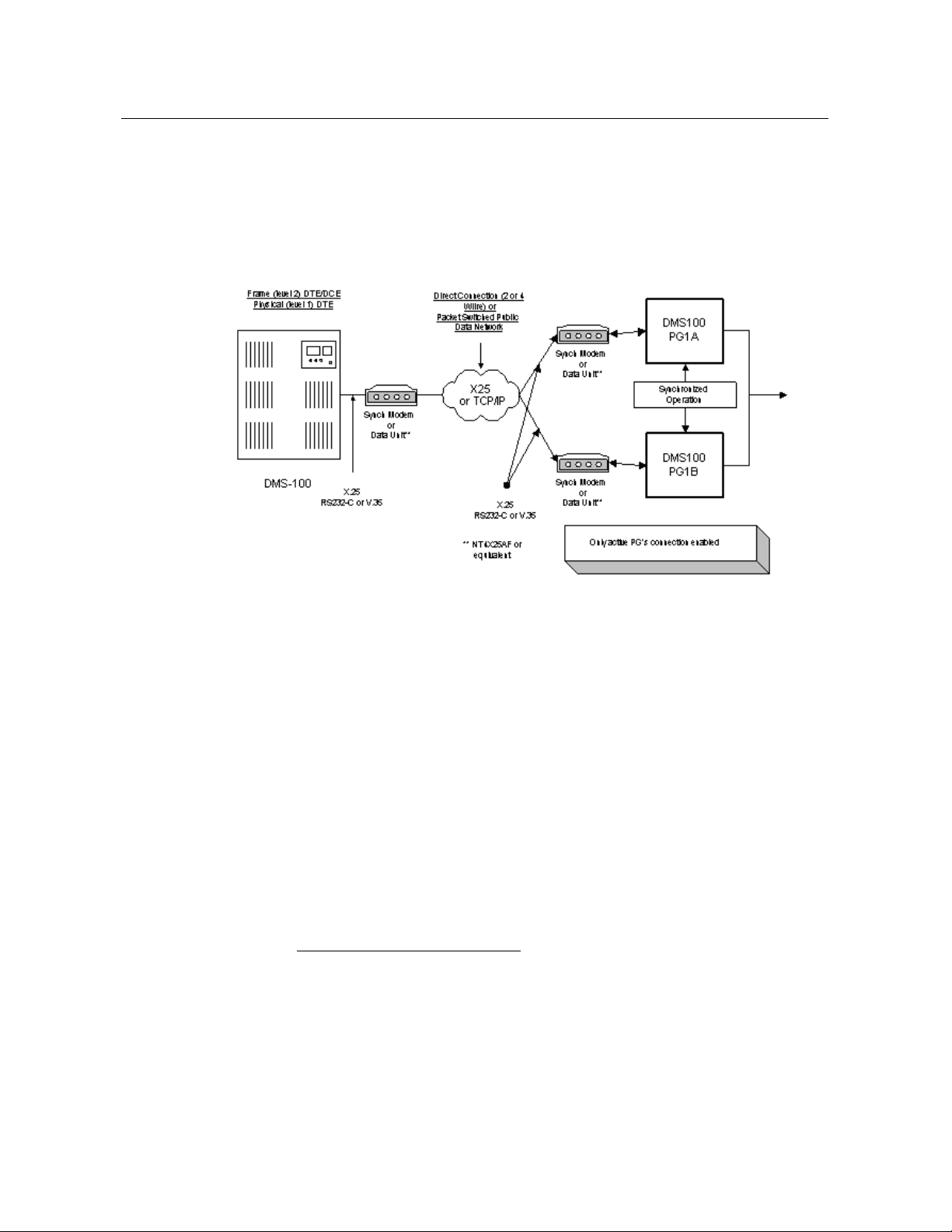
1.1. DMS100 PG with CompuCALL Link
The DMS100 PG can run in simplex or duplex configurations. In a duplex
configuration, only one side of the PG will maintain CompuCALLF1F
X.25 Link or a TCP/IP connection at any given time.
Figure 1: CompuCALL Interface with DMS100
The DMS100 PG can invoke the ANSWER, RELEASE, HOLD and
UNHOLD of incoming calls to ACD agent, Centrex line or Residential
line. The CompuCALLF2F messages, DV-ANSWER-CALL, DVRELEASE-CALL, DV-HOLD-CALL and DV-UNHOLD-CALL allow
the DMS-100 PG to provide third-party call control service to third-party
voice application vendors.
CallsF3F like Three-way Call (3WC) or Call Transfer (CXR) call event
message, DV-Consult-Originated-U, DV-Call-Conferenced-U and DVCall-Transferred that are sent from the DMS-100 switch to allow the
DMS-100 PG to build call conference/transfer model, when the 3WC or
CXR key option, is data-filled on the telephone set.
Note: Since the CompuCALL interface in the release 08.01 does not
support Call Conference (CNF) key, it is required that CNF key not
be data-filled on the telephone set.
1
CompuCALL is a protocol that provides a data communications channel
between a computer and a switch that allows an operating company to provide
coordinated switch-based services, to applications residing on a customer's host
computer in a cost efficient manner.
2
These messages are supported with the CompuCALL interface from release
07.01 onwards.
3
These messages are supported with CompuCALL software release 08.01
onwards.
DMS100 PG with CompuCALL Link 13
PLC
NA100
APC100
PCL
LEC
CDN
ABSK
ABSL
ABSM
CCM02
02
02
CCM03
03
03
CCM04
04
04
04
00
03
CCM05
05
05
02
04
CCM06
06
Note 1
03
01
05
CCM07
07
04 06
CCM08
08 05
02
07
CCM09
09 06
TBD
08/09
CCM10
10 07/08
TBD
10/11
CCM11
11 TBD
TBD
TBD
PLC
EUR100
MSL100
DMS500
PCL
EUR
MSLIVD
LLT
LLDB
CCM02
CCM03 03
CCM04
03
04
04/05
04/05
CCM05
04
05
Configure the ServiceVersion parameter in the DMS-100 PG session
configuration to receive a correct stream of CompuCALL messages. The
DMS-100 PG uses the configured parameter to pass on to the
ServiceVersion field in the DV-Application-Log-On message, which will
be sent during the application logged on session. The ServiceVersion value
uniquely identifies the stream of messages which are corresponding to the
appropriate CompuCALL software release.
For example, the ServiceVersion value for the stream of Switch Computer
Application Interface (SCAI) of the CompuCALL release 08.01 is:
SCAI10.
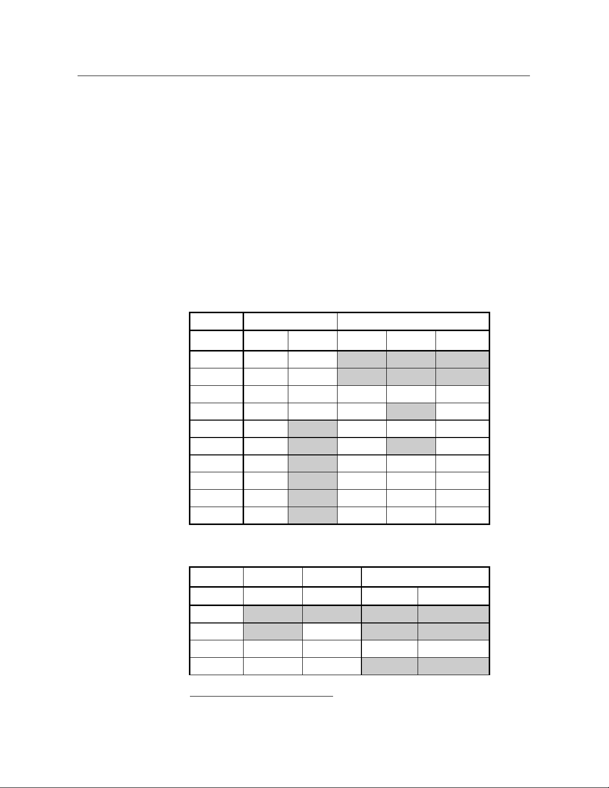
1.1.1. CCM Matrix Support
Since the DMS-100 PG supports up to CCM10, use the following CCM
(Common CM) Matrix tables to find out which PLC and PCL the DMS100 PG supports.
Table 1: CCM Matrix_1
F1F
Table 2: CCM Matrix_2
1
A CCM is one of several types of Development Release Unit (DRU).
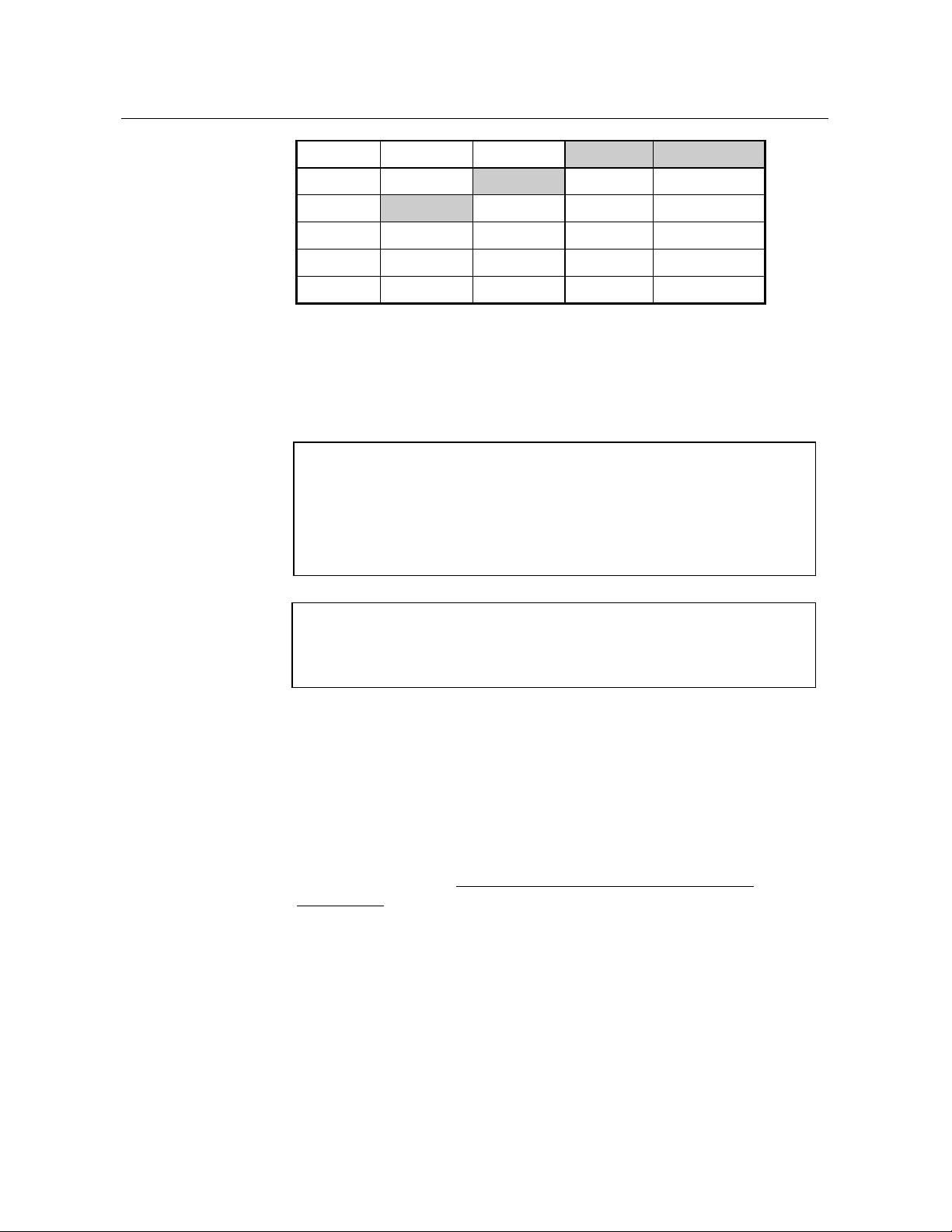
14 Overview
CCM06
05
06
CCM07
06 07
06
CCM08 07
08
TBD
CCM09
08
08
09
TBD
CCM10
09
09
10
TBD
CCM11
10
10
11
TBD
Note: 1. Beginning CCM06 CDN & LEC were combined into a single
PCL (Product CM Load) stream.
2. Shaded area indicates that the DRU was not implemented for the
PCL.
Examples of PCL (Product CM Load) include:
CDN is Canada
LEC is DMS-100/200
MSLDIVD is MS-100 Commercial Market
ABSK is Japan IDC
ABSL is Japan NTT
ABSM is Others (Australia, Philippines, CALA)
LLT is DMS-500 Local/Long Distance/TOPS
LLDB is DMS-500 Local/Long Distance
Examples of PLC (Product Line Center) include:
EUR is Europe
NA is North America
MSL is SL-100
APC is Asian Pacific
DMS -500
1.2. CompuCALL Interface Requirements and Limitations
For optimized performance and utilization of the Cisco Enterprise
Computer telephony Integration (CTI) solution, the CompuCALL software
release 09.01 or above has to been loaded on the DMS-100 Switch.
The CompuCALL software load NA09 allows the DMS100 PIM to know
the Agent Skill Group reassignment when the Call Center supervisor reassigns an Agent from one Skill Group to another Skill Group.
Please see the Section, “Monitoring Agent Skill Group Assignment
Change”UH
monitor Agent Skill Group assignment change.
Note: Install the appropriate patch for CompuCALL software load NA09
1.2.1. CompuCALL Interface Limitations
Any CompuCALL software load below NA09 on the DMS100 Switch
does not support the DMS100 PIM ability to monitor Agent Skill Group
assignment change.
, for detailed information about the ability of the DMS100 to
or above on the DMS100 Switch to enable it to work properly with
DMS100 PG.

Nortel DMS100 Switch Limitations 15
1.3. Nortel DMS100 Switch Limitations
If the PIM receives an out of order sequence message in the LOGOUT or
NOT_READY state, it is due to the inter-working of the DMS100 PIM
and the Nortel DMS100 switch.


17
2. Unified ICM Configuration
In order to properly configure and maintain the database, you need to
understand the relationship between the DMS100 switch database objects
and the database objects.
This chapter describes how objects map between the DMS100 ACD and
the Unified ICM. It also provides DMS100 switch-specific information
that may assist you in configuring the PG through the Configuration
Manager tools.
For detailed information on the Unified ICM Configuration Manager
tools’ user interface, see the Configuration Guide for Cisco Unified
ICM/Contact Center Enterprise and Hosted.

18 Unified ICM Configuration
2.1. Configuring the DMS-100 ACD
To best understand the configuration of the DMS-100 ACD, begin with the
DMS-100 documentation shipped with your switch. The information
provided here is meant to supplement and not to replace the Nortel DMS100 documentation.
2.1.1. Configuring the Peripheral
The “Configure a PG” option in Configure ICM automatically creates a
peripheral object with the appropriate defaults for a DMS-100 peripheral.
If desired, these values can be modified through the peripheral screen in
Configure ICM.
The “Available Holdoff Delay” setting will be used by all Skill Groups for
this peripheral that do not explicitly specify a value for the “Available
Holdoff Delay” at the Skill Group level.
2.1.2. Configuring the Peripheral Targets
A peripheral target should be configured for each combination of Network
Trunk Group and DNIS that can receive ACD calls. Peripheral targets
must also be configured for translation routing
2.1.3. Attributing Calls to Unified ICM Routes
For route statistics, the PG attributes calls to the routes by looking for a
peripheral target that matches the Trunk Group and DNIS for the call and
using the route associated with that peripheral target. If no matching
peripheral target is found, then the call is attributed to the default route for
the peripheral (if one is configured).
2.2. Services
See the Services the Unified ICM services.
2.3. Skill Groups
See the Skill Groups configure Unified ICM Skill Groups.
The “Available Holdoff Delay” should be set to the value of the Variable
WrapUp for this ACD DN. This value is left as “Use Peripheral Default,”
then the default value configured for this peripheral will be used.
The DMS-100 switch does not strictly associate call WrapUp time with
individual calls. The DMS-100 tracks the total time spent by an Agent in
the NotReady state. The Average Work Time is calculated as (ACD
TalkTime + NotReady Time) / Calls Answered.
The Agent can enter the NotReady state at any time and begin
accumulating NotReady Time.
section X2.12.5X, for specifics about when to configure
section X2.12.7X, for a discussion of when to

Labels 19
There are two methods Agents can associate WrapUp time with individual
calls:
• When the Agent issues the NotReady feature (manually or via
CompuCALL SetFeature) while active on a call. When the call is
completed, the Agent will be placed in the NotReady state.
• Through Variable WrapUp feature available on the DMS-100. The
Unified ICM does not receive an indication that the Agent is in the
NotReady State when the call terminates.
The PIM uses the AvailableHoldoffDelay setting to determine when to
place the Agent in the Ready State once the call is released. It is
applicable to all calls for the Peripheral or Skill Group. The
AvailableHoldoffDelay timer on the DMS100 PG must match the Variable
WrapUp for the ACD DN that the agents belong to. If the timer
configuration is incorrect, an agent state mismatch occurs between the
DMS100 PG and the DMS100 ACD.
2.4. Configuring the Agents
See the Agent
agents in the Unified ICM.
section X2.12.8X, for a discussion of configuring DMS-100
2.5. Dialed Numbers
See the Dialed Numbers configuring dialed numbers for DMS-100 Peripherals in the Unified ICM.
2.6. Labels
Each destination to which Post Routed calls should be routed should have
a label configured with the label string set to the destination as it would be
dialed from a phone set. For example, labels may be configured to route
calls to a Primary ACD DN, Supplementary ACD DN, or Secondary DN.
You can assign dynamic call-related information, hostCallData in the
Unified ICM label configuration. The DMS-100 PG will send
hostCallData to the switch; the switch saves the hostCallData, and sends it
to another host application in any subsequent switch-host messages. A
HostCallData is an octet string of a maximum 10 bytes.
The “Label” filed in Label Configuration dialog under the Configure
ICM application has the following two formats:
section X2.12.10X, for a discussion of
Loading...