


 Loading...
Cisco EtherSwitch Service Modules Feature
Guide
Note This document describes the Cisco EtherSwitch service module only. For information about the Cisco Ethernet switch network module, see “Connecting Ethernet Switch Network Modules to a Network” at the following URL: http://www.cisco.com/en/US/products/hw/modules/ps2797/products_module_installation_guide_chapt er09186a00800b168c.html
The Cisco EtherSwitch service modules (NME-16ES-1G, NME-16ES-1G-P, NME-X-23ES-1G, NME-X-23ES-1G-P, NME-XD-48ES-2S-P, and NME-XD-24ES-1S-P) provide Cisco modular access routers the ability to stack Cisco EtherSwitch service modules as Layer 2 switches using Cisco StackWise technology. The Cisco EtherSwitch service modules are supported by either the IP base image (formerly known as standard multilayer image [SMI]) or the IP services image (formerly known as the enhanced multilayer image [EMI]). The IP base image provides Layer 2+ features, including access control lists (ACLs), quality of service (QoS), static routing, and the Routing Information Protocol (RIP). The IP services image provides a richer set of enterprise-class features, including Layer 2+ features and full Layer 3 routing (IP unicast routing, IP multicast routing, and fallback bridging). To distinguish it from the Layer 2+ static routing and RIP, the IP services image includes protocols such as the Enhanced Interior Gateway Routing Protocol (EIGRP) and the Open Shortest Path First (OSPF) Protocol.
Feature History for the Cisco EtherSwitch Service Modules (NME-16ES-1G-P, NME-X-23ES-1G-P,
NME-XD-24ES-1S-P, NME-XD-48ES-2S-P)
Release |
Modification |
12.2(25)EZ (switch software) |
This feature was introduced. |
|
|
12.3(14)T (router software) |
This feature was introduced. |
|
|
Feature History for the Cisco EtherSwitch Service Modules (NME-16ES-1G, NME-X-23ES-1G)
Release |
Modification |
12.2(25)SEC (switch software) |
This feature was introduced. |
|
|
12.3(14)T3 (router software) |
This feature was introduced. |
|
|
Corporate Headquarters:
Cisco Systems, Inc., 170 West Tasman Drive, San Jose, CA 95134-1706 USA
Copyright © 2005 Cisco Systems, Inc. All rights reserved.

Cisco EtherSwitch Service Modules Feature Guide
Contents
Finding Support Information for Platforms and Cisco IOS Software Images
Use Cisco Feature Navigator to find information about platform support and Cisco IOS software image support. Access Cisco Feature Navigator at http://www.cisco.com/go/fn. You must have an account on Cisco.com. If you do not have an account or have forgotten your username or password, click Cancel at the login dialog box and follow the instructions that appear.
Contents
•Prerequisites for the Cisco EtherSwitch Service Modules, page 2
•Information About the Cisco EtherSwitch Service Modules, page 2
•How to Configure the Cisco EtherSwitch Service Module, page 33
•How to Configure the Cisco EtherSwitch Service Module in a Switch Stack, page 50
•How to Configure a Switch Cluster, page 57
•Upgrading the Cisco EtherSwitch Service Module Software, page 63
•Troubleshooting the Cisco EtherSwitch Service Module Software, page 66
•Switch Stack Configuration Scenarios, page 78
•Network Configuration Examples, page 81
•Additional References, page 87
Prerequisites for the Cisco EtherSwitch Service Modules
The Cisco IOS version on the Cisco EtherSwitch service modules must be compatible with the Cisco IOS software release and feature set on the router. See the “Feature History for the Cisco EtherSwitch Service Modules (NME-16ES-1G-P, NME-X-23ES-1G-P, NME-XD-24ES-1S-P, NME-XD-48ES-2S-P)” section on page 1 and the “Feature History for the Cisco EtherSwitch Service Modules (NME-16ES-1G, NME-X-23ES-1G)” section on page 1.
•To view the router, Cisco IOS software release and feature set, enter the show version command in privileged EXEC mode.
•To view the Cisco EtherSwitch service module IOS version, enter the dir flash: command in privileged EXEC mode.
Information About the Cisco EtherSwitch Service Modules
This section describes the features and some important concepts about the Cisco EtherSwitch service modules:
•Hardware Overview, page 3
•Software Features and Benefits, page 4
•Cisco StackWise Concepts, page 12
•Clustering Concepts, page 20
Cisco IOS Release 12.2(25)SEC
2

Cisco EtherSwitch Service Modules Feature Guide
Information About the Cisco EtherSwitch Service Modules
Hardware Overview
Cisco EtherSwitch service modules are modules to which you can connect devices such as Cisco IP phones, Cisco wireless access points, workstations, and other network devices such as servers, routers, and switches.
Note |
Cisco EtherSwitch service module models NME-16ES-1G and NME-X-23ES-1G do not support IP |
|
|
|
phones. |
|
|
|
|
|
The Cisco EtherSwitch service modules can be deployed as backbone switches, aggregating 10BASE-T, |
|
|
100BASE-TX, and 1000BASE-T Ethernet traffic from other network devices. |
|
|
You can manage the Cisco EtherSwitch service modules as a single switch unit or as a set of switches |
|
|
forming a switching stack that acts as a single entity. The stacking ports on the Cisco StackWise |
|
|
EtherSwitch NME-XD-24ES-1S-P service module are used to connect the switches or other Cisco |
|
|
EtherSwitch service modules in a stack. If the Cisco EtherSwitch service modules are not connected |
|
|
using Cisco StackWise ports, the Cisco EtherSwitch service modules are managed individually. For |
|
|
information about which Cisco routers support the Cisco EtherSwitch service modules, see the Cisco |
|
|
Network Modules Hardware Installation Guide. |
|
|
|
Note |
• You can install only one Cisco StackWise EtherSwitch NME-XD-24ES-1S-P service module in a |
|
|
|
single router chassis. |
|
|
• You can install up to two Cisco EtherSwitch service modules in a single router chassis (in Cisco |
|
|
3845, Cisco 3825, Cisco 2851, and Cisco 2821 routers) or up to four Cisco EtherSwitch |
|
|
NME-16ES-1G-P service modules in the Cisco 3745 or Cisco 3845 routers. |
|
|
• Installing more than two Cisco EtherSwitch service modules in a router chassis requires specific |
|
|
cabling. For information about cabling multiple Cisco EtherSwitch service modules, see the Cisco |
|
|
Network Modules Hardware Installation Guide at the following URL: |
|
|
http://www.cisco.com/en/US/products/hw/modules/ps2797/products_module_installation_guide_b |
|
|
ook09186a00802d2910.html |
|
|
|
The six types of Cisco EtherSwitch service modules are:
•NME-16ES-1G—Standard single-wide Cisco EtherSwitch service module with 16 10/100-Mbps ports, and 1 10/100/1000 Gigabit Ethernet port.
•NME-16ES-1G-P—Standard single-wide Cisco EtherSwitch service module with 16 10/100-Mbps ports with Power over Ethernet (PoE), and 1 10/100/1000 Gigabit Ethernet port.
Note The 10/100/1000 Gigabit Ethernet port on the 16-port Cisco EtherSwitch service module does not support PoE.
•NME-X-23ES-1G—Extended single-wide Cisco EtherSwitch service module with 23 10/100-Mbps ports and 1 10/100/1000 Gigabit Ethernet port.
•NME-X-23ES-1G-P—Extended single-wide Cisco EtherSwitch service module with
23 10/100-Mbps PoE ports and 1 10/100/1000 Gigabit Ethernet port. All ports support PoE.
Cisco IOS Release 12.2(25)SEC
3

Cisco EtherSwitch Service Modules Feature Guide
Information About the Cisco EtherSwitch Service Modules
•NME-XD-48ES-2S-P—Extended double-wide Cisco EtherSwitch service module with
48 10/100-Mbps PoE ports, and 2 small form-factor pluggable (SFP) Gigabit Ethernet service module ports
•NME-XD-24ES-1S-P—Extended double-wide Cisco EtherSwitch service module with 24 10/100-Mbps PoE ports, 1 SFP port, and 2 Cisco StackWise ports
For complete information about the Cisco EtherSwitch service modules hardware, see the Cisco Network Modules Hardware Installation Guide at the following URL:
http://www.cisco.com/en/US/products/hw/modules/ps2797/products_module_installation_guide_book 09186a00802d2910.html
Software Features and Benefits
The Cisco EtherSwitch service modules are shipped with either of these software images installed:
•IP base image, which provides Layer 2+ features (enterprise-class intelligent services). These features include access control lists (ACLs), quality of service (QoS), static routing, and the Hot Standby Router Protocol (HSRP) and the Routing Information Protocol (RIP). Cisco EtherSwitch service modules with the IP base image installed can be upgraded to the IP services image.
•IP services image, which provides a richer set of enterprise-class intelligent services. It includes all IP base image features plus full Layer 3 routing (IP unicast routing, IP multicast routing, and fallback bridging). To distinguish it from the Layer 2+ static routing and RIP, the IP services image includes protocols such as the Enhanced Interior Gateway Routing Protocol (EIGRP) and the Open Shortest Path First (OSPF) Protocol.
Some features noted in this section are available only on the cryptographic versions of the IP base image and IP services image. You must obtain authorization to use this feature and to download the cryptographic version of the software from Cisco.com.
The Cisco EtherSwitch service module has these features and benefits:
•Ease-of-Use and Ease-of-Deployment Features, page 5
•Performance Features, page 5
•Management Options, page 6
•Manageability Features, page 7
•Availability Features, page 7
•VLAN Features, page 8
•Security Features, page 9
•QoS and CoS Features, page 10
•Power-over-Ethernet Features, page 11
•Monitoring Features, page 11
Cisco IOS Release 12.2(25)SEC
4

Cisco EtherSwitch Service Modules Feature Guide
Information About the Cisco EtherSwitch Service Modules
Ease-of-Use and Ease-of-Deployment Features
•Express Setup for quickly configuring a Cisco EtherSwitch service module for the first time with basic IP information, contact information, Cisco EtherSwitch service module and Telnet passwords, and Simple Network Management Protocol (SNMP) information through a browser-based program.
•Graphical user interfaces (GUIs) for easier Cisco EtherSwitch service module configuration and monitoring. For more information about these GUIs, see the “Management Options” section on page 6.
•User-defined and Cisco-default SmartPorts macros for creating custom Cisco EtherSwitch service module configurations for simplified deployment across the network.
•Cisco StackWise technology for these uses:
–Connecting up to nine Cisco EtherSwitch service modules through Cisco StackWise ports and operating as a single switch in the network.
–Using a single IP address and configuration file to manage the entire switch stack.
–Automatic Cisco IOS software version-check of new stack members with the option to automatically load images from the stack master or from a TFTP server.
–Adding, removing, and replacing Cisco EtherSwitch service modules in the stack without disrupting the operation of the stack.
–Provisioning a new member for a switch stack with the offline configuration feature. You can configure the interface configuration for a specific stack member number in advance. The switch stack retains this information across stack reloads whether or not the provisioned Cisco EtherSwitch service module is part of the stack.
–Displaying stack-ring activity statistics (the number of frames sent by each stack member to the ring).
Performance Features
•Autosensing of port speed and autonegotiation of duplex mode on all Cisco EtherSwitch service module ports for optimizing bandwidth
•Automatic-medium-dependent interface crossover (Auto-MDIX) capability on 10/100-Mbps interfaces that enables the interface to automatically detect the required cable connection type (straight-through or crossover) and to configure the connection appropriately
•Up to 32 Gbps of forwarding rates in a switch stack
•EtherChannel for enhanced fault tolerance and for providing up to 800 Mbps (Fast EtherChannel) of full-duplex bandwidth between Cisco EtherSwitch service modules, routers, and servers
•Port Aggregation Protocol (PAgP) and Link Aggregation Control Protocol (LACP) for automatic creation of EtherChannel links
•Forwarding of Layer 2 and Layer 3 packets at gigabit-per-second line rate across the Cisco EtherSwitch service modules in the stack
•Per-port storm control for preventing broadcast, multicast, and unicast storms
•Port blocking on forwarding unknown Layer 2 unknown unicast, multicast, and bridged broadcast traffic
Cisco IOS Release 12.2(25)SEC
5

Cisco EtherSwitch Service Modules Feature Guide
Information About the Cisco EtherSwitch Service Modules
•Cisco Group Management Protocol (CGMP) server support and Internet Group Management Protocol (IGMP) snooping for IGMP versions 1, 2, and 3:
–(For CGMP devices) CGMP for limiting multicast traffic to specified end stations and reducing overall network traffic
–(For IGMP devices) IGMP snooping for efficiently forwarding multimedia and multicast traffic
•IGMP report suppression for sending only one IGMP report per multicast router query to the multicast devices (supported only for IGMPv1 or IGMPv2 queries)
•Multicast VLAN registration (MVR) to continuously send multicast streams in a multicast VLAN while isolating the streams from subscriber VLANs for bandwidth and security reasons
•IGMP filtering for controlling the set of multicast groups to which hosts on a Cisco EtherSwitch service module port can belong
•IGMP throttling for configuring the action when the maximum number of entries is in the IGMP forwarding table
Management Options
•Device manager—The device manager provides simplified management for a single
Cisco EtherSwitch service module. Its features, such as SmartPorts and color-coded graphs, make it easier to configure and monitor the Cisco EtherSwitch service module. The device manager is already installed on the Cisco EtherSwitch service module. After the Cisco EtherSwitch service module is configured through the Express Setup program or through the CLI-based setup program, the device manager is accessible through a Microsoft Internet Explorer or Netscape Navigator browser session. For more information, see the device manager online help.
•Cisco Network Assistant—Cisco Network Assistant provides a comprehensive set of features for managing single and multiple devices, including Cisco EtherSwitch service module clusters, through a GUI. This application must be downloaded from Cisco.com and installed on your PC. You can learn more about Network Assistant at this URL:
http://www.cisco.com/go/NetworkAssistant
•CLI—The Cisco IOS CLI software is enhanced to support desktop-switching and multilayer-switching features. You can access the CLI either by connecting your management station directly to the Cisco EtherSwitch service module console port or by using Telnet from a remote management station. You can manage the switch stack by connecting to the console port of any stack member. For more information about the Cisco EtherSwitch service module CLI, see the
Catalyst 3750 Switch Command Reference, Cisco IOS Release 12.2 at the following URL: http://www.cisco.com/en/US/products/hw/switches/ps5023/prod_command_reference_list.html
•SNMP—SNMP management applications such as CiscoWorks2000 LAN Management Suite (LMS) and HP OpenView. You can manage from an SNMP-compatible management station that is running platforms such as HP OpenView or SunNet Manager. The Cisco EtherSwitch service module supports a comprehensive set of MIB extensions and four remote monitoring (RMON) groups. For more information about using SNMP, see the Catalyst 3750 Switch Software Configuration Guide, Cisco IOS Release 12.2 at the following URL:
http://www.cisco.com/univercd/cc/td/doc/product/lan/cat3750/index.htm
Cisco IOS Release 12.2(25)SEC
6

Cisco EtherSwitch Service Modules Feature Guide
Information About the Cisco EtherSwitch Service Modules
Manageability Features
Note The encrypted Secure Shell (SSH) feature listed in this section is available only on the cryptographic versions of the Cisco EtherSwitch service module software image.
•Cisco IE 2100 Series CNS embedded agents for automating Cisco EtherSwitch service module management as well as configuration storage and delivery.
•Dynamic Host Configuration Protocol (DHCP) for automating configuration of Cisco EtherSwitch service module information (such as IP address, default gateway, hostname, and Domain Name System [DNS] and Trivial File Transfer Protocol [TFTP] server names)
•DHCP relay agent information (option 82) for subscriber identification and IP address management
•DHCP relay for forwarding User Datagram Protocol (UDP) broadcasts, including IP address requests, from DHCP clients
•DHCP server for automatic assignment of IP addresses and other DHCP options to IP hosts
•Directed unicast requests to a DNS server for identifying a Cisco EtherSwitch service module through its IP address and its corresponding hostname and to a TFTP server for administering software upgrades from a TFTP server
•Address Resolution Protocol (ARP) for identifying a Cisco EtherSwitch service module through its IP address and its corresponding Media Access Control (MAC) address
•Unicast MAC address filtering to drop packets with specific source or destination MAC addresses
•Cisco Discovery Protocol (CDP) versions 1 and 2 for network topology discovery and mapping between the Cisco EtherSwitch service module and other Cisco devices on the network
•Network Time Protocol (NTP) for providing a consistent time stamp to all Cisco EtherSwitch service modules from an external source
•Cisco IOS File System (IFS) for providing a single interface to all file systems that the Cisco EtherSwitch service module uses
•In-band management access for up to 16 simultaneous Telnet connections for multiple CLI-based sessions over the network
•In-band management access for up to five simultaneous, encrypted SSH connections for multiple CLI-based sessions over the network (requires the cryptographic versions of the Cisco EtherSwitch service module software image)
•In-band management access through SNMP versions 1 and 2c, and 3 GET and SET requests
Availability Features
•HSRP for command Cisco EtherSwitch service module and Layer 3 router redundancy.
•Automatic stack master re-election for replacing stack masters that become unavailable (failover support).
The newly elected stack master begins accepting Layer 2 traffic in less than 1 second and Layer 3 traffic between 3 to 5 seconds.
•Cross-stack EtherChannel for providing redundant links across the switch stack.
•UniDirectional Link Detection (UDLD) and aggressive UDLD for detecting and disabling unidirectional links on fiber-optic interfaces caused by incorrect fiber-optic wiring or port faults.
Cisco IOS Release 12.2(25)SEC
7

Cisco EtherSwitch Service Modules Feature Guide
Information About the Cisco EtherSwitch Service Modules
•IEEE 802.1D Spanning Tree Protocol (STP) for redundant backbone connections and loop-free networks. STP has these features:
–Up to 128 spanning-tree instances supported.
–Per-VLAN spanning-tree plus (PVST+) for balancing load across VLANs.
–Rapid PVST+ for balancing load across VLANs and providing rapid convergence of spanning-tree instances.
–UplinkFast, cross-stack UplinkFast, and BackboneFast for fast convergence after a spanning-tree topology change and for achieving load balancing between redundant uplinks, including gigabit uplinks and cross-stack gigabit uplinks.
•IEEE 802.1s Multiple Spanning Tree Protocol (MSTP) for grouping VLANs into a spanning-tree instance and for providing multiple forwarding paths for data traffic and load balancing and IEEE 802.1w Rapid Spanning Tree Protocol (RSTP) for rapid convergence of the spanning tree by immediately transitioning root and designated ports to the forwarding state.
•Optional spanning-tree features available in PVST+, rapid PVST+, and MSTP mode:
–Port Fast for eliminating the forwarding delay by enabling a port to immediately transition from the blocking state to the forwarding state.
–BPDU guard for shutting down Port Fast-enabled ports that receive bridge protocol data units (BPDUs).
–BPDU filtering for preventing a Port Fast-enabled port from sending or receiving BPDUs.
–Root guard for preventing switches outside the network core from becoming the spanning-tree root.
–Loop guard for preventing alternative or root ports from becoming designated ports because of a failure that leads to a unidirectional link.
•Equal-cost routing for link-level and Cisco EtherSwitch service module-level redundancy.
•Redundant power supply (RPS) support through the Cisco 2811, 2821, 2851, 3825, and 3845 integrated services routers (ISR). When an AC-IP power supply is installed, RPS is available for ISRs as well as PoE.
VLAN Features
•Support for VLAN IDs in the full 1 to 4094 range allowed by the IEEE 802.1Q standard.
•The VLAN ID to which the port belongs (also known as its VLAN membership). The default is 1 for all ports.
•VLAN Query Protocol (VQP) for dynamic VLAN membership.
•Inter-Switch Link (ISL) and IEEE 802.1Q trunking encapsulation on all ports for network moves, adds, and changes; management and control of broadcast and multicast traffic; and network security by establishing VLAN groups for high-security users and network resources.
•Dynamic Trunking Protocol (DTP) for negotiating trunking on a link between two devices and for negotiating the type of trunking encapsulation (802.1Q or ISL) to be used.
•VLAN Trunking Protocol (VTP) and VTP pruning for reducing network traffic by restricting flooded traffic to links destined for stations receiving the traffic.
Cisco IOS Release 12.2(25)SEC
8

Cisco EtherSwitch Service Modules Feature Guide
Information About the Cisco EtherSwitch Service Modules
•Voice VLAN for creating subnets for voice traffic from Cisco IP phones.
•VLAN 1 minimization for reducing the risk of spanning-tree loops or storms by allowing VLAN 1 to be disabled on any individual VLAN trunk link. With this feature enabled, no user traffic is sent or received on the trunk. The Cisco EtherSwitch service module CPU continues to send and receive control protocol frames.
Security Features
Note The Kerberos feature listed in this section is available only on the cryptographic versions of the Cisco EtherSwitch service module software image.
•Password-protected access (read-only and read-write access) to management interfaces for protection against unauthorized configuration changes
•Multilevel security for a choice of security level, notification, and resulting actions
•Static MAC addressing for ensuring security
•Protected port option for restricting the forwarding of traffic to designated ports on the same Cisco EtherSwitch service module
•Port security option for limiting and identifying MAC addresses of the stations allowed to access the port
•Port security aging to set the aging time for secure addresses on a port
•BPDU guard for shutting down a Port Fast-configured port when an invalid configuration occurs
•Standard and extended IP access control lists (ACLs) for defining security policies in both directions on routed interfaces (router ACLs) and VLANs and inbound on Layer 2 interfaces (port ACLs)
•Extended MAC access control lists for defining security policies in the inbound direction on Layer 2 interfaces
•VLAN ACLs (VLAN maps) for providing intra-VLAN security by filtering traffic based on information in the MAC, IP, and TCP/User Datagram Protocol (UDP) headers
•Source and destination MAC-based ACLs for filtering non-IP traffic
•DHCP snooping to filter untrusted DHCP messages between untrusted hosts and DHCP servers
•IEEE 802.1x port-based authentication to prevent unauthorized devices (clients) from gaining access to the network
–802.1x with VLAN assignment for restricting 802.1x-authenticated users to a specified VLAN
–802.1x with port security for controlling access to 802.1x ports
–802.1x with voice VLAN to permit IP phone access to the voice VLAN regardless of the authorized or unauthorized state of the port
–802.1x with guest VLAN to provide limited services to non-802.1x-compliant users
•TACACS+, a proprietary feature for managing network security through a TACACS server
•RADIUS for verifying the identity of, granting access to, and tracking the actions of remote users through authentication, authorization, and accounting (AAA) services
Cisco IOS Release 12.2(25)SEC
9

Cisco EtherSwitch Service Modules Feature Guide
Information About the Cisco EtherSwitch Service Modules
•Kerberos security system to authenticate requests for network resources by using a trusted third party (requires the cryptographic versions of the Cisco EtherSwitch service module software image)
•802.1Q tunneling to allow customers with users at remote sites across a service provider network to keep VLANs segregated from other customers, and Layer 2 protocol tunneling to ensure that the customer network has complete STP, CDP, and VTP information about all users (available on the Cisco EtherSwitch service module but not on the integrated services router [ISR])
QoS and CoS Features
•Automatic QoS (auto-QoS) to simplify the deployment of existing QoS features by classifying traffic and configuring egress queues (voice over IP only).
•Cross-stack QoS for configuring QoS features on Cisco EtherSwitch service modules in a switch stack rather than on an individual Cisco EtherSwitch service module basis.
•Classification
–Classification on a physical interface or on a per-port per-VLAN basis.
–IP type-of-service/differentiated services code point (IP ToS/DSCP) and 802.1p CoS marking priorities on a per-port basis for protecting the performance of mission-critical applications.
–IP ToS/DSCP and 802.1p CoS marking based on flow-based packet classification (classification based on information in the MAC, IP, and TCP/UDP headers) for high-performance quality of service at the network edge, allowing for differentiated service levels for different types of network traffic and for prioritizing mission-critical traffic in the network.
–Trusted port states (CoS, DSCP, and IP precedence) within a QoS domain and with a port bordering another QoS domain.
–Trusted boundary for detecting the presence of a Cisco IP phone, trusting the CoS value received, and ensuring port security.
•Policing
–Policing on a physical interface or on a per-port per-VLAN basis.
–Traffic-policing policies on the Cisco EtherSwitch service module port for managing how much of the port bandwidth should be allocated to a specific traffic flow.
–Aggregate policing for policing traffic flows in aggregate to restrict specific applications or traffic flows to metered, predefined rates.
•Out-of-profile markdown for packets that exceed bandwidth utilization limits
•Ingress queueing and scheduling
–Two configurable ingress queues for user traffic (one queue can be the priority queue).
–Weighted tail drop (WTD) as the congestion-avoidance mechanism for managing the queue lengths and providing drop precedences for different traffic classifications.
–Shaped round robin (SRR) as the scheduling service for specifying the rate at which packets are dequeued to the stack internal ring (sharing is the only supported mode on ingress queues).
Cisco IOS Release 12.2(25)SEC
10
Cisco EtherSwitch Service Modules Feature Guide
Information About the Cisco EtherSwitch Service Modules
•Egress queues and scheduling
–Four egress queues per port.
–WTD as the congestion-avoidance mechanism for managing the queue lengths and providing drop precedences for different traffic classifications.
–SRR as the scheduling service for specifying the rate at which packets are dequeued to the egress interface (shaping or sharing is supported on egress queues). Shaped egress queues are guaranteed but limited to using a share of port bandwidth. Shared egress queues are also guaranteed a configured share of bandwidth, but can use more than the guarantee if other queues become empty and do not use their share of the bandwidth.
Power-over-Ethernet Features
•Ability to provide power to connected Cisco pre-standard and IEEE 802.3af-compliant powered devices from all 10/100-Mbps Ethernet ports if the Cisco EtherSwitch service module detects that there is no power up the circuit
•A 24-port PoE Cisco EtherSwitch service module can provide up to 15.4 W of power on each 10/100-Mbps port. A 48-port PoE Cisco EtherSwitch service module can provide up to 15.4 W of power to any 23 of the 48 10/100-Mbps ports. Any combination of ports can provide up to an average of 7.5 W of power at the same time, depending on the power supply capacity in the router chassis.
Note Total power provided is up to the limit of the platform power supply. PoE requires using the AC+IP power supply (not the default power supply) that was shipped with your router. For information about PoE power requirements, access the Cisco.com web page. Click the
Products and Solutions link. From the pull-down menu, click Routers and Routing Systems. Click the router platform on which you will install the Cisco EtherSwitch service module.
Monitoring Features
•Cisco EtherSwitch service module LEDs that provide port-, service module-, and stack-level status
•MAC address notification traps and RADIUS accounting for tracking users on a network by storing the MAC addresses that the Cisco EtherSwitch service module has learned or removed
•Switched Port Analyzer (SPAN) and Remote SPAN (RSPAN) for traffic monitoring on any port or VLAN
•SPAN and RSPAN support of Intrusion Detection Systems (IDS) to monitor, repel, and report network security violations
•Four groups (history, statistics, alarms, and events) of embedded RMON agents for network monitoring and traffic analysis
•Syslog facility for logging system messages about authentication or authorization errors, resource issues, and timeout events
•Layer 2 traceroute to identify the physical path that a packet takes from a source device to a destination device
•Time Domain Reflectometer (TDR) to diagnose and resolve cabling problems on copper Ethernet 10/100/1000-Mbps ports
Cisco IOS Release 12.2(25)SEC
11

Cisco EtherSwitch Service Modules Feature Guide
Information About the Cisco EtherSwitch Service Modules
Cisco StackWise Concepts
This section describes the concepts applicable to switch stacks of Cisco EtherSwitch service modules.
•Overview of Switch Stacks, page 12
•Switch Stack Membership, page 13
•Stack Master Election and Re-Election, page 14
•Switch Stack Bridge ID and Router MAC Address, page 15
•Stack Member Numbers, page 15
•Stack Member Priority Values, page 16
•Switch Stack Software Compatibility Recommendations, page 17
•Stack Protocol Version Compatibility, page 17
•Major Incompatibility Between Cisco EtherSwitch Service Modules, page 17
•Minor Incompatibility Between Cisco EtherSwitch Service Modules, page 18
•Switch Stack Configuration Files, page 18
•Switch Stack Management Connectivity, page 19
•Management Connectivity to the Switch Stack Through an IP Address, page 19
•Management Connectivity to the Switch Stack Through an SSH Session, page 19
•Management Connectivity to the Switch Stack Through Console Ports, page 19
•Management Connectivity to Specific Stack Members, page 20
•Accessing the CLI of a Specific Stack Member, page 20
•Accessing the CLI of a Specific Stack Member, page 20
Overview of Switch Stacks
You can manage the Cisco EtherSwitch service modules as a single unit by connecting them through the StackWise ports of a 24-port Cisco StackWise EtherSwitch service module, and managing the switch stack through a Cisco router. For information about which Cisco routers support the Cisco EtherSwitch service modules, see the Cisco Network Modules Hardware Installation Guide.
Note |
• You can install only one Cisco StackWise EtherSwitch NME-XD-24ES-1S-P service module in a |
|
single router chassis. |
|
• You can install up to two Cisco EtherSwitch service modules in a Cisco 3845, Cisco 3825, Cisco |
|
2851, or Cisco 2821 router or up to four Cisco EtherSwitch NME-16ES-1G-P service modules in |
|
the Cisco 3745 or Cisco 3845 routers. |
|
• Installing more than two Cisco EtherSwitch service modules in a router chassis requires specific |
|
cabling. For information about cabling multiple Cisco EtherSwitch service modules, see the Cisco |
|
Network Modules Hardware Installation Guide at the following URL: |
|
http://www.cisco.com/en/US/products/hw/modules/ps2797/products_module_installation_guide_b |
|
ook09186a00802d2910.html |
|
|
Cisco IOS Release 12.2(25)SEC
12

Cisco EtherSwitch Service Modules Feature Guide
Information About the Cisco EtherSwitch Service Modules
A switch stack is a set of Cisco EtherSwitch service modules or Catalyst 3750 switches connected through their Cisco StackWise ports. One of the Cisco EtherSwitch service modules or one of the Catalyst 3750 switches controls the operation of the stack and is called the stack master. The stack master and the other Cisco EtherSwitch service modules or Catalyst 3750 switches in the stack are stack members. The stack members use the Cisco StackWise technology to behave and work together as a unified system. Layer 2 and Layer 3 protocols present the entire switch stack as a single entity to the network.
The stack master is the single point of stack-wide management. From the stack master, you configure:
•System-level (global) features that apply to all stack members
•Interface-level features for each stack member
A switch stack is identified in the network by its bridge ID and, if the switch stack is operating as a Layer 3 device, its router MAC address. The bridge ID and router MAC address are determined by the MAC address of the stack master. Every stack member is uniquely identified by its own stack member number.
All stack members are eligible stack masters. If the stack master becomes unavailable, the remaining stack members participate in electing a new stack master from among themselves. A set of factors determine which Cisco EtherSwitch service module or Catalyst 3750 switch is elected the stack master. One of the factors is the stack member priority value. The internal interface with the highest-priority value becomes the stack master.
Note The system-level features supported on the stack master are supported on the entire switch stack. If the switch stack must have Cisco EtherSwitch service modules or Catalyst 3750 switches running both IP base image and IP services image, we recommend that a member running the IP services image be the stack master. IP services image features are unavailable if the stack master is running the IP base image.
Similarly, we recommend that a Cisco EtherSwitch service module or Catalyst 3750 switch running the cryptographic version of the IP base image or IP services image be the stack master. Encryption features are unavailable if the stack master is running the noncryptographic version of the IP base image or IP services image.
The stack master contains the saved and running configuration files for the switch stack. The configuration files include the system-level settings for the switch stack and the interface-level settings for each stack member. Each stack member has a current copy of these files for backup purposes.
You manage the switch stack through a single IP address. The IP address is a system-level setting and is not specific to the stack master or to any other stack member. You can manage the stack through the same IP address even if you remove the stack master or any other stack member from the stack.
You can use these methods to manage switch stacks:
•Using the command-line interface (CLI) and the session command
•Using a network management application through Simple Network Management Protocol (SNMP)
•Using the CiscoWorks network management software
Switch Stack Membership
A switch stack has up to nine stack members connected through their StackWise ports. A switch stack always has one stack master.
Cisco IOS Release 12.2(25)SEC
13

Cisco EtherSwitch Service Modules Feature Guide
Information About the Cisco EtherSwitch Service Modules
|
|
A standalone Cisco EtherSwitch service module or Catalyst 3750 switch is a switch stack with one stack |
|
|
member that also operates as the stack master. You can connect one standalone Cisco EtherSwitch |
|
|
service module to another Cisco EtherSwitch service module or Catalyst 3750 switch to create a switch |
|
|
stack containing two stack members, with one of them being the stack master. You can connect |
|
|
standalone modules to an existing switch stack to increase the stack membership. |
|
|
If you replace a stack member with an identical model, the new Cisco EtherSwitch service module or |
|
|
Catalyst 3750 switch functions with exactly the same configuration as the replaced Cisco EtherSwitch |
|
|
service module, assuming that the new Cisco EtherSwitch service module or switch is using the same |
|
|
member number as the replaced Cisco EtherSwitch service module or switch. |
|
|
The operation of the switch stack continues uninterrupted during membership changes unless you |
|
|
remove the stack master or you add powered-up standalone Cisco EtherSwitch service modules or |
|
|
switches. |
|
|
|
Note |
• Make sure the Cisco EtherSwitch service modules or Catalyst 3750 switches that you add to or |
|
|
|
remove from the switch stack are powered off. |
|
|
• After adding or removing stack members, make sure that the switch stack is operating at full |
|
|
bandwidth (32 Gbps). Press the Mode button on a stack member until the Stack mode LED is on. |
|
|
The last two port LEDs on all Cisco EtherSwitch service modules in the stack should be green. |
|
|
Depending on the Cisco EtherSwitch service module model, the last two ports are either |
|
|
10/100/1000-Mbps ports or small form-factor pluggable (SFP) service module ports. If, on any of |
|
|
the modules, one or both of the last two port LEDs are not green, the stack is not operating at full |
|
|
bandwidth. |
|
|
|
Adding powered-up modules (merging) causes the stack masters of the merging Cisco EtherSwitch service module stacks to elect a stack master from among themselves. The re-elected stack master retains its role and configuration and so do its stack members. All remaining modules, including the former stack masters, reload and join the switch stack as stack members. They change their stack member numbers to the lowest available numbers and use the stack configuration of the re-elected stack master.
Stack Master Election and Re-Election
The stack master is elected or re-elected based on one of these factors and in the order listed:
1.The Cisco EtherSwitch service module or Catalyst 3750 switch currently the stack master
2.The Cisco EtherSwitch service module or Catalyst 3750 switch with the highest stack member priority value
Note We recommend assigning the highest-priority value to the Cisco EtherSwitch service module or Catalyst 3750 switch that you prefer to be the stack master. This ensures that the Cisco EtherSwitch service module or Catalyst 3750 switch is re-elected as stack master if a re-election occurs.
3.The Cisco EtherSwitch service module or Catalyst 3750 switch not using the default interface-level configuration
4.The Cisco EtherSwitch service module or Catalyst 3750 switch with the higher-priority service module or switch version
Cisco IOS Release 12.2(25)SEC
14

Cisco EtherSwitch Service Modules Feature Guide
Information About the Cisco EtherSwitch Service Modules
The Cisco EtherSwitch service module or switch using the versions listed below are ordered from highest to lowest priority:
–Cryptographic IP services image
–Noncryptographic IP services image
–Cryptographic IP base image
–Noncryptographic IP base image
5.The Cisco EtherSwitch service module or switch with the longest system uptime
6.The service module or switch with the lowest MAC address
A stack master retains its role unless one of these events occurs:
•The switch stack is reset.*
•The stack master is removed from the switch stack.
•The stack master is reset or powered off.
•The stack master has failed.
•The switch stack membership is increased by adding powered-up standalone modules or switch stacks.*
In the events marked by an asterisk (*), the current stack master might be re-elected based on the listed factors.
When you power up or reset an entire switch stack, some stack members might not participate in the stack master election. Stack members that are powered up within the same 10-second timeframe participate in the stack master election and have a chance to become the stack master. Stack members that are powered up after the 10-second timeframe do not participate in this initial election and only become stack members. All stack members participate in re-elections.
The new stack master becomes available after a few seconds. In the meantime, the switch stack uses the forwarding tables in memory to minimize network disruption. The physical interfaces on the other available stack members are not affected while a new stack master is elected and is resetting.
If a new stack master is elected and the previous stack master becomes available, the previous stack master does not resume its role as stack master.
You can use the Master LED on the Cisco EtherSwitch service module to see if the service module is the stack master.
Switch Stack Bridge ID and Router MAC Address
The bridge ID and router MAC address identify the switch stack in the network. When the switch stack initializes, the MAC address of the stack master determines the bridge ID and router MAC address.
If the stack master changes, the MAC address of the new stack master determines the new bridge ID and router MAC address.
Stack Member Numbers
The stack member number (1 to 9) identifies each member in the switch stack. The member number also determines the interface-level configuration that a stack member uses. You can display the stack member number by using the show switch user EXEC command.
Cisco IOS Release 12.2(25)SEC
15

Cisco EtherSwitch Service Modules Feature Guide
Information About the Cisco EtherSwitch Service Modules
A new, out-of-the-box Cisco EtherSwitch service module (one that has not joined a switch stack or has not been manually assigned a stack member number) ships with a default stack member number of 1. When it joins a switch stack, its default stack member number changes to the lowest available member number in the stack.
Stack members in the same switch stack cannot have the same stack member number. Every stack member, including a standalone Cisco EtherSwitch service module, retains its member number until you manually change the number or unless the number is already being used by another member in the stack.
•If you manually change the stack member number by using the switch current-stack-member-number renumber new-stack-member-number global configuration command, the new number goes into effect after that stack member resets (or after you use the reload slot stack-member-number privileged EXEC command) and only if that number is not already assigned to any other members in the stack. Another way to change the stack member number is by changing the SWITCH_NUMBER environment variable.
If the number is being used by another member in the stack, the Cisco EtherSwitch service module or switch selects the lowest available number in the stack.
Note If you manually change the number of a stack member and no interface-level configuration is associated with that new member number, that stack member resets to its default configuration. For more information about stack member numbers and configurations, see the “Switch Stack Configuration Files” section on page 18.
•If you move a stack member to a different switch stack, the stack member retains its number only if the number is not being used by another member in the stack. If it is being used by another member in the stack, the Cisco EtherSwitch service module or switch selects the lowest available number in the stack.
•If you merge switch stacks, the modules that join the switch stack of a new stack master select the the lowest available numbers in the stack. For more information about merging switch stacks, see the “Accessing the CLI of a Specific Stack Member” section on page 20.
Stack Member Priority Values
A higher-priority value for a stack member increases its likelihood to be elected stack master and to retain its stack member number. The priority value can be 1 to 15. The default priority value is 1. You can display the stack member priority value by using the show switch user EXEC command.
Note We recommend assigning the highest-priority value to the Cisco EtherSwitch service module or switch that you prefer to be the stack master. This ensures that the Cisco EtherSwitch service module is re-elected as stack master if a re-election occurs.
You can change the priority value for a stack member by using the switch stack-member-number priority priority-number global configuration command. Another way to change the member priority value is by changing the SWITCH_PRIORITY environment variable.
The new priority value takes effect immediately but does not affect the current stack master. The new priority value helps determine which stack member is elected as the new stack master when the current stack master or the switch stack resets.
Cisco IOS Release 12.2(25)SEC
16

Cisco EtherSwitch Service Modules Feature Guide
Information About the Cisco EtherSwitch Service Modules
Switch Stack Software Compatibility Recommendations
All stack members must run the same Cisco IOS software version to ensure compatibility between stack members.
We recommend the following:
•The Cisco IOS software version on all stack members, including the stack master, should be the same. This helps ensure full compatibility in the stack protocol version among the stack members.
•If your switch stack must have Cisco EtherSwitch service modules or switches running IP base images and IP services images, the Cisco EtherSwitch service module running the IP services image should be the stack master. IP services image features become unavailable to all stack members if the stack master is running the IP base image.
•At least two stack members should have the IP services image installed to ensure redundant support of the IP services image features. The IP services image has precedence over the IP base image during stack master election, assuming that the priority value of the stack members is the same. If the stack master running the IP services image fails, the other stack member running the IP services image becomes the stack master.
•When a Cisco EtherSwitch service module or switch running the IP services image joins a switch stack running the IP base image of the same version, the IP services image Cisco EtherSwitch service module or switch does not automatically become the stack master. If you want the
Cisco EtherSwitch service module running the IP services image to become the stack master, reset the current stack master running the IP base image by using the reload slot stack-member-number privileged EXEC command. The Cisco EtherSwitch service module running the IP services image is elected the stack master, assuming its priority value is higher or the same as that of the other stack members.
Stack Protocol Version Compatibility
Each software image includes a stack protocol version. The stack protocol version has a major version number and a minor version number. Both version numbers determine the level of compatibility among the stack members. You can display the stack protocol version by using the show platform stack-manager all privileged EXEC command.
Cisco EtherSwitch service modules or switches with the same Cisco IOS software version have the same stack protocol version. Such modules are fully compatible, and all features function properly across the switch stack. Cisco EtherSwitch service modules or switches with the same Cisco IOS software version as the stack master join the switch stack immediately.
If an incompatibility exists, the incompatible stack members generate a system error message that describes the cause of the incompatibility on the specific stack members. The stack master displays the error message to all stack members.
These sections provide more detail about incompatibility in switch stacks:
•Major Incompatibility Between Cisco EtherSwitch Service Modules, page 17
•Minor Incompatibility Between Cisco EtherSwitch Service Modules, page 18
Major Incompatibility Between Cisco EtherSwitch Service Modules
Cisco EtherSwitch service modules or Catalyst 3750 switches with different Cisco IOS software versions most likely have different stack protocol versions. Cisco EtherSwitch service modules or Catalyst 3750 switches with different major stack protocol version numbers are incompatible and cannot exist in the same switch stack.
Cisco IOS Release 12.2(25)SEC
17

Cisco EtherSwitch Service Modules Feature Guide
Information About the Cisco EtherSwitch Service Modules
Minor Incompatibility Between Cisco EtherSwitch Service Modules
Cisco EtherSwitch service modules or Catalyst 3750 switches with the same major version number but a different minor version number as the stack master are considered partially compatible. When connected to a switch stack, partially compatible modules enter into version mismatch (VM) mode and cannot join the stack. The stack master downloads the software version it is using to any
Cisco EtherSwitch service module in VM mode.
•If there is a stack member that is not in VM mode and is running software that can also run on the Cisco EtherSwitch service module or Catalyst 3750 switch in VM mode, the stack master uses that software to upgrade (or downgrade) the software on the Cisco EtherSwitch service module or switch in VM mode. The Cisco EtherSwitch service module or switch in VM mode automatically reloads and joins the stack as a fully functioning member.
Note The stack master does not automatically install the IP services image on a Cisco EtherSwitch service module or switch running an IP base image or an IP base image on a Cisco EtherSwitch service module or switch running an IP services image.
•If none of the stack members are running software that can be installed on the Cisco EtherSwitch service module or switch in VM mode, the stack master scans the switch stack to see if there are any other recommended actions. Recommended actions appear in the system messages log. If there are no other actions to try, the stack master displays the recommended action to upgrade the software running on the switch stack.
The port LEDs on Cisco EtherSwitch service modules or switches in VM mode remain off, and pressing the Mode button does not change the LED mode.
You can also use the show switch privileged EXEC command to see if any stack members are in VM mode.
Switch Stack Configuration Files
The configuration files record the following items:
•System-level (global) configuration settings—such as IP, STP, VLAN, and SNMP settings—that apply to all stack members
•Stack member interface-specific configuration settings, which are specific for each stack member
The stack master has the saved and running configuration files for the switch stack. All stack members periodically receive synchronized copies of the configuration files from the stack master. If the stack master becomes unavailable, any stack member assuming the role of stack master has the latest configuration files.
Note We recommend that all stack members have Cisco IOS Release 12.1(14)EA1 or later installed to ensure that the interface-specific settings of the stack master are saved in case the stack master is replaced and the running configuration is not saved to the startup configuration.
When a new, out-of-box Cisco EtherSwitch service module or switch joins a switch stack, it uses the system-level settings of that switch stack. If a Cisco EtherSwitch service module or switch is moved to a different switch stack, that Cisco EtherSwitch service module loses its saved configuration file and uses the system-level configuration of the new switch stack.
Cisco IOS Release 12.2(25)SEC
18

Cisco EtherSwitch Service Modules Feature Guide
Information About the Cisco EtherSwitch Service Modules
The interface-specific configuration of each stack member is associated with the stack member number. As mentioned in the “Stack Member Numbers” section on page 15, stack members retain their numbers unless they are manually changed or they are already used by another member in the same switch stack.
•If an interface-specific configuration does not exist for that member number, the stack member uses its default interface-specific configuration.
•If an interface-specific configuration exists for that member number, the stack member uses the interface-specific configuration associated with that member number.
If a stack member fails and you replace it with an identical model, the replacement Cisco EtherSwitch service module or switch automatically uses the same interface-specific configuration as the failed Cisco EtherSwitch service module. Hence, you do not need to reconfigure the interface settings. The replacement Cisco EtherSwitch service module or switch must have the same stack member number as the failed Cisco EtherSwitch service module.
You back up and restore the stack configuration in the same way as you would for a standalone Cisco EtherSwitch service module or switch configuration.
Switch Stack Management Connectivity
You manage the switch stack and the stack member interfaces through the stack master. You can use Network Assistant, the CLI, and SNMP and CiscoWorks network management applications. You cannot manage stack members on an individual Cisco EtherSwitch service module or switch basis.
Management Connectivity to the Switch Stack Through an IP Address
The switch stack is managed through a single IP address. The IP address is a system-level setting and is not specific to the stack master or to any other stack member. You can still manage the stack through the same IP address even if you remove the stack master or any other stack member from the stack, provided there is IP connectivity.
Note Stack members retain their IP addresses when you remove them from a switch stack. To avoid a conflict by having two devices with the same IP address in your network, change the IP address or addresses of the Cisco EtherSwitch service module or switch that you removed from the switch stack.
For related information about switch stack configurations, see the “Switch Stack Configuration Files” section on page 18.
Management Connectivity to the Switch Stack Through an SSH Session
SSH connectivity to the switch stack can be lost if a stack master running the cryptographic version of the IP base image or IP services image fails and is replaced by a Cisco EtherSwitch service module or switch that is running a noncryptographic version of the image. We recommend that a Cisco EtherSwitch service module or switch running the cryptographic version of the IP base image or IP services image be the stack master. Encryption features are unavailable if the stack master is running the noncryptographic version of the IP base image or IP services image.
Management Connectivity to the Switch Stack Through Console Ports
You can connect to the stack master through the console port of one or more stack members.
Cisco IOS Release 12.2(25)SEC
19

Cisco EtherSwitch Service Modules Feature Guide
Information About the Cisco EtherSwitch Service Modules
Be careful when using multiple CLI sessions to the stack master. Commands that you enter in one session are not displayed in the other sessions. Therefore, it is possible that you might not be able to identify the session from which you entered a command.
Note We recommend using only one CLI session when you manage the switch stack.
Management Connectivity to Specific Stack Members
If you want to configure a specific stack member port, you must include the stack member number in the CLI command interface notation. For more information about interface notations, see the “Using Interface Configuration Mode” section on page 35.
To debug a specific stack member, you can access it from the stack master by using the session stack-member-number privileged EXEC command. The stack member number is appended to the system prompt. For example, Switch-2# is the prompt in privileged EXEC mode for stack member 2, and the system prompt for the stack master is Switch. Only the show and debug commands are available in a CLI session to a specific stack member.
Accessing the CLI of a Specific Stack Member
Note This task is available only from the stack master. This task is only for debugging purposes.
You can access all or specific stack members by using the remote command {all | stack-member-number} privileged EXEC command. The stack member number range is 1 to 9.
Clustering Concepts
This section describes the concepts and procedures required to plan and create clusters on a Cisco EtherSwitch service module.
•Cluster Compatibility, page 21
•Command Device Characteristics, page 21
•Standby Command Device Characteristics, page 21
•Candidate and Member Characteristics, page 22
•Automatic Discovery of Candidates and Members, page 22
•Discovery of Candidates and Members Through CDP Hops, page 22
•Discovery of Candidates and Members Through Non-CDP-Capable and Noncluster-Capable Devices, page 23
•Discovery of Candidates and Members Through Different VLANs, page 24
•Discovery of Candidates and Members Through Different Management VLANs, page 24
•Discovery of Candidates and Members Through Routed Ports, page 25
•Discovery of Newly Installed Switches in Clusters, page 26
•HSRP and Standby Cluster Command Switches, page 27
•Virtual IP Addresses in Clusters, page 28
Cisco IOS Release 12.2(25)SEC
20
Cisco EtherSwitch Service Modules Feature Guide
Information About the Cisco EtherSwitch Service Modules
•Other Considerations for Cluster Standby Groups, page 28
•Automatic Recovery of Cluster Configuration, page 29
•IP Addresses in Clusters, page 30
•Hostnames in Clusters, page 30
•Passwords in Clusters, page 31
•SNMP Community Strings in Clusters, page 31
•Switch Clusters and Switch Stacks, page 31
•TACACS+ and RADIUS in Clusters, page 33
•Availability of Switch-Specific Features in Switch Clusters, page 33
Cluster Compatibility
When creating a device cluster or adding a devices to a cluster, follow these guidelines:
•When you create a device cluster, we recommend configuring the highest-end device in your cluster as the cluster command switch.
•If you are managing the cluster through Network Assistant, the device that has the latest software should be the cluster command switch.
•The standby cluster command switch must be the same type as the command device. For example, if the command device is a Cisco EtherSwitch service module, all standby command devices must be either Cisco EtherSwitch service modules or Catalyst 3750 switches.
Command Device Characteristics
A command device must meet these requirements:
•It has an IP address.
•Clustering and the HTTP server are enabled (the default).
•CDP version 2 is enabled (the default).
•It is not a command device or a member in another cluster.
•It is connected to standby command devices through the management VLAN and to cluster members through a common VLAN.
Standby Command Device Characteristics
A standby command device must meet these requirements:
•It has an IP address.
•It has CDP version 2 enabled.
•It is connected to the command device and to other standby command devices through its management VLAN.
•It is connected to all other cluster members through a common VLAN.
•It is redundantly connected to the cluster so that connectivity to members is maintained.
•It is not a command device or a member in another cluster.
Cisco IOS Release 12.2(25)SEC
21

Cisco EtherSwitch Service Modules Feature Guide
Information About the Cisco EtherSwitch Service Modules
If you want to maintain the same level of feature support when a standby command device takes over, it should run the same release of Cisco IOS software that the command device runs.
Candidate and Member Characteristics
Candidates are cluster-capable devices that have not yet been added to a cluster. Members are devices that have actually been added to a cluster. Although not required, a candidate or member can have its own IP address and password.
To join a cluster, a candidate must meet these requirements:
•It is running cluster-capable software.
•It has CDP version 2 enabled.
•It is not a command device or a member of another cluster.
•If a standby group exists, it is connected to every standby command device through at least one common VLAN. The VLAN to each standby command device can be different.
•It is connected to the command device through at least one common VLAN.
Automatic Discovery of Candidates and Members
The command device uses CDP to discover members, candidates, neighboring clusters, and edge devices across multiple VLANs and in star or cascaded topologies.
Note Do not disable CDP on the command device, members, or any cluster-capable devices that you might want a command device to discover.
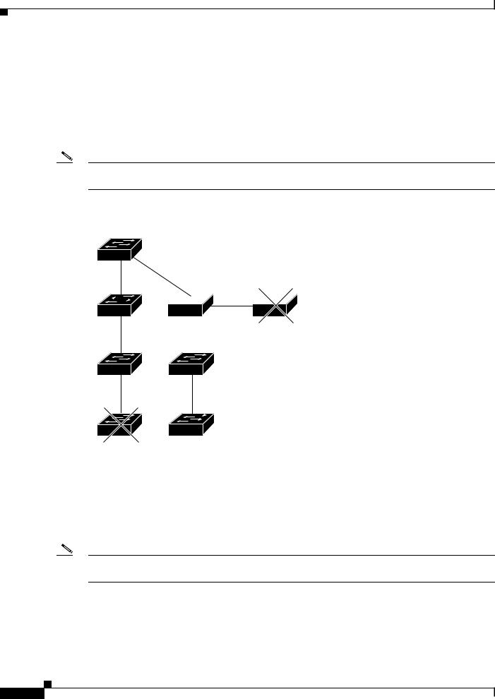
Discovery of Candidates and Members Through CDP Hops
By using CDP, a cluster command switch can discover switches up to seven CDP hops away (the default is three hops) from the edge of the cluster. The last cluster member switches are connected to the cluster and to candidate switches at the edge of the cluster. For example, cluster member switches 9 and 10 in Figure 1 are at the edge of the cluster.
You can set the number of hops that the cluster command switch searches for candidate and cluster member switches by choosing Cluster > Hop Count. When new candidate switches are added to the network, the cluster command switch discovers them and adds them to the list of candidate switches.
Note A switch stack in a cluster equates to a single cluster member switch. There is a restriction specific to adding cluster members through Network Assistant. For more information, see the “Switch Clusters and Switch Stacks” section on page 31.
In Figure 1, the cluster command switch has ports assigned to VLANs 16 and 62. The CDP hop count is three. The cluster command switch discovers switches 11, 12, 13, and 14 because they are within three hops from the edge of the cluster. It does not discover switch 15 because it is four hops from the edge of the cluster.
Cisco IOS Release 12.2(25)SEC
22

Cisco EtherSwitch Service Modules Feature Guide
Information About the Cisco EtherSwitch Service Modules
Figure 1 |
Discovery Through CDP Hops |
Command device
VLAN 16 |
|
VLAN 62 |
||
Member |
|
|
Member |
|
device 8 |
|
|
|
device 10 |
Member |
|
|
Device 12 |
|
device 9 |
|
|
||
|
|
|
||
Device 11 |
|
|
Device 13 Candidate |
|
candidate |
|
|
||
|
|
|||
device |
|
|
devices |
|
|
|
|||
Edge of |
|
cluster |
Device 14 |
|
Device 15
101321
Discovery of Candidates and Members Through Non-CDP-Capable and Noncluster-Capable
Devices
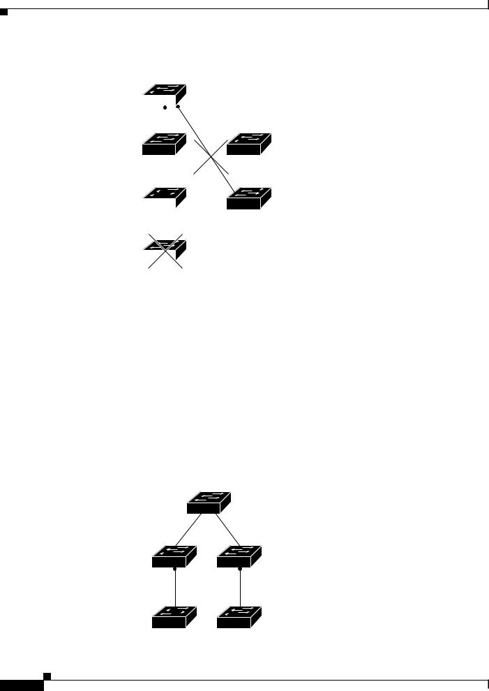
If a cluster command switch is connected to a non-CDP-capable third-party hub (such as a non-Cisco hub), it can discover cluster-enabled devices connected to that third-party hub. However, if the cluster command switch is connected to a noncluster-capable Cisco device, it cannot discover a cluster-enabled device connected beyond the noncluster-capable Cisco device.
Figure 2 shows that the cluster command switch discovers the switch that is connected to a third-party hub. However, the cluster command switch does not discover the switch that is connected to a Catalyst 5000 switch.
Figure 2 |
Discovery Through Non-CDP-Capable and Noncluster-Capable Devices |
Command device
Third-party hub (non-CDP-capable)
Candidate device 
 Catalyst 5000 switch (noncluster-capable)
Candidate device |
89377 |
|
Cisco IOS Release 12.2(25)SEC
23
Cisco EtherSwitch Service Modules Feature Guide
Information About the Cisco EtherSwitch Service Modules
Discovery of Candidates and Members Through Different VLANs
If the cluster command switch is a Cisco EtherSwitch service module, the cluster can have cluster member switches in different VLANs. As cluster member switches, they must be connected through at least one VLAN in common with the cluster command switch. The cluster command switch in Figure 3 has ports assigned to VLANs 9, 16, and 62 and therefore discovers the switches in those VLANs. It does not discover the switch in VLAN 50. It also does not discover the switch in VLAN 16 in the first column because the cluster command switch has no VLAN connectivity to it.
Note For additional considerations about VLANs in switch stacks, see the “Switch Clusters and Switch Stacks” section on page 31.
Figure 3 |
Discovery Through Different VLANs |
Command device
VLAN 62 VLAN trunk 9,16
 VLAN 50
VLAN 62 |
VLAN trunk 9,16 |
|
|
VLAN 16 |
VLAN trunk 4,16 |
101322
Discovery of Candidates and Members Through Different Management VLANs
Cluster command switches can discover and manage cluster member switches in different VLANs and different management VLANs. As cluster member switches, they must be connected through at least one VLAN in common with the cluster command switch. They do not need to be connected to the cluster command switch through their management VLAN. The default management VLAN is VLAN 1.
Note If the switch cluster has a Cisco EtherSwitch service module, Catalyst 3750 switch, or switch stack, that switch or switch stack must be the cluster command switch.
The cluster command switch and standby command switch in Figure 4 have ports assigned to VLANs 9, 16, and 62. The management VLAN on the cluster command switch is VLAN 9. Each cluster command switch discovers the switches in the different management VLANs except these:
•Switches 7 and 10 (switches in management VLAN 4) because they are not connected through a common VLAN (meaning VLANs 62 and 9) with the cluster command switch
Cisco IOS Release 12.2(25)SEC
24

Cisco EtherSwitch Service Modules Feature Guide
Information About the Cisco EtherSwitch Service Modules
•Switch 9 because automatic discovery does not extend beyond a noncandidate device, which is switch 7
Figure 4 |
Discovery Through Different Management VLANs with a Layer 3 Cluster Command |
|
|
Switch |
|
|
Command |
Standby command |
|
device |
device |
VLAN 9
VLAN 16 |
VLAN 62 |
Device 3 (management
VLAN 16) Device 5 
 (management VLAN 62)
VLAN 16 |
VLAN trunk 4, 62 |
Device 7
(management
VLAN 4)
Device 4
(management VLAN 62
VLAN 16)
Device 9 (management VLAN 62)
VLAN 9
Device 6 (management VLAN 9)
VLAN 9
Device 8 (management VLAN 9)
VLAN 4
Device 10 (management VLAN 4)
101323
Discovery of Candidates and Members Through Routed Ports
If the cluster command switch has a routed port (RP) configured, it discovers only candidate and cluster member switches in the same VLAN as the routed port.
The Layer 3 cluster command switch in Figure 5 can discover the switches in VLANs 9 and 62 but not the switch in VLAN 4. If the routed port path between the cluster command switch and cluster member switch 7 is lost, connectivity with cluster member switch 7 is maintained because of the redundant path through VLAN 9.
Cisco IOS Release 12.2(25)SEC
25
Cisco EtherSwitch Service Modules Feature Guide
Information About the Cisco EtherSwitch Service Modules
Figure 5 |
Discovery Through Routed Ports |
|
Command device |
|
VLAN 9 |
|
|
|
|
|
|
|
|
|
RP |
|
|
|
|
|
|
|
|
VLAN 62 |
RP |
|
|
||
|
|
|
|
||
|
|
|
VLAN |
|
|
|
|
|
|
||
|
|
9 |
|
|
|
VLAN 62 |
|
|
|
VLAN 9 |
|
|
|
|
|||
|
|
|
|
|
|
(management |
|
|
|
Member |
|
|
|
|
|||
VLAN 62) |
|
|
|
|
device 7 |
|
|
||||
|
|
|
|
|
|
VLAN 4 |
|
|
|
|
|
|
|
|
101324 |
||
|
|
|
|||
|
|
|
|||
|
|
|
|||
Discovery of Newly Installed Switches in Clusters
To join a cluster, the new, out-of-the-box switch must be connected to the cluster through one of its access ports. An access port (AP) carries the traffic of and belongs to only one VLAN. By default, the new switch and its access ports are assigned to VLAN 1.
When the new switch joins a cluster, its default VLAN changes to the VLAN of the immediately upstream neighbor. The new switch also configures its access port to belong to the VLAN of the immediately upstream neighbor.
The cluster command switch in Figure 6 belongs to VLANs 9 and 16. When new cluster-capable switches join the cluster, the following things happen:
•One cluster-capable switch and its access port are assigned to VLAN 9.
•The other cluster-capable switch and its access port are assigned to management VLAN 16.
Figure 6 |
Discovery of Newly Installed Switches |
Command device
VLAN 9 |
VLAN 16 |
Device A |
Device B |
AP |
AP |
VLAN 9 |
VLAN 16 |
New (out-of-box) |
New (out-of-box) |
candidate device |
candidate device |
101325
Cisco IOS Release 12.2(25)SEC
26

Cisco EtherSwitch Service Modules Feature Guide
Information About the Cisco EtherSwitch Service Modules
HSRP and Standby Cluster Command Switches
The switch supports Hot Standby Router Protocol (HSRP) so that you can configure a group of standby cluster command switches. Because a cluster command switch manages the forwarding of all communication and configuration information to all the cluster member switches, we strongly recommend the following:
•For a cluster command switch stack, a standby cluster command switch is necessary if the entire switch stack fails. However, if only the stack master in the command switch stack fails, the switch stack elects a new stack master and resumes its role as the cluster command switch stack.
•For a cluster command switch that is a standalone switch, configure a standby cluster command switch to take over if the primary cluster command switch fails.
A cluster standby group is a group of command-capable switches that meet the requirements described in the “Standby Command Device Characteristics” section on page 21. Only one cluster standby group can be assigned per cluster.
Note If the switch cluster has a Cisco EtherSwitch service module, Catalyst 3750 switch, or switch stack, that switch or switch stack must be the cluster command switch.
Note The cluster standby group is an HSRP group. Disabling HSRP disables the cluster standby group.
•The switches in the cluster standby group are ranked according to HSRP priorities. The switch with the highest priority in the group is the active cluster command switch (AC). The switch with the next highest priority is the standby cluster command switch (SC). The other switches in the cluster standby group are the passive cluster command switches (PC). If the active cluster command switch and the standby cluster command switch become disabled at the same time, the passive cluster command switch with the highest priority becomes the active cluster command switch. For the limitations to automatic discovery, see the “Automatic Recovery of Cluster Configuration” section on page 29. For information about changing HSRP priority values, see the Catalyst 3750 Switch Software Configuration Guide, Cisco IOS Release 12.2 at http://www.cisco.com/univercd/cc/td/doc/product/lan/cat3750/index.htm. The HSRP standby priority interface configuration commands are the same for changing the priority of cluster standby group members and router-redundancy group members.
Note The HSRP standby hold time interval should be greater than or equal to three times the hello time interval. The default HSRP standby hold time interval is 10 seconds. The default HSRP standby hello time interval is 3 seconds. For more information about the standby hold time and standby hello time intervals, see the Catalyst 3750 Switch Software Configuration Guide, Cisco IOS Release 12.2 at http://www.cisco.com/univercd/cc/td/doc/product/lan/cat3750/index.htm.
These connectivity guidelines ensure automatic discovery of the switch cluster, cluster candidates, connected switch clusters, and neighboring edge devices. These topics also provide more detail about standby cluster command switches:
•Virtual IP Addresses in Clusters, page 28
•Other Considerations for Cluster Standby Groups, page 28
•Automatic Recovery of Cluster Configuration, page 29
Cisco IOS Release 12.2(25)SEC
27
Loading...