


 Loading...
Hardware Installation Guide for the Cisco 4451-X Integrated Services Router
November 21, 2013
Cisco Systems, Inc.
www.cisco.com
Cisco has more than 200 offices worldwide. Addresses, phone numbers, and fax numbers are listed on the Cisco website at www.cisco.com/go/offices.
Text Part Number: OL-27644-01
THE SPECIFICATIONS AND INFORMATION REGARDING THE PRODUCTS IN THIS MANUAL ARE SUBJECT TO CHANGE WITHOUT NOTICE. ALL STATEMENTS, INFORMATION, AND RECOMMENDATIONS IN THIS MANUAL ARE BELIEVED TO BE ACCURATE BUT ARE PRESENTED WITHOUT WARRANTY OF ANY KIND, EXPRESS OR IMPLIED. USERS MUST TAKE FULL RESPONSIBILITY FOR THEIR APPLICATION OF ANY PRODUCTS.
THE SOFTWARE LICENSE AND LIMITED WARRANTY FOR THE ACCOMPANYING PRODUCT ARE SET FORTH IN THE INFORMATION PACKET THAT SHIPPED WITH THE PRODUCT AND ARE INCORPORATED HEREIN BY THIS REFERENCE. IF YOU ARE UNABLE TO LOCATE THE SOFTWARE LICENSE OR LIMITED WARRANTY, CONTACT YOUR CISCO REPRESENTATIVE FOR A COPY.
The following information is for FCC compliance of Class A devices: This equipment has been tested and found to comply with the limits for a Class A digital device, pursuant to part 15 of the FCC rules. These limits are designed to provide reasonable protection against harmful interference when the equipment is operated in a commercial environment. This equipment generates, uses, and can radiate radio-frequency energy and, if not installed and used in accordance with the instruction manual, may cause harmful interference to radio communications. Operation of this equipment in a residential area is likely to cause harmful interference, in which case users will be required to correct the interference at their own expense.
The following information is for FCC compliance of Class B devices: This equipment has been tested and found to comply with the limits for a Class B digital device, pursuant to part 15 of the FCC rules. These limits are designed to provide reasonable protection against harmful interference in a residential installation. This equipment generates, uses and can radiate radio frequency energy and, if not installed and used in accordance with the instructions, may cause harmful interference to radio communications. However, there is no guarantee that interference will not occur in a particular installation. If the equipment causes interference to radio or television reception, which can be determined by turning the equipment off and on, users are encouraged to try to correct the interference by using one or more of the following measures:
•Reorient or relocate the receiving antenna.
•Increase the separation between the equipment and receiver.
•Connect the equipment into an outlet on a circuit different from that to which the receiver is connected.
•Consult the dealer or an experienced radio/TV technician for help.
Modifications to this product not authorized by Cisco could void the FCC approval and negate your authority to operate the product.
The Cisco implementation of TCP header compression is an adaptation of a program developed by the University of California, Berkeley (UCB) as part of UCB’s public domain version of the UNIX operating system. All rights reserved. Copyright © 1981, Regents of the University of California.
NOTWITHSTANDING ANY OTHER WARRANTY HEREIN, ALL DOCUMENT FILES AND SOFTWARE OF THESE SUPPLIERS ARE PROVIDED “AS IS” WITH ALL FAULTS. CISCO AND THE ABOVE-NAMED SUPPLIERS DISCLAIM ALL WARRANTIES, EXPRESSED OR IMPLIED, INCLUDING, WITHOUT LIMITATION, THOSE OF MERCHANTABILITY, FITNESS FOR A PARTICULAR PURPOSE AND NONINFRINGEMENT OR ARISING FROM A COURSE OF DEALING, USAGE, OR TRADE PRACTICE.
IN NO EVENT SHALL CISCO OR ITS SUPPLIERS BE LIABLE FOR ANY INDIRECT, SPECIAL, CONSEQUENTIAL, OR INCIDENTAL DAMAGES, INCLUDING, WITHOUT LIMITATION, LOST PROFITS OR LOSS OR DAMAGE TO DATA ARISING OUT OF THE USE OR INABILITY TO USE THIS MANUAL, EVEN IF CISCO OR ITS SUPPLIERS HAVE BEEN ADVISED OF THE POSSIBILITY OF SUCH DAMAGES.
Cisco and the Cisco logo are trademarks or registered trademarks of Cisco and/or its affiliates in the U.S. and other countries. To view a list of Cisco trademarks, go to this URL: www.cisco.com/go/trademarks. Third-party trademarks mentioned are the property of their respective owners. The use of the word partner does not imply a partnership relationship between Cisco and any other company. (1110R)
Any Internet Protocol (IP) addresses and phone numbers used in this document are not intended to be actual addresses and phone numbers. Any examples, command display output, network topology diagrams, and other figures included in the document are shown for illustrative purposes only. Any use of actual IP addresses or phone numbers in illustrative content is unintentional and coincidental.
Hardware Installation Guide for the Cisco 4451-X Integrated Services Router
© 2013 Cisco Systems, Inc. All rights reserved.

C O N T E N T S
|
Preface ix |
|
|
|
|
|
|
|
|
|
Overview of the Cisco 4451-X Integrated Services Router 1-1 |
||||||||
C H A P T E R 1 |
|||||||||
|
About the Cisco ISR 4451-X |
1-1 |
|
|
|
|
|||
|
Safety Warnings |
1-2 |
|
|
|
|
|
|
|
|
Safety Warnings for Finland, Norway and Sweden |
1-3 |
|||||||
|
Chassis Views |
1-3 |
|
|
|
|
|
|
|
|
Cisco ISR 4451-X Chassis 1-4 |
|
|
|
|||||
|
Platform Summary |
1-7 |
|
|
|
|
|||
|
Locating the Serial Number, PID, VID and CLEI |
1-7 |
|
||||||
|
Labels on Cisco ISR 4451-X |
1-8 |
|
|
|||||
|
For Additional Help Locating Labels on the Router |
1-8 |
|||||||
|
Hardware Features |
1-9 |
|
|
|
|
|
|
|
|
Built-in Interface Ports |
1-9 |
|
|
|
|
|||
|
Front Panel Ethernet Ports |
1-10 |
|
|
|||||
|
Dual Mode GE/SFP Ports |
|
1-10 |
|
|
||||
|
USB Serial Console Port |
1-10 |
|
|
|||||
|
Front Panel PoE+ Ports |
1-10 |
|
|
|||||
|
Internal PoE card |
|
1-11 |
|
|
|
|
||
|
LED Indicators |
1-11 |
|
|
|
|
|
|
|
|
Removable and Interchangeable Modules and Cards |
1-13 |
|||||||
|
Network Interface Modules |
1-15 |
|
|
|||||
|
Cisco UCS E-Series Server Modules |
1-15 |
|
||||||
|
Compact Flash |
1-15 |
|
|
|
|
|||
|
Solid State Drives |
1-15 |
|
|
|
|
|||
|
Packet Voice Digital Signal Processor Modules |
1-16 |
|||||||
|
Memory |
1-16 |
|
|
|
|
|
|
|
|
Power Supplies |
|
1-16 |
|
|
|
|
||
|
Fans, Ventilation, and Airflow |
|
1-17 |
|
|
||||
|
About Slots and Interfaces |
1-17 |
|
|
|
|
|||
|
About Slot, Subslot (Bay), and Port Numbering 1-17 |
||||||||
|
Slot Numbering |
1-19 |
|
|
|
|
|
||
|
About Slot 0 |
1-19 |
|
|
|
|
|||
|
About Slot 1 and 2 |
1-20 |
|
|
|
|
|||
Hardware Installation Guide for the Cisco 4451-X Integrated Services Router
iii

Contents
Additional Slots 1-20 |
|
Subslot/Bay Numbering |
1-20 |
Gigabit Ethernet Management 1-20 |
|
About Fixed Interfaces |
1-20 |
|
Specifications 1-20 |
|
|
|
|
Periodic Inspection and Cleaning |
1-25 |
||
|
Preparing for Router Installation |
|
|
|
C H A P T E R 2 |
2-1 |
|
||
|
Standard Warning Statements |
2-1 |
|
|
|
General Safety Warnings |
2-1 |
|
|
|
Safety Recommendations |
2-5 |
|
|
|
Safety with Electricity |
2-5 |
|
|
|
Preventing Electrostatic Discharge Damage 2-7 |
|||
|
General Site Requirements |
2-7 |
|
|
|
General Precautions |
2-7 |
|
|
|
Site Selection Guidelines |
2-7 |
|
|
|
Site Environmental Requirements 2-8 |
|||
|
Physical Characteristics |
2-9 |
|
|
|
Rack Requirements 2-9 |
|
|
|
|
Router Environmental Requirements |
2-10 |
||
|
Power Guidelines and Requirements |
2-11 |
||
|
Network Cabling Specifications |
2-11 |
|
|
Console and Auxiliary Port Considerations 2-12 |
||
Console Port Connections |
2-12 |
|
Auxiliary Port Connections |
2-13 |
|
Preparing for Network Connections 2-14 |
||
Ethernet Connections 2-14 |
|
|
Required Tools and Equipment for Installation and Maintenance 2-14 |
||
Installation Checklist |
2-16 |
|
Creating a Site Log |
2-17 |
|
C H A P T E R 3 |
Installing and Connecting the Router 3-1 |
|
|
What You Need to Know 3-3 |
|
|
Before You Begin 3-3 |
|
|
Unpacking the Router |
3-4 |
|
Installing the Router |
3-4 |
Rack-Mounting the Chassis 3-5
Attaching Rack-Mount Brackets 3-5
Hardware Installation Guide for the Cisco 4451-X Integrated Services Router
iv

Contents
|
Mounting the Router in a Rack |
3-7 |
|
|
|
|
||||
|
Grounding the Chassis |
3-9 |
|
|
|
|
|
|
||
|
Setting the Chassis on a Desktop |
3-10 |
|
|
|
|
|
|||
|
Chassis Grounding |
3-11 |
|
|
|
|
|
|
|
|
|
Connecting Power |
3-12 |
|
|
|
|
|
|
|
|
|
Connecting to AC Power 3-13 |
|
|
|
|
|
|
|||
|
Connecting to a Console Terminal or Modem |
3-14 |
|
|
|
|||||
|
Connecting to the Serial Port with Microsoft Windows |
3-14 |
||||||||
|
Connecting to the Console Port with Mac OS X 3-15 |
|
|
|||||||
|
Connecting to the Console Port with Linux |
3-16 |
|
|
|
|||||
|
Installing the Cisco Microsoft Windows USB Device Driver |
3-16 |
||||||||
|
Installing the Cisco Microsoft Windows XP USB Driver |
3-17 |
||||||||
|
Installing the Cisco Microsoft Windows 2000 USB Driver |
|
3-17 |
|||||||
|
Installing the Cisco Microsoft Windows Vista USB Driver |
|
3-17 |
|||||||
|
Uninstalling the Cisco Microsoft Windows USB Driver |
3-18 |
|
|
||||||
|
Uninstalling the Cisco Microsoft Windows XP and 2000 USB Driver 3-18 |
|||||||||
|
Uninstalling the Cisco Microsoft Windows Vista USB Driver |
3-19 |
||||||||
|
Connecting to the Auxiliary Port |
3-19 |
|
|
|
|
|
|
||
|
Connecting WAN, LAN, and Voice Interfaces |
3-20 |
|
|
|
|||||
|
Ports and Cabling 3-22 |
|
|
|
|
|
|
|
||
|
Connection Procedures and Precautions |
3-22 |
|
|
|
|||||
|
Initial Configuration |
|
|
|
|
|
|
|
|
|
C H A P T E R 4 |
4-1 |
|
|
|
|
|
|
|
|
|
|
Performing the Initial Configuration on the Router |
4-1 |
|
|
||||||
|
Using Cisco Setup Command Facility 4-1 |
|
|
|
|
|||||
|
Completing the Configuration |
4-4 |
|
|
|
|
|
|||
|
Using Cisco IOS-XE CLI—Manual Configuration |
4-5 |
|
|
||||||
|
Configuring the Router Hostname |
4-6 |
|
|
|
|
||||
|
Configuring the Enable and Enable Secret Passwords |
4-7 |
||||||||
|
Configuring the Console Idle Privileged EXEC Timeout |
4-8 |
||||||||
|
Gigabit Ethernet Management Interface Overview |
4-9 |
|
|
||||||
|
Default Gigabit Ethernet Configuration |
4-10 |
|
|
|
|||||
|
Gigabit Ethernet Port Numbering |
4-10 |
|
|
|
|
||||
|
Configuring Gigabit Ethernet Interfaces |
4-10 |
|
|
|
|||||
|
Configuration Examples |
4-12 |
|
|
|
|
|
|
||
|
Specifying a Default Route or Gateway of Last Resort |
4-12 |
||||||||
|
Configuring IP Routing and IP Protocols |
4-12 |
|
|
|
|||||
|
Default Routes |
4-13 |
|
|
|
|
|
|
|
|
|
Default Network |
4-13 |
|
|
|
|
|
|
|
|
Hardware Installation Guide for the Cisco 4451-X Integrated Services Router
v

Contents
|
Gateway of Last Resort |
4-13 |
|
|
|
|
|||
|
Configuration Examples |
4-15 |
|
|
|
|
|||
|
Configuring Virtual Terminal Lines for Remote Console Access 4-16 |
||||||||
|
Configuration Examples |
4-17 |
|
|
|
|
|||
|
Configuring the Auxiliary Line |
4-17 |
|
|
|||||
|
Verifying Network Connectivity |
4-19 |
|
|
|
|
|||
|
Saving Your Router Configuration |
4-20 |
|
|
|||||
|
Saving Backup Copies of Configuration and System Image 4-20 |
||||||||
|
Configuration Examples |
4-21 |
|
|
|
|
|||
|
Verifying the Initial Configuration |
4-23 |
|
|
|
|
|||
|
ROM Monitor Overview and Basic Procedures |
|
|
||||||
C H A P T E R 5 |
5-1 |
|
|||||||
|
ROM Monitor Overview |
5-1 |
|
|
|
|
|
|
|
|
Entering ROM Monitor Mode |
5-2 |
|
|
|
|
|||
|
Checking the Current ROMmon Version |
5-2 |
|
||||||
|
Commonly Used ROM Monitor Commands |
5-4 |
|
||||||
|
Displaying the Available ROM Monitor Commands |
5-4 |
|||||||
|
Examples |
5-4 |
|
|
|
|
|
|
|
|
Changing the ROM Monitor Prompt |
5-5 |
|
|
|||||
|
Displaying the Configuration Register Setting |
5-5 |
|
||||||
|
Environment Variable Settings |
|
5-5 |
|
|
|
|
||
|
Frequently Used Environmental Variables |
5-6 |
|
||||||
|
Displaying Environment Variable Settings |
5-6 |
|
||||||
|
Entering Environment Variable Settings |
5-7 |
|
||||||
|
Saving Environment Variable Settings |
5-7 |
|
|
|||||
|
Exiting ROM Monitor Mode |
5-7 |
|
|
|
|
|
||
|
Configuration Example |
5-8 |
|
|
|
|
|||
|
Upgrading the ROMmon for a Router |
5-9 |
|
|
|||||
|
Example of Upgrade |
5-9 |
|
|
|
|
|
|
|
|
Installing and Upgrading Internal Modules and FRUs |
|
|||||||
C H A P T E R 6 |
6-1 |
||||||||
|
Safety Warnings |
6-2 |
|
|
|
|
|
|
|
|
Accessing Internal Modules |
6-4 |
|
|
|
|
|||
|
Removing and Replacing the Chassis Cover |
6-4 |
|
||||||
|
Removing the Cover |
6-4 |
|
|
|
|
|||
|
Replacing the Cover |
6-4 |
|
|
|
|
|||
|
Locating Internal and External Slots for Modules |
6-5 |
|
||||||
|
Overview of the SSD Carrier Card NIM (NIM-SSD) 6-6 |
|
|||||||
Hardware Installation Guide for the Cisco 4451-X Integrated Services Router
vi

Contents
Overview 6-7 |
|
|
|
|
|
|
LEDs on the NIM-SSD |
6-8 |
|
|
|
|
|
Solid State Drives (SSD) |
6-10 |
|
|
|
|
|
Installing the SSD Drives into the NIM Carrier Card |
6-12 |
|
||||
Removing the SSD Drives from the NIM-SSD 6-13 |
|
|
||||
Removing and Replacing the Cisco ISR 4451-X NIM-SSD Drives |
6-15 |
|||||
Removing the NIM-SSD from the Router |
6-16 |
|
|
|||
Replacing the NIM-SSD on the Router |
6-18 |
|
|
|||
Installing and Removing DDR DIMMs |
6-18 |
|
|
|
||
Locating and Orienting DIMM |
6-18 |
|
|
|
||
Removing a DIMM |
6-20 |
|
|
|
|
|
Installing a DIMM |
6-21 |
|
|
|
|
|
Installing and Removing NIMs and SMs 6-23 |
|
|
||||
Software Requirement for SMs |
6-24 |
|
|
|
||
Locating an SM or NIM |
6-24 |
|
|
|
|
|
Removing an SM or NIM |
6-24 |
|
|
|
|
|
Installing an SM |
6-24 |
|
|
|
|
|
Verifying SM Installation |
6-25 |
|
|
|
|
|
Installing and Removing the PVDM4 |
6-25 |
|
|
|
||
Tools and Equipment Required During Installation |
6-26 |
|
||||
PVDM4 Location and Orientation |
6-26 |
|
|
|
||
Installing the PVDM4 on the Motherboard of the Cisco ISR 4451-X |
6-27 |
|||||
Removing the PVDM4 from the Motherboard of the Cisco ISR 4451-X 6-28
Installing the PVDM4 on the Cisco Fourth-Generation T1/E1 Voice and WAN NIM in the Cisco ISR 4451-X
Removing the PVDM4 from the Cisco Fourth-Generation T1/E1 Voice and WAN Network Interface Module in the Cisco ISR 4451-X
Removing and Replacing the USB Flash Token Memory Stick
Replacing Power Supplies and Redundant Power Supplies
Replacing the Cisco ISR 4451-X Power Supply 6-31
Replacing the Power Supply on the Cisco ISR 4451-Xs 6-33
Inserting PoE Supply in an Ethernet Switch Network Module
Cisco ISR 4451-X Power and RPS Error Messages
Replacing a Fan Tray 6-34
Before Hot-Swapping a Fan Tray 6-34
Replacing the Cisco ISR 4451-X Fan Tray 6-34
Removing and Installing a CompactFlash Memory Card
Preventing Electrostatic Discharge Damage
Removing a CompactFlash Memory Card
Hardware Installation Guide for the Cisco 4451-X Integrated Services Router
vii

Contents
Installing a CompactFlash Memory Card 6-37 |
|
Installing SFP Modules 6-38 |
|
Laser Safety Guidelines |
6-40 |
Removing SFP Modules |
6-40 |
|
Removing, Replacing, and Installing an Internal PoE Card |
6-41 |
|
|
Online Insertion and Removal (OIR) and Hot-Swapping |
|
|
C H A P T E R 7 |
7-1 |
||
|
OIR Procedures 7-2 |
|
|
|
Removing a Module |
7-2 |
|
|
Inserting a Data or Voice Module 7-2 |
|
|
|
Hot-Swapping Procedures |
7-2 |
|
Hardware Installation Guide for the Cisco 4451-X Integrated Services Router
viii

Preface
This preface describes the objectives, audience, organization and conventions of this guide, and the references that accompany this document set. The following sections are provided:
•Objectives, page ix
•Audience, page ix
•Organization, page x
•Conventions, page xi
•Related Documentation, page xvii
•Searching for Cisco Documents, page xviii
•Obtaining Documentation and Submitting a Service Request, page xviii
Objectives
This guide explains how to install, connect, and perform initial configurations for the Cisco 4451-X Integrated Services Router (ISR).
Note For warranty, service, and support information, see the “Cisco Warranty Terms” section in the
Pointer Card for the Cisco 4451-X Integrated Services Router document that was shipped with your router.
Audience
This guide is intended for Cisco equipment providers and service persons who are technically knowledgeable and familiar with Cisco routers and Cisco IOS software and features. They would understand how to install, configure, and maintain the router, and they should be familiar with electronic circuitry and wiring practices, and have experience as an electronic or electromechanical technician. This guide identifies certain procedures that should be performed only by trained and qualified personnel.
Hardware Installation Guide for the Cisco 4451-X Integrated Services Router
|
OL-27644-01 |
ix |
|

Organization
This guide includes the following chapters:
Chapter |
Title |
Description |
|
|
|
1 |
Overview of the Cisco 4451-X |
Describes the router chassis views, information |
|
Integrated Services Router |
for locating the serial number, PID1, and UDI2. |
|
|
Also includes general hardware features, slot, |
|
|
port, and interface information; and LED |
|
|
indicators. |
|
|
|
2 |
Preparing for Router Installation |
Describes site requirements and the equipment |
|
|
needed to install the router. |
|
|
|
3 |
Installing and Connecting the Router |
Describes how to install and connect the router to |
|
|
LAN, WAN, and Voice networks. |
|
|
|
4 |
Initial Configuration |
Describes how to power up the router and |
|
|
perform the initial configuration. |
|
|
|
5 |
ROM Monitor Overview and Basic |
Provides an overview of ROM Monitor concepts |
|
Procedures |
and operations. |
|
|
|
6 |
Installing and Upgrading Internal |
Describes how to install and upgrade internal |
|
Modules and FRUs |
modules and field replaceable units3 on the |
|
|
router. |
|
|
|
7 |
Online Insertion and Removal (OIR) |
Describes how to remove and replace data and |
|
and Hot-Swapping |
modules using the online insertion and removal4 |
|
|
procedure. |
|
|
|
1.PID = Product ID
2.UDI = Universal Device Identifier
3.FRU = Field Replaceable Unit
4.OIR = Online Insertion and Removal
Hardware Installation Guide for the Cisco 4451-X Integrated Services Router
|
x |
OL-27644-01 |
|
|
|
Conventions
This document uses the following conventions:
Convention |
Indication |
|
|
|
|
bold font |
Commands and keywords and user-entered text appear in bold font. |
|
|
|
|
italic font |
Document titles, new or emphasized terms, and arguments for which you supply |
|
|
|
values are in italic font. |
|
|
|
[ |
] |
Elements in square brackets are optional. |
|
|
|
{x | y | z } |
Required alternative keywords are grouped in braces and separated by |
|
|
|
vertical bars. |
|
|
|
[ x | y | z ] |
Optional alternative keywords are grouped in brackets and separated by |
|
|
|
vertical bars. |
|
|
|
string |
A nonquoted set of characters. Do not use quotation marks around the string or |
|
|
|
the string will include the quotation marks. |
|
|
|
courier font |
Terminal sessions and information the system displays appear in courier font. |
|
|
|
|
< |
> |
Nonprinting characters such as passwords are in angle brackets. |
|
|
|
[ |
] |
Default responses to system prompts are in square brackets. |
|
|
|
!, # |
An exclamation point (!) or a pound sign (#) at the beginning of a line of code |
|
|
|
indicates a comment line. |
|
|
|
Note Means reader take note.
Tip Means the following information will help you solve a problem.
Caution Means reader be careful. In this situation, you might perform an action that could result in equipment damage or loss of data.
Timesaver Means the described action saves time. You can save time by performing the action described in the paragraph.
Hardware Installation Guide for the Cisco 4451-X Integrated Services Router
|
OL-27644-01 |
xi |
|

Warning IMPORTANT SAFETY INSTRUCTIONS
This warning symbol means danger. You are in a situation that could cause bodily injury. Before you work on any equipment, be aware of the hazards involved with electrical circuitry and be familiar with standard practices for preventing accidents. Use the statement number provided at the end of each warning to locate its translation in the translated safety warnings that accompanied this device. Statement 1071
SAVE THESE INSTRUCTIONS
Waarschuwing BELANGRIJKE VEILIGHEIDSINSTRUCTIES
Dit waarschuwingssymbool betekent gevaar. U verkeert in een situatie die lichamelijk letsel kan veroorzaken. Voordat u aan enige apparatuur gaat werken, dient u zich bewust te zijn van de bij elektrische schakelingen betrokken risico's en dient u op de hoogte te zijn van de standaard praktijken om ongelukken te voorkomen. Gebruik het nummer van de verklaring onderaan de waarschuwing als u een vertaling van de waarschuwing die bij het apparaat wordt geleverd, wilt raadplegen.
BEWAAR DEZE INSTRUCTIES
Varoitus TÄRKEITÄ TURVALLISUUSOHJEITA
Tämä varoitusmerkki merkitsee vaaraa. Tilanne voi aiheuttaa ruumiillisia vammoja. Ennen kuin käsittelet laitteistoa, huomioi sähköpiirien käsittelemiseen liittyvät riskit ja tutustu onnettomuuksien yleisiin ehkäisytapoihin. Turvallisuusvaroitusten käännökset löytyvät laitteen mukana toimitettujen käännettyjen turvallisuusvaroitusten joukosta varoitusten lopussa näkyvien lausuntonumeroiden avulla.
SÄILYTÄ NÄMÄ OHJEET
Attention IMPORTANTES INFORMATIONS DE SÉCURITÉ
Ce symbole d'avertissement indique un danger. Vous vous trouvez dans une situation pouvant entraîner des blessures ou des dommages corporels. Avant de travailler sur un équipement, soyez conscient des dangers liés aux circuits électriques et familiarisez-vous avec les procédures couramment utilisées pour éviter les accidents. Pour prendre connaissance des traductions des avertissements figurant dans les consignes de sécurité traduites qui accompagnent cet appareil, référez-vous au numéro de l'instruction situé à la fin de chaque avertissement.
CONSERVEZ CES INFORMATIONS
Warnung WICHTIGE SICHERHEITSHINWEISE
Dieses Warnsymbol bedeutet Gefahr. Sie befinden sich in einer Situation, die zu Verletzungen führen kann. Machen Sie sich vor der Arbeit mit Geräten mit den Gefahren elektrischer Schaltungen und den üblichen Verfahren zur Vorbeugung vor Unfällen vertraut. Suchen Sie mit der am Ende jeder Warnung angegebenen Anweisungsnummer nach der jeweiligen Übersetzung in den übersetzten Sicherheitshinweisen, die zusammen mit diesem Gerät ausgeliefert wurden.
BEWAHREN SIE DIESE HINWEISE GUT AUF.
Hardware Installation Guide for the Cisco 4451-X Integrated Services Router
|
xii |
OL-27644-01 |
|
|
|

Avvertenza IMPORTANTI ISTRUZIONI SULLA SICUREZZA
Questo simbolo di avvertenza indica un pericolo. La situazione potrebbe causare infortuni alle persone. Prima di intervenire su qualsiasi apparecchiatura, occorre essere al corrente dei pericoli relativi ai circuiti elettrici e conoscere le procedure standard per la prevenzione di incidenti. Utilizzare il numero di istruzione presente alla fine di ciascuna avvertenza per individuare le traduzioni delle avvertenze riportate in questo documento.
CONSERVARE QUESTE ISTRUZIONI
Advarsel VIKTIGE SIKKERHETSINSTRUKSJONER
Dette advarselssymbolet betyr fare. Du er i en situasjon som kan føre til skade på person. Før du begynner å arbeide med noe av utstyret, må du være oppmerksom på farene forbundet med elektriske kretser, og kjenne til standardprosedyrer for å forhindre ulykker. Bruk nummeret i slutten av hver advarsel for å finne oversettelsen i de oversatte sikkerhetsadvarslene som fulgte med denne enheten.
TA VARE PÅ DISSE INSTRUKSJONENE
Aviso INSTRUÇÕES IMPORTANTES DE SEGURANÇA
Este símbolo de aviso significa perigo. Você está em uma situação que poderá ser causadora de lesões corporais. Antes de iniciar a utilização de qualquer equipamento, tenha conhecimento dos perigos envolvidos no manuseio de circuitos elétricos e familiarize-se com as práticas habituais de prevenção de acidentes. Utilize o número da instrução fornecido ao final de cada aviso para localizar sua tradução nos avisos de segurança traduzidos que acompanham este dispositivo.
GUARDE ESTAS INSTRUÇÕES
¡Advertencia! INSTRUCCIONES IMPORTANTES DE SEGURIDAD
Este símbolo de aviso indica peligro. Existe riesgo para su integridad física. Antes de manipular cualquier equipo, considere los riesgos de la corriente eléctrica y familiarícese con los procedimientos estándar de prevención de accidentes. Al final de cada advertencia encontrará el número que le ayudará a encontrar el texto traducido en el apartado de traducciones que acompaña a este dispositivo.
GUARDE ESTAS INSTRUCCIONES
Varning! VIKTIGA SÄKERHETSANVISNINGAR
Denna varningssignal signalerar fara. Du befinner dig i en situation som kan leda till personskada. Innan du utför arbete på någon utrustning måste du vara medveten om farorna med elkretsar och känna till vanliga förfaranden för att förebygga olyckor. Använd det nummer som finns i slutet av varje varning för att hitta dess översättning i de översatta säkerhetsvarningar som medföljer denna anordning.
SPARA DESSA ANVISNINGAR
Hardware Installation Guide for the Cisco 4451-X Integrated Services Router
|
OL-27644-01 |
xiii |
|
Hardware Installation Guide for the Cisco 4451-X Integrated Services Router
|
xiv |
OL-27644-01 |
|
|
|
Aviso INSTRUÇÕES IMPORTANTES DE SEGURANÇA
Este símbolo de aviso significa perigo. Você se encontra em uma situação em que há risco de lesões corporais. Antes de trabalhar com qualquer equipamento, esteja ciente dos riscos que envolvem os circuitos elétricos e familiarize-se com as práticas padrão de prevenção de acidentes. Use o número da declaração fornecido ao final de cada aviso para localizar sua tradução nos avisos de segurança traduzidos que acompanham o dispositivo.
GUARDE ESTAS INSTRUÇÕES
Advarsel VIGTIGE SIKKERHEDSANVISNINGER
Dette advarselssymbol betyder fare. Du befinder dig i en situation med risiko for legemesbeskadigelse. Før du begynder arbejde på udstyr, skal du være opmærksom på de involverede risici, der er ved elektriske kredsløb, og du skal sætte dig ind i standardprocedurer til undgåelse af ulykker. Brug erklæringsnummeret efter hver advarsel for at finde oversættelsen i de oversatte advarsler, der fulgte med denne enhed.
GEM DISSE ANVISNINGER
Hardware Installation Guide for the Cisco 4451-X Integrated Services Router
|
OL-27644-01 |
xv |
|

Hardware Installation Guide for the Cisco 4451-X Integrated Services Router
|
xvi |
OL-27644-01 |
|
|
|

Warning When installing the product, please use the provided or designated connection cables/power cables/AC adaptors. Using any other cables/adaptors could cause a malfunction or a fire. Electrical Appliance and Material Safety Law prohibits the use of UL-certified cables (that have the “UL” shown on the code) for any other electrical devices than products designated by CISCO. The use of cables that are certified by Electrical Appliance and Material Safety Law (that have “PSE” shown on the code) is not limited to CISCO-designated products. Statement 371.
Warning There is the danger of explosion if the battery is replaced incorrectly. Replace the battery only with the same or equivalent type recommended by the manufacturer. Dispose of used batteries according to the manufacturer’s instructions. Statement 1015
Warning Do not use this product near water; for example, near a bath tub, wash bowl, kitchen sink or laundry tub, in a wet basement, or near a swimming pool. Statement 1035
Warning Never install telephone jacks in wet locations unless the jack is specifically designed for wet locations. Statement 1036
Warning Never touch uninsulated telephone wires or terminals unless the telephone line has been disconnected at the network interface. Statement 1037
Related Documentation
For a list of all related release and supported module documentation, see the Documentation Roadmap for the Cisco 4451-X Integrated Services Routers at the following URL: http://www.cisco.com/en/US/docs/routers/access/4400/roadmap/isr4400roadmap.html
Hardware Installation Guide for the Cisco 4451-X Integrated Services Router
|
OL-27644-01 |
xvii |
|

Searching for Cisco Documents
To search an HTML document using a web browser, press Ctrl-F (Windows) or Cmd-F (Apple). In most browsers, the option to search whole words only, invoke case sensitivity, or search forward and backward is also available.
To search a PDF document in Adobe Reader, use the basic Find toolbar (Ctrl-F) or the Full Reader Search window (Shift-Ctrl-F). Use the Find toolbar to find words or phrases within a specific document. Use the Full Reader Search window to search multiple PDF files simultaneously and to change case sensitivity and other options. The Adobe Reader online help has more information about how to search PDF documents.
Obtaining Documentation and Submitting a Service Request
For information on obtaining documentation, submitting a service request, and gathering additional information, see What’s New in Cisco Product Documentation at: http://www.cisco.com/en/US/docs/general/whatsnew/whatsnew.html.
Subscribe to What’s New in Cisco Product Documentation, which lists all new and revised Cisco technical documentation, as an RSS feed and deliver content directly to your desktop using a reader application. The RSS feeds are a free service
Hardware Installation Guide for the Cisco 4451-X Integrated Services Router
|
xviii |
OL-27644-01 |
|
|
|

C H A P T E R 1
Overview of the Cisco 4451-X Integrated Services
Router
About the Cisco ISR 4451-X
The Cisco 4451-X Integrated Services Router (ISR) is a modular router with LAN and WAN connectivity and supports several interface modules, including Cisco Service Modules (SMs), or Enhanced Service Modules (SM-X), and Network Interface Modules (NIMs). The router has slots that support the interface modules and modular Solid State Drives (SSDs).
The Cisco ISR 4451-Xs target the following applications:
•Enterprise applications—Intended as the mid-size aggregation and gateway router typically residing in a regional or large branch office:
–WAN aggregation at Cisco Enterprise core
–Internet gateway
–Branch or regional office aggregation
–Remote access aggregation
•Service provider applications—Intended for high-end Enterprise Branch environments.:
–High-end customer premises equipment (CPE) for business-quality Internet access
–Service provider leased line aggregation
–Provider edge (PE) and high-end customer edge (CE) for Layer 2 VPN or Layer 3 VPN services
–Broadband aggregation—PPPoE/PPPoA aggregation and Service Selection Gateway (SSG)
–Low-end Ethernet aggregation
The Cisco ISR 4451-Xs provide the following capabilities:
•Two single-wide SM slots that may be combined into one double wide SM slot.
•Three single-wide NIM slots that may combined into one double wide (NIM1 and NIM2) and one single wide NIM slot (NIM3). The slots can also support a modular or optional SSD.
•NIM3 slot also functions as a special hard drive carrier slot.
•1 10/100/1000 RJ-45 Ethernet port for system managements (labeled "GE 0" with “MGMT” on the left of the connector)
•2 USB 2 Type A host ports
•1 USB mini-TypeB Console (placed next to the RJ45 Console port)
Hardware Installation Guide for the Cisco 4451-X Integrated Services Router
|
OL-27644-01 |
1-1 |
|
|
|

Chapter 1 Overview of the Cisco 4451-X Integrated Services Router
Safety Warnings
•1 RJ45 Console
•1 RJ45 AUX port with full modem control signals
•4 10/100/1000 RJ-45 Ethernet ports (labeled GE 0/0/0, 0/0/1, 0/0/2, and 0/0/3)
•4 100/1000 SFP Ethernet ports (labeled SFP 0/0/0, 0/0/1, 0/0/2, and 0/0/3)
•LEDs for Ethernet and console status
•LEDs for SATA hard disk drive activity and status (available on certain models)
•Two DDR3 240 pin Control Plane DIMM slots which can be replaced
•One DDR3 240 pin Data Plane DIMM slot which can be replaced
•One compact flash slot, which is serviceable when the fan tray is removed
•One 30W PoE daughter card for two of the front Gigabit Ethernet ports which can be replaced (labeled GE 0/0/0 and 0/0/1)
•One Packet Voice Digital Signal Processor Module (PVDM4) providing IP Voice and video capability
•Environment monitoring
•Field replaceable fan tray
•Dual redundant power supply units (PSUs) and PoE PSU.
This chapter contains the following sections:
•Safety Warnings, page 1-2
•Chassis Views, page 1-3
•Locating the Serial Number, PID, VID and CLEI, page 1-7
•Hardware Features, page 1-9
•About Slots and Interfaces, page 1-17
•Specifications, page 1-20
•Periodic Inspection and Cleaning, page 1-25
Safety Warnings
Warning IMPORTANT SAFETY INSTRUCTIONS
This warning symbol means danger. You are in a situation that could cause bodily injury. Before you work on any equipment, be aware of the hazards involved with electrical circuitry and be familiar with standard practices for preventing accidents. Use the statement number provided at the end of each warning to locate its translation in the translated safety warnings that accompanied this device.
Statement 1071
SAVE THESE INSTRUCTIONS
Hardware Installation Guide for the Cisco 4451-X Integrated Services Router
|
OL-27644-01 |
1-2 |
|
|
|
Chapter 1 Overview of the Cisco 4451-X Integrated Services Router
Chassis Views
Warning Ultimate disposal of this product should be handled according to all national laws and regulations.
Statement 1040
Warning Only trained and qualified personnel should be allowed to install, replace, or service this equipment.
Statement 1030
Safety Warnings for Finland, Norway and Sweden
Warning statement 1017 applies to the countries of Finland, Norway, and Sweden.
Warning This unit is intended for installation in restricted access areas. A restricted access area can be accessed only through the use of a special tool, lock and key, or other means of security.
Statement 1017
Chassis Views
This section contains views of the front and back panels of the Cisco ISR 4451-Xs, showing locations of the power and signal interfaces, module slots, status indicators, and chassis identification labels.
Note The Cisco ISR 4451-Xs support the following slot types:
-Network Interface Modules (NIMs)
-Service modules (SMs, like SM-X-1T3/E3)
-Integrated Services Card (ISC slots for PVDM4s)
-E-Series Server Modules
-Solid State Drives (SSDs).
Hardware Installation Guide for the Cisco 4451-X Integrated Services Router
|
OL-27644-01 |
1-3 |
|
|
|
Chapter 1 Overview of the Cisco 4451-X Integrated Services Router
Chassis Views
Cisco ISR 4451-X Chassis
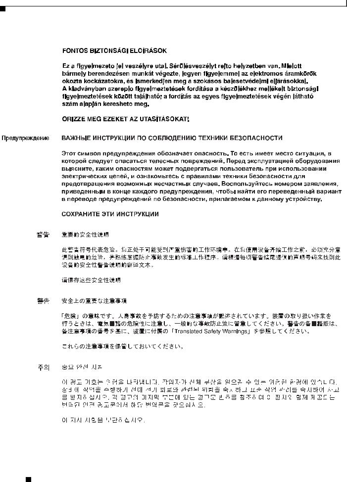
Figure 1-1 on page 1-4— Bezel view with one PSU
Figure 1-2 on page 1-5— Bezel view with two PSUs
Figure 1-3 on page 1-5— Back panel slots and ports
Figure 1-4 on page 1-6—Bezel side LEDs
Figure 1-1 |
Bezel View of the Cisco ISR 4451-X with one Power Supply Unit |
|
|
|
|||
|
|
|
1 |
|
|
2 |
3 |
|
|
|
|
Cisco |
Series |
||
|
|
|
|
PSU1 |
PSU2 |
FLASH TEMP PWR |
|
|
|
|
|
|
|
POE |
|
|
|
|
|
POE1 |
POE2 |
BOOST VM |
FAN STAT |
|
|
|
|
|
|
|
285694 |
|
|
5 |
|
|
|
|
4 |
1 |
Router fan tray |
2 |
LEDs |
|
|
|
|
3 |
Router power On/Off switch |
4 |
Power supply unit (PSU) |
|
|
|
|
5 |
Optional power supply unit |
|
|
|
|
|
|
Hardware Installation Guide for the Cisco 4451-X Integrated Services Router
|
OL-27644-01 |
1-4 |
|
|
|
Chapter 1 Overview of the Cisco 4451-X Integrated Services Router
Chassis Views
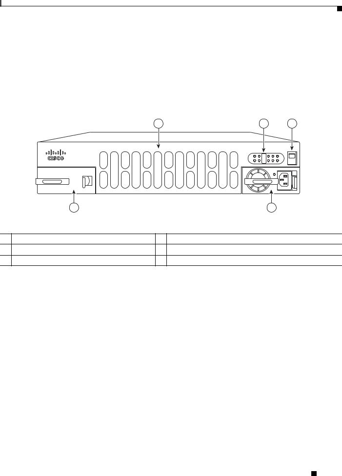
Figure 1-2 |
Bezel side of the Cisco ISR 4451-X with two PSUs |
|
|
|
||
|
|
1 |
|
|
2 |
3 |
|
|
|
Cisco 4400 Series |
|||
|
|
|
PSU1 |
PSU2 |
INT FLASH |
TEMP PWR |
|
|
|
|
|
POE |
|
|
|
|
POE1 |
POE2 |
BOOST VM |
FAN STAT |
|
|
|
|
|
|
285695 |
|
|
5 |
|
|
4 |
|
1 |
Router fan tray |
2 LEDs |
|
|
|
|
3 |
Router power On/Off switch |
4 AC power supply unit (P1) |
|
|
|
|
5 |
AC power supply unit (P0) |
|
|
|
|
|
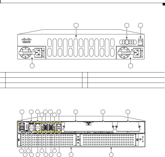
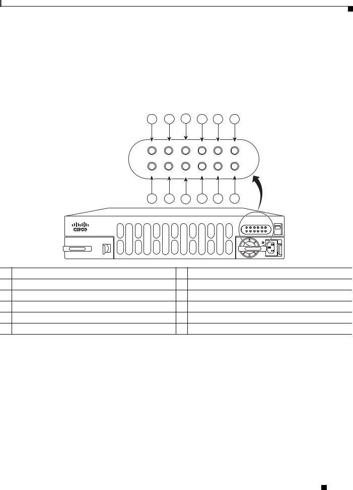
Figure 1-3 Back Panel (I/O Side) Slots and Connectors on the Cisco ISR 4451-X
1 |
2 |
3 |
5 |
6 |
8 |
9 |
10 |
11 |
|
|
|
|
4 |
|
7 |
|
|
|
|
2 |
|
|
|
|
|
|
|
1 |
285698 |
|
|
|
|
|
|
|
|
|
|
23 |
21 |
|
18 |
|
15 |
|
|
|
|
22 |
20 |
19 |
17 |
16 |
14 |
13 |
|
12 |
|
1 |
GE 0 management port |
|
2 |
Auxiliary port |
|
|||
|
|
|
|
|
|
|||
3 |
RJ45 Gigabit Ethernet port (GE 0/0/0) |
|
4 |
LEDs for the GE 0/0/0 interface (See Table 1-1 for |
||||
|
|
|
|
|
detailed LED information) |
|||
|
|
|
|
|
|
|||
5 |
SFP Gigabit Ethernet port (GE 0/0/0) |
|
6 |
SFP Gigabit Ethernet port (GE 0/0/2) |
||||
|
|
|
|
|
|
|||
7 |
LEDs for the GE 0/0/2 interface |
|
8 |
RJ45 Gigabit Ethernet port (GE 0/0/2) |
||||
|
|
|
|
|
|
|||
9 |
NIM slot 1 |
|
10 |
NIM slot 2 |
||||
|
|
|
|
|
|
|||
11 |
NIM slot 3 (Optional Modular SSD Slot) |
|
12 |
Enhanced Service Module (SM-X) 2 |
||||
|
|
|
|
|
|
|||
13 |
Enhanced Service Module (SM-X) 1 |
|
14 |
RJ45 Gigabit Ethernet port GE 0/0/3 |
||||
|
|
|
|
|
|
|||
15 |
LEDs for the GE 0/0/3 interface |
|
16 |
SFP Gigabit Ethernet GE 0/0/3 |
||||
|
|
|
|
|
|
|
|
|
|
|
|
Hardware Installation Guide for the Cisco 4451-X Integrated Services Router |
|
|
|||
|
|
|
|
|||||
|
|
|
|
|
|
|
|
|
|
OL-27644-01 |
|
|
|
|
1-5 |
|
|
|
|
|
|
|
|
|||
Chapter 1 Overview of the Cisco 4451-X Integrated Services Router
Chassis Views
17 |
SFP Gigabit Ethernet GE 0/0/1 |
18 |
LEDs for the GE 0/0/1 interface |
|
|
|
|
19 |
RJ45 Gigabit Ethernet port GE 0/0/1 |
20 |
Serial Console Port |
|
|
|
|
21 |
Console port USB 0 and USB 1 |
|
|
|
|
|
|
Figure 1-4 |
Bezel Side LEDS of the Single PSU Cisco ISR 4451-X Model |
|
|
|
|||||
|
|
1 |
2 |
3 |
4 |
5 |
6 |
|
|
|
|
PSU0 |
PSU1 |
INT |
FLASH |
TEMP |
PWR |
|
|
|
|
|
|
POE |
|
|
|
|
|
|
|
POE0 |
POE1 BOOST |
VM |
FAN |
STAT |
|
|
|
|
|
12 |
11 |
10 |
9 |
8 |
7 |
|
|
|
|
|
|
|
|
|
Cisco 4400 Series |
||
|
|
|
|
|
|
|
PSU10 |
PSU21 |
IINT FLASH TEMP PWR |
|
|
|
|
|
|
|
|
|
POEPOE |
|
|
|
|
|
|
|
POE10 |
POE2POE1 |
BOOST VM FAN STAT |
|
|
|
|
|
|
|
|
|
285696 |
1 |
PSU0: Power supply unit 1 |
2 |
PSU1: Power supply unit 2 |
||||||
3 |
GE POE: Internal PoE daughter card status |
4 |
FLASH: Compact flash status |
||||||
5 |
TEMP: Temperature status |
6 |
PWR: Power |
|
|
|
|||
7 |
STAT: System status |
8 |
FAN: Fan status |
|
|
||||
9 |
ISC: Integrated Services Card status |
10 POE BOOST: Power over Ethernet boost mode |
|||||||
11 |
POE 1: Power over Ethernet 2 status |
12 POE 0: Power over Ethernet 1 status |
|||||||
Hardware Installation Guide for the Cisco 4451-X Integrated Services Router
|
OL-27644-01 |
1-6 |
|
|
|
Chapter 1 Overview of the Cisco 4451-X Integrated Services Router
Locating the Serial Number, PID, VID and CLEI
Platform Summary
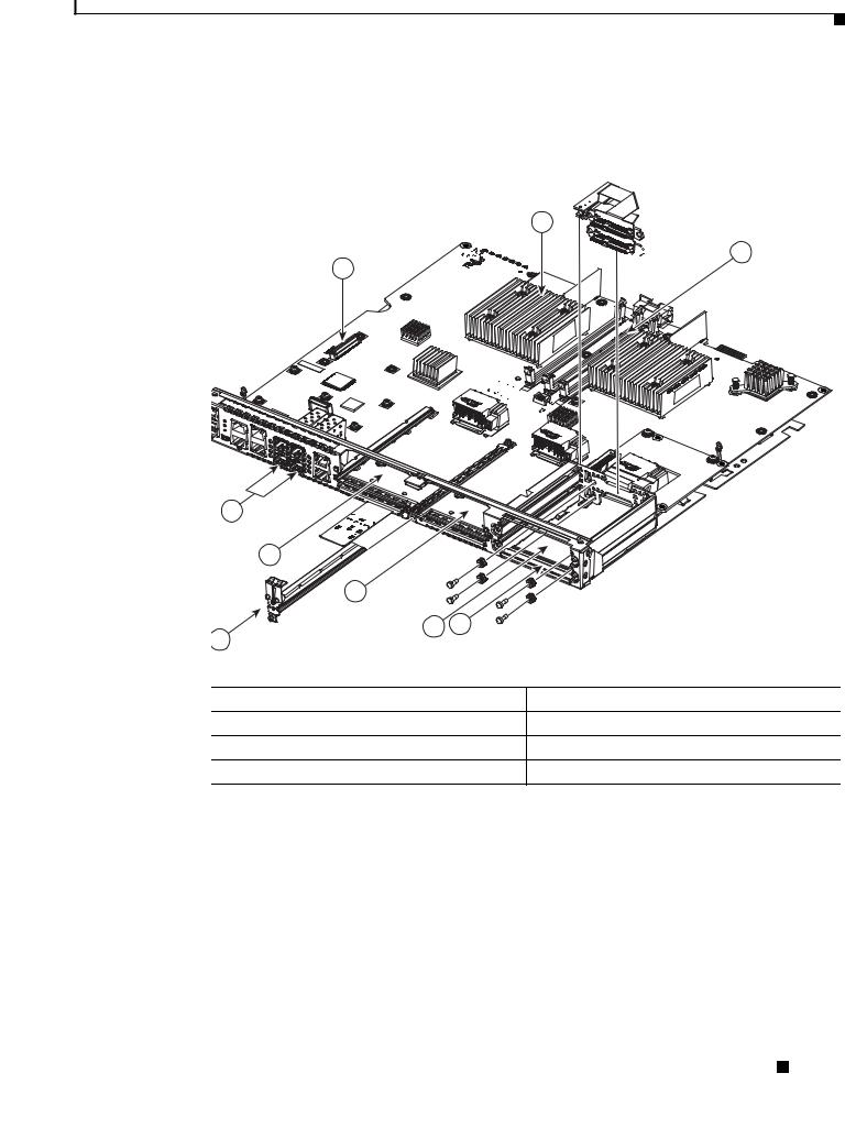
Figure 1-5 shows an internal view of the Cisco ISR 4451-X with all the parts and module location.
Figure 1-5 Platform Summary of the Cisco ISR 4451-X
2


 3 1
3 1 


285699
|
9 |
|
|
|
|
8 |
|
|
|
|
6 |
|
|
|
7 |
5 |
4 |
|
|
|
|
|
|
|
1. |
ISC slot |
|
2. |
CPU |
3. |
DIMM |
|
4. |
Modular HDD Slot (Factory-configured) |
5. |
Modular HDD slot (Factory-configured) |
6. |
NIM 2 (single-wide) |
|
7. |
NIM slot divider |
|
8. |
NIM 1 (single-wide) |
Locating the Serial Number, PID, VID and CLEI
Software License
To obtain a software license, you need a product authorization key (PAK) and the unique device identifier (UDI) of the device where the license will be installed.
The serial number (SN), product ID (PID), version ID (VID), and Common Language Equipment Identifier (CLEI) are printed on a label on the back of the router or on a label tray located on the router chassis or motherboard. The UDI can be viewed using the show license udi command in privileged Exec
Hardware Installation Guide for the Cisco 4451-X Integrated Services Router
|
OL-27644-01 |
1-7 |
|
|
|
Chapter 1 Overview of the Cisco 4451-X Integrated Services Router
Locating the Serial Number, PID, VID and CLEI
mode in Cisco Internet Operating System (IOS) software. For additional information on the UDI or how to obtain a PAK, see the Cisco Software Activation on Integrated Services Routers document on Cisco.com.
The UDI has two main components:
•Product ID (PID)
•Serial number (SN)
Labels on Cisco ISR 4451-X
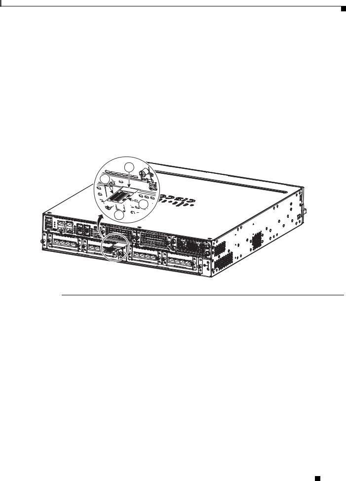
Figure 1-6 shows the location of the labels on the Cisco ISR 4451-Xs.
Figure 1-6 Label Location on the Cisco ISR 4451-X
2


 1
1


 3
3


 4
4


302982
Label |
Description |
1 |
Product ID |
|
|
2 |
Serial Number |
|
|
3 |
PID/VID |
|
|
4 |
CLEI |
|
|
For Additional Help Locating Labels on the Router
Use the Cisco Product Identification (CPI) tool to find labels on the router. It provides detailed illustrations and descriptions of where the labels are located on Cisco products. It includes the following features:
•A search option that allows browsing for models by using a tree-structured product hierarchy
•A search field on the final results page that makes it easier to look up multiple products
•End-of-sale products clearly identified in results lists
The tool streamlines the process of locating serial number labels and identifying products. Serial number information expedites the entitlement process and is important for access to support services.
Hardware Installation Guide for the Cisco 4451-X Integrated Services Router
|
OL-27644-01 |
1-8 |
|
|
|
Chapter 1 Overview of the Cisco 4451-X Integrated Services Router
Hardware Features
The Cisco Product Identification tool can be accessed at the following URL:
http://tools.cisco.com/Support/CPI/index.do
Hardware Features
This section describes the hardware features in the Cisco ISR 4451-X.
•Built-in Interface Ports, page 1-9
•LED Indicators, page 1-11
•Removable and Interchangeable Modules and Cards, page 1-13
•Fans, Ventilation, and Airflow, page 1-17
•About Slots and Interfaces, page 1-17
Built-in Interface Ports
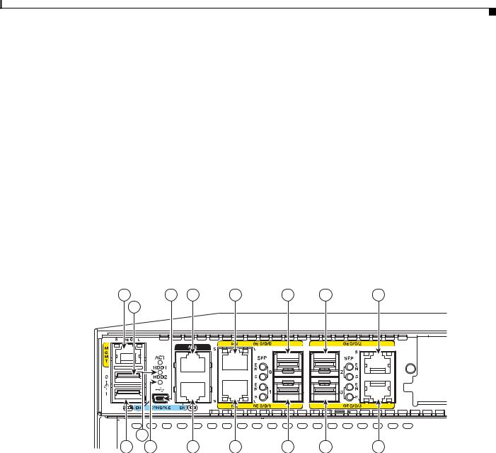
Figure 1-7 Ports on the Cisco ISR 4451-X
1 |
|
3 |
4 |
5 |
6 |
7 |
8 |
|
2 |
|
|
|
|
|
|
|
|
|
|
|
|
|
L |
|
|
|
|
|
|
|
L |
|
15 |
|
|
|
|
|
|
16 |
14 |
|
13 |
12 |
11 |
10 |
9 |
1 |
Gigabit Ethernet management port |
2 |
USB port 0 |
|
|
|
|
3 |
USB console |
4 |
Auxiliary port |
|
|
|
|
5 |
Gigabit Ethernet port 0 |
6 |
Small-form-factor pluggable (SFP) 0 |
|
|
|
|
7 |
SFP 2 |
8 |
Gigabit Ethernet port 2 |
|
|
|
|
9 |
Gigabit Ethernet port 3 |
10 |
SFP 3 |
|
|
|
|
11 |
SFP 1 |
12 |
Gigabit Ethernet port 1 |
|
|
|
|
13 |
Serial Console port |
14 |
HDD LEDs |
|
|
|
|
15 |
HDD LEDs |
16 |
USB port 1 |
|
|
|
|
|
|
The Cisco ISR 4451-Xs have four 10/100/1000 front panel ports and SFPs and one 10/100/1000 |
|||
|
|
management port. |
|||
|
|
Hardware Installation Guide for the Cisco 4451-X Integrated Services Router |
|
|
|
|
|
|
|||
|
|
|
|
|
|
|
OL-27644-01 |
|
|
1-9 |
|
|
|
|
|
||

Chapter 1 Overview of the Cisco 4451-X Integrated Services Router
Hardware Features
Front Panel Ethernet Ports
There are 4 front panel Ethernet ports. Each port independently supports dual-media types, RJ45 copper or SFPs.
Dual Mode GE/SFP Ports
There are Dual Mode ports available on the Cisco ISR 4451-X that can function as GE or SFP ports.
GE Ports
The GE RJ-45 copper interface ports support 10BASE-T, 100BASE-TX, and 1000BASE-T.
SFP Ports
The small-form-factor pluggable (SFP) ports support, but are not restricted to 1000BASE-LX/LH, 1000BASE-SX, 1000BASE-ZX, and Coarse Wavelength-Division Multiplexing (CWDM-8) modules, as well as 100Mbs SFP modules.
The SFP port shares the same physical port as an RJ-45 GE port with the same number. It can only be used for one or the other function at one time. The SFP port supports auto-media-detection, auto-failover and remote fault indication (RFI), as described in the IEEE 802.3ah specification.
Use the media-type {rj45{auto-failover}} | {sfp{auto-failover}} command to enable the auto-media-detection and auto-failover features. Use the Command Lookup Tool for details about this command.
The SFP port can be configured for the following behaviors:
•Always use the RJ-45 port.
•Always use the SFP port.
•Always use the RJ-45 port but fail over to the SFP port if the RJ-45 port fails. This is the default configuration.
•Always use the SFP port but fail over to the RJ-45 port if the SFP port fails.
USB Serial Console Port
The Mini-USB type B serial port can be used as an alternative to the RJ45 console port. For Windows operating systems older than Windows 7, you must install a Windows USB device driver before using the USB console port.
Front Panel PoE+ Ports
Two of the four front panel ethernet ports are PoE+ (802.3at) compliant ports. These are ports GE 0/0/0 and GE 0/0/1.
System PoE power supplies do not provide power to the front panel ports.
Note The PoE card is always required to provide PoE power to these ports, regardless of what other power supplies are present in the system. An internal PoE module needs to be ordered separately for this functionality.
|
|
Hardware Installation Guide for the Cisco 4451-X Integrated Services Router |
|
|
|
|
|
|
|||
|
OL-27644-01 |
|
|
1-10 |
|
|
|
|
|
||

Chapter 1 Overview of the Cisco 4451-X Integrated Services Router
Hardware Features
Internal PoE card
The internal PoE daughter card provides a total of 30.8 Watts of power across the 2 ports.
LED Indicators
Table 1-1 summarizes the LED indicators that are located in the router bezel or chassis, but not on the interface cards and modules.
|
Note |
For module LEDs, please refer to the respective module installation guides for each module. |
|||||||
|
|
|
|
|
|
|
|
|
|
|
|
Table 1-1 |
LED Indicators on the Cisco ISR 4451-X |
|
|
|
|
||
|
|
|
|
|
|
|
|||
|
|
LED |
Represents |
Color |
Description |
Location |
|||
|
|
|
|
|
|
|
|||
|
|
STAT |
System |
Solid |
Normal System Operation. |
Bezel side |
|||
|
|
|
Status |
green |
|
|
|
|
|
|
|
|
|
|
|
|
|
|
|
|
|
|
|
Blinking |
BIOS/Rommon is in the process of booting. |
|
|
|
|
|
|
|
|
amber |
|
|
|
|
|
|
|
|
|
|
|
|
|
|
|
|
|
|
|
Amber |
BIOS/Rommon has completed booting and system |
|
|
|
|
|
|
|
|
|
at Rommon prompt or booting platform software. |
|
|
|
|
|
|
|
|
|
|
|
|
|
|
|
|
|
|
Off |
System is not out of reset or BIOS image not |
|
|
|
|
|
|
|
|
|
loadable. |
|
|
|
|
|
|
|
|
|
|
|
|||
|
|
TEMP |
Temperature |
Solid |
All temperature sensors in the system are within |
Bezel side |
|||
|
|
|
Status |
green |
acceptable range. |
|
|
|
|
|
|
|
|
|
|
|
|
|
|
|
|
|
|
Amber |
One or more temperature sensors in the system are |
|
|
|
|
|
|
|
|
|
outside the acceptable range. |
|
|
|
|
|
|
|
|
|
|
|
|
|
|
|
|
|
|
Off |
Temperature is not being monitored. |
|
|
|
|
|
|
|
|
|
|
|
|||
|
|
FAN |
Fan Status |
Green |
All fans are operating. |
Bezel side |
|||
|
|
|
|
|
|
|
|
|
|
|
|
|
|
Amber |
One fan has stopped working. |
|
|
|
|
|
|
|
|
|
|
|
|
|
|
|
|
|
|
Blinking |
Two or more fans have stopped working, or the fan |
|
|
|
|
|
|
|
|
Amber |
tray has been removed. |
|
|
|
|
|
|
|
|
|
|
|
|
|
|
|
|
|
|
Off |
Fans are not being monitored. |
|
|
|
|
|
|
|
|
|
|
|
|||
|
|
L |
Ethernet |
Green |
Ethernet cable present and link established with |
I/O side |
|||
|
|
(left) |
ports 0 and 1 |
|
other side or PoE power is enabled for this port. |
|
|
|
|
|
|
Link |
|
|
|
|
|
|
|
|
|
|
Amber |
Yellow: PoE power for this connector is faulty and |
|
|
|
|
|
|
|
|
|
|
|
|
|
||
|
|
|
|
|
link is down. (Only for Ethernet port 0 and 1.) |
|
|
|
|
|
|
|
|
|
|
|
|
|
|
|
|
|
|
Off |
No link. |
|
|
|
|
|
|
|
|
|
|
|
|||
|
|
S |
Speed of |
Green |
Blink frequency indicates port speed: |
I/O side |
|||
|
|
(left) |
Ethernet |
Blinking |
1 blink - 10Mbps link speed |
|
|
|
|
|
|
ports 0 and 1 |
|
|
|
|
|||
|
|
|
|
2 blinks - 100Mbps link speed |
|
|
|
|
|
|
|
|
|
|
|
|
|
|
|
|
|
|
|
|
3 blinks - 1000Mbps link speed |
|
|
|
|
|
|
|
|
|
|
|
|
|
|
|
|
|
|
Off |
No link or a non-Ethernet 802.3af/t capable device |
|
|
|
|
|
|
|
|
|
plugged in and powered over the PoE. |
|
|
|
|
|
|
|
|
|
|
|
|
|
|
|
|
|
|
Hardware Installation Guide for the Cisco 4451-X Integrated Services Router |
|
|
|
|
|
|
|
|
|
|
|
|
|
||
|
|
|
|
|
|
|
|
|
|
|
OL-27644-01 |
|
|
|
|
|
|
1-11 |
|
|
|
|
|
|
|
|
|
||

Chapter 1 Overview of the Cisco 4451-X Integrated Services Router
Hardware Features
Table 1-1 |
LED Indicators on the Cisco ISR 4451-X (continued) |
|
|||
|
|
|
|
|
|
LED |
Represents |
Color |
Description |
Location |
|
|
|
|
|
|
|
L |
Ethernet |
Green |
Ethernet cable present and link established with |
I/O side |
|
(right) |
ports 2 and 3 |
|
other side. |
|
|
and |
|
|
|
||
|
|
Off |
No link. |
|
|
|
|
Management |
|
||
|
|
|
|
|
|
|
|
Ethernet |
|
|
|
|
|
Link |
|
|
|
|
|
|
|
|
|
S |
Ethernet |
Green |
Blinking: blink frequency indicates port speed: |
I/O side |
|
(right) |
ports 2, and 3 |
|
1 blink - 10Mbps link speed |
|
|
and |
|
|
|||
|
|
|
2 blinks - 100Mbps link speed |
|
|
|
|
Management |
|
|
|
|
|
Ethernet |
|
3 blinks - 1000Mbps link speed |
|
|
|
Speed |
|
|
|
|
|
|
|
|
|
|
|
Off |
No link |
|
|
|
|
|
|
||
|
|
|
|
|
|
SFP EN |
Port 0, 1, 2, |
Green |
Indicates SFP module detected and recognized. |
I/O side |
|
|
|
and 3 Enable |
|
|
|
|
|
Amber |
Initialized with error. |
|
|
|
|
|
|
|
|
|
|
|
Off |
Not present. |
|
|
|
|
|
|
|
SFP S |
Status of |
Green |
tbd |
I/O side |
|
|
|
Ports 0, 1, 2, |
|
|
|
|
|
Amber |
|
|
|
|
|
and 3 |
|
|
|
|
|
|
|
|
|
|
|
Off |
Not present. |
|
|
|
|
|
|
||
|
|
|
|
|
|
SER |
Serial |
Green |
Indicates that the active console port is RJ-45. |
I/O side |
|
CON |
Console |
|
Note When this LED is on, the USB CON LED |
|
|
|
|
Active |
|
|
|
(right) |
|
will be off. |
|
||
|
|
|
|||
|
|
|
|
|
|
USB |
USB Console |
Green |
Green indicates that the active console port is USB. |
I/O side |
|
CON |
Active |
|
Note When this LED is on, the SER CON LED |
|
|
|
|
|
|
|
|
(left) |
|
|
will be off. |
|
|
|
|
|
|
|
|
ISC |
ISC Slot |
Green |
PVDM4 present and enabled. |
Bezel side |
|
|
|
Status |
|
|
|
|
|
Amber |
Initialized with error. |
|
|
|
|
|
|
||
|
|
|
|
|
|
|
|
|
Off |
Not present. |
|
|
|
|
|
|
|
FLASH |
Compact |
Green |
Present and inactive. |
Bezel side |
|
|
|
Flash Status |
|
|
|
|
|
|
|
|
|
|
|
|
Blinking |
Compact flash present and currently being |
|
|
|
|
Green |
accessed. |
|
|
|
|
|
Note Do not remove the Compact Flash when this |
|
|
|
|
|
LED is blinking. |
|
|
|
|
|
|
|
|
|
|
Off |
Not present. |
|
|
|
|
|
|
|
PSU |
Power |
Green |
PSU on and providing power. |
Bezel side |
|
|
|
Supply Unit |
|
|
|
|
|
Amber |
PSU is on but with errors or in a failure condition. |
|
|
|
|
(P0 and P1) |
|
||
|
|
|
|
|
|
|
|
Off |
Power supply turned off. |
|
|
|
|
Status |
|
||
|
|
|
|
|
|
|
|
|
|
|
|
|
|
Hardware Installation Guide for the Cisco 4451-X Integrated Services Router |
|
|
|
|
|
|
|||
|
OL-27644-01 |
|
|
1-12 |
|
|
|
|
|
||
Loading...