


 Loading...
Gigabit Route Processor
Installation and Configuration Note
Product Numbers: GRP-B=, GRP=
Document Order Number: DOC-784339=
This hardware installation and configuration note describes the Gigabit Route Processor (GRP), the route processor for use in Cisco 12000 Series Routers.
Document Contents
Following are the sections in this document:
•Important Information, page 2
•Product Overview, page 3
•Preparing for Installation, page 10
•Replacing a GRP, page 14
•GRP Boot Process Overview, page 24
•Starting the System and Observing Initial Conditions, page 24
•Verifying Interface Status, page 27
•Configuring the Ethernet Interface, page 28
•Implementing Additional Configuration and Maintenance Tasks, page 30
•Obtaining Documentation, page 53
•Documentation Feedback, page 54
•Obtaining Technical Assistance, page 54
•Obtaining Additional Publications and Information, page 55
Corporate Headquarters:
Cisco Systems, Inc., 170 West Tasman Drive, San Jose, CA 95134-1706 USA
Copyright © 1997-2002. Cisco Systems, Inc. All rights reserved.

Important Information
Important Information
This section contains information about the following hardware and software requirements:
•Router Information
•Cisco IOS Software Requirements
•Product Overview
Router Information
For hardware installation and maintenance information on Cisco 12000 Series Routers, refer to the installation and configuration guide for your router. This includes information on card slot locations and other general requirements.
Supported Platforms
The GRP operates on all Cisco 12000 series Internet Routers with the following requirements:
•Cisco 12016 and Cisco 12416—GRP plugs into slot 7 in the upper card cage. If the router is equipped with an optional, redundant GRP, it must be installed in the far left slot of the lower card cage (slot 8).
•Cisco 12410—GRP plugs into slot 9. If the router is equipped with an optional, redundant GRP, it must be installed in slot 8.
•Cisco 12406—GRP plugs into any slot; however, slot 5 is recommended. If the router is equipped with an optional, redundant GRP, it can be installed in any of the remaining five slots.
•Cisco 12404—GRP plugs into any of the five slots in the card cage, but slot 0 (zero) is the recommended slot for the first GRP. If the router is equipped with an optional, redundant GRP, it can be installed in any of the remaining slots.
•Cisco 12012—GRP plugs into slot 0 in the upper card cage. In a dual GRP system, the second GRP is located in slot 11. This is the default factory configuration and is recommended to avoid heatrelated problems. The far right slot labeled Alarm card is reserved for the alarm card.
•Cisco 12008—GRP plugs into any slot in the upper card cage in the Cisco 12008 except the middle two slots (which are reserved for the CSC cards and labeled CSC 0 and CSC 1).
GRP Redundancy
When two GRPs are installed in a Cisco 12000 Series Router, one GRP is the active GRP, and the other is the backup, or standby GRP. If the active GRP fails or is removed from the system, the standby GRP detects the failure and initiates a switchover. During a switchover, the standby GRP assumes control of the router, connects with the network interfaces, and activates the local network management interface and system console.
Note If your system includes redundant GRPs, both GRPs should have the same memory size. Redundancy is not supported when using a GRP and a PRP in the same chassis. Cisco strongly recommends that you avoid using mixed route processor cards to configure your router. Refer to the Route Processor Redundancy Plus for the Cisco 12000 Series Internet Router publication for more information on redundancy.
Important Information
2 |
78-4339-09 |
|
|
Product Overview
Cisco IOS Software Requirements
For software configuration information, refer to the Cisco IOS software configuration and command reference publications for the installed Cisco IOS Release. Also refer to the Cisco IOS software release notes for additional information.
The GRP line card is supported in Cisco IOS Release 11.2(9)GS and later. GRP configurations with 512 MB of route memory are only compatible with Product Number GRP-B=. Cisco IOS Release 12.0(19)S or 12.0(19)ST or later and ROMMON Release 11.2 (181) or later are also required.
The show version and show hardware commands display the current hardware configuration of the router, including the system software version that is currently loaded and running.
For complete descriptions of show commands, see the Cisco IOS Configuration Fundamentals Configuration Guide and the Cisco IOS Configuration Fundamentals Command Reference.
Related Documentation
For additional information, refer to these publications:
•Route Processor Redundancy Plus for the Cisco 12000 Series Internet Router
•Cisco IOS Configuration Fundamentals Configuration Guide
•Cisco IOS Configuration Fundamentals Command Reference
•Cisco IOS Release 12.0S Release Notes for Cisco 12000 Series Internet Routers
Product Overview
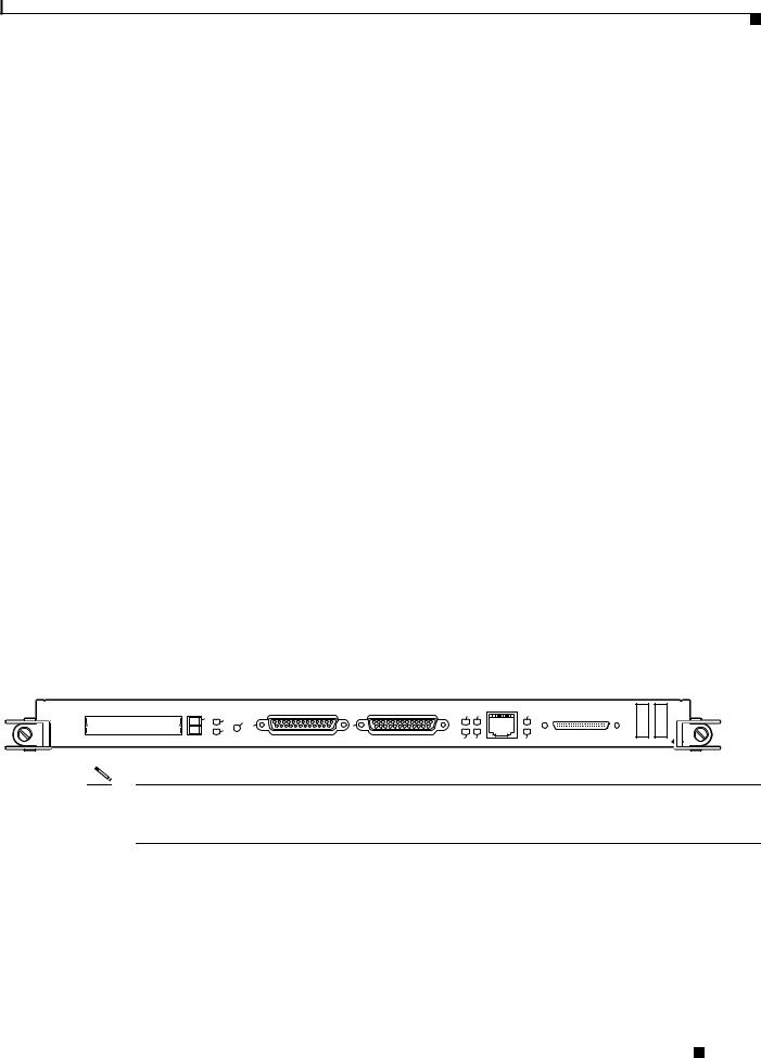
Information about the Gigabit Route Processor (GRP), its components, functions, and features, and its use as the system processor for Cisco 12000 Series Routers is presented in the following sections. Figure 1 shows the front view of the GRP.
Figure 1 Gigabit Route Processor (Front Panel, Horizontal Orientation)
EJECT |
-1 |
RESET |
|
|
COLL RX |
-45 |
SLOT |
|
|
RJ |
|||
|
-0 |
|
|
|
|
|
|
SLOT |
AUX |
CONSOLE |
LINK |
TX |
MII |
|
|
GIGABIT ROUTE PROCESSOR |
H10760 |
|
Note In order to maintain Class B EMI compliance, shielded cables must be used on the console and auxiliary ports of the GRP. An updated version of the GRP (Product Number GRP-B=, Rev. F0 and later) does not require shielded cables for Class B compliance.
GRP Functions
The primary functions of the GRP for Cisco 12000 Series Routers follow:
•Loading the Cisco IOS software on all the installed line cards at power up
•Providing a console (terminal) port for router configuration
Cisco IOS Software Requirements
|
78-4339-09 |
3 |
|
|
|

Product Overview
•Providing an auxiliary port for other external equipment (such as modems)
•Providing an IEEE 802.3, 10/100-megabits-per-second (Mbps) Ethernet port for Telnet functionality
•Running routing protocols
•Building and distributing routing tables to the line cards
•Providing general system maintenance functions
•Communicating with the line cards either through the switch fabric or through the maintenance bus (MBus)
The MBus connection allows the GRP to download a system bootstrap image, collect or load diagnostic information, and perform general, internal system maintenance operations. The switch fabric connection is the main data path for routing table distribution as well as for packets that are sent between line cards and the GRP.
GRP Components
The GRP contains the following components:
•RISC processor—IDT R5000 Reduced Instruction Set Computing (RISC) processor used for the CPU. The CPU runs at an external bus clock speed of 100 MHz and an internal clock speed of 200 MHz.
•DRAM—Up to 512 megabytes (MB) of parity-protected, extended data output (EDO) dynamic random-access memory (DRAM) on two 60-nanosecond (ns), dual in-line memory modules (DIMMs). 128 MB of DRAM is the minimum shipping configuration for the GRP.
Note GRP route memory configurations of 512 MB are only compatible with Product Number GRP-B=. In addition, Cisco IOS Release 12.0(19)S or 12.0(19)ST or later and ROMMON Release 11.2 (181) or later are also required.
•SRAM—512 kilobytes (KB) of static random-access memory (SRAM) for secondary CPU cache memory functions. (SRAM is not user configurable or field upgradeable.)
•NVRAM—512 KB of nonvolatile RAM (NVRAM). (NVRAM is not user configurable or field upgradeable.)
•Memory—Most of the additional memory components used by the system, including onboard Flash memory and up to two Personal Computer Memory Card International Association (PCMCIA)-based Flash memory cards and advanced technology attachment (ATA) Flash disks.
•Sensors—Air-temperature sensors for environmental monitoring.
Cisco IOS Software
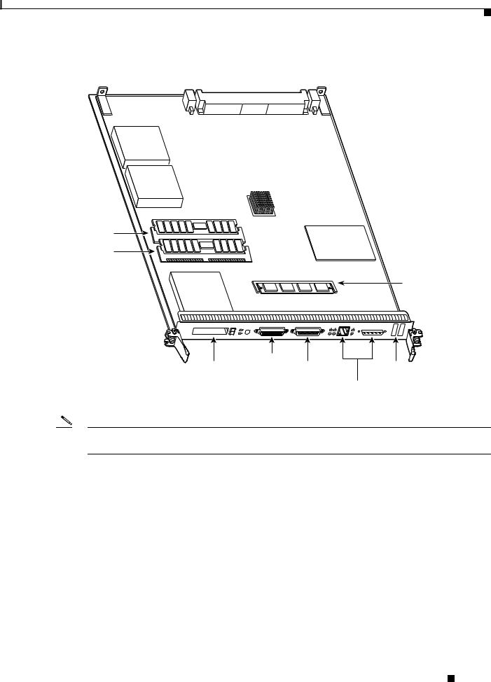
The Cisco IOS software images that run the Cisco 12000 Series Router system reside in Flash memory, which is located on the GRP in the form of a single in-line memory module (SIMM), and on up to two Flash cards (called Flash memory cards or Flash disks), which insert into the two slots (slot 0 and slot 1) on the front of the GRP. (See Figure 2.)
Note
GRP Components
4 |
78-4339-09 |
|
|
Product Overview
Figure 2 GRP (Horizontal Orientation)
Backplane connector
Bank 2 |
U42 |
DRAM DIMMs |
U39 |
Bank 1 |
U17 |
Flash |
|
SIMM |
||
|
CT |
-1 |
JE |
T |
E |
SLO |
|
T-0 |
|
SLO |
RESET AUX
|
LL |
RX |
-45 |
|
CO |
RJ |
|
K |
TX |
|
MII |
LIN |
|
|
|
GIGABIT ROUTE PROCESSOR 
H10547
|
Auxiliary port |
|
PCMCIA slots |
Console port |
Alphanumeric |
slot 0: bottom |
|
LED displays |
slot 1: top |
|
Ethernet |
|
|
interface |
|
|
(RJ-45 or MII) |
Note The onboard Flash memory (called bootflash) contains the Cisco IOS software boot image, and a Flash memory card or Flash disk contains the Cisco IOS software image.
Storing the Cisco IOS images in Flash memory enables you to download and boot from upgraded Cisco IOS software images remotely or from software images that reside in GRP Flash memory.
The Cisco 12000 Series Router system supports downloadable system software for most
Cisco IOS software upgrades, which enables you to remotely download, store, and boot from a new Cisco IOS software image. The Cisco IOS software runs from within GRP DRAM.
For specific Cisco IOS software requirements for the GRP, see the “Cisco IOS Software Requirements” section on page 3.
Cisco IOS Software
|
78-4339-09 |
5 |
|
|
|

Product Overview
Memory Components
Figure 2 shows the locations of the various types of memory used on the GRP. GRP memory component types are presented in the following sections:
•DRAM
•SRAM
•NVRAM
•Flash Memory
Their functions are presented in Table 1.
Table 1 |
GRP Memory Components |
|
|
|||
|
|
|
|
|
|
|
Type |
|
Size |
|
Quantity |
Description |
Location |
|
|
|
|
|
|
|
DRAM |
|
641 to 512 MB2 |
1 or 2 |
64-, 128-, or 256-MB DIMMs (based on the required DRAM |
U39 (bank 1) |
|
|
|
|
|
|
configuration) for main Cisco IOS software functions (default |
U42 (bank 2) |
|
|
|
|
|
configuration is 128 MB3) |
|
SRAM4 |
|
512 |
KB (fixed) |
— |
SRAM for secondary CPU cache memory functions |
— |
NVRAM5 |
|
512 |
KB (fixed) |
1 |
NVRAM for system configuration files |
— |
Flash memory |
8 MB SIMM6 |
1 |
Contains Cisco IOS software images, system configuration |
U17 |
||
|
|
|
|
|
files, and other user-defined files on the GRP |
|
|
|
|
|
|
|
|
— |
|
Flash memory7 |
1 to 2 |
Contains Cisco IOS software images, system configuration |
Flash disk |
|
|
|
|
|
|
files, and other user-defined files on up to two Flash memory |
slot 0 and |
|
|
|
|
|
cards or Flash disks8 |
slot 1 |
Flash boot |
|
512 |
KB |
1 |
Flash EPROM for the ROM monitor program boot image |
— |
ROM |
|
|
|
|
|
|
|
|
|
|
|
|
|
1.64 MB of DRAM serves as a replacement for any DRAM DIMM slot on a minimum configuration of 128 MB (both slots populated) for the GRP.
2.GRP route memory configurations of 512 MB are only compatible with Product Number GRP-B=. Cisco IOS Release 12.0(19)S or 12.0(19)ST or later and ROMMON Release 11.2 (181) or later are also required.
3.Default DRAM configuration is 128 MB. Bank 1 (U39) must be populated first. You can use one or both banks to configure DRAM up to 512 MB.
4.SRAM is not user configurable or field upgradeable.
5.NVRAM is not user configurable or field upgradeable.
6.SIMM socket is wired for Cisco’s own design and does not accept industry-standard 80-pin Flash SIMMs.
7.Cisco IOS Release 12.0(17)S or 12.0(17)ST or later is required, along with the corresponding boot images, for the GRP to function with a Flash disk.
8.Linear Flash memory cards and ATA Flash disks can be used in either (or both) Flash card slot(s).
DRAM
DRAM stores routing tables, protocols, and network accounting applications, and runs the Cisco IOS software. The standard (default) GRP configuration is 128 MB of extended data output (EDO) DRAM, with up to 512 MB available through DIMM upgrades.
Note GRP route memory configurations of 512 MB are only compatible with Product Number GRP-B=. In addition, Cisco IOS Release 12.0(19)S or 12.0(19)ST or later and ROMMON Release 11.2 (181) or later are also required.
Memory Components
6 |
78-4339-09 |
|
|

Product Overview
Caution To prevent memory problems, DRAM DIMMs must be +3.3VDC, 60-nanosecond (ns) EDO devices. Do not attempt to install other devices in the DIMM sockets. Cisco recommends that you use Cisco-approved memory options. (See Table 14 on page 49.)
The following DRAM upgrade kits for the GRP and line cards are listed by product number:
•64-MB DRAM upgrade kit (one 64-MB DIMM)—MEM-GRP/LC-64=
•128-MB DRAM upgrade kit (one 128-MB DIMM)—MEM-GRP/LC-128=
•256-MB DRAM upgrade kit (two 128-MB DIMMs)—MEM-GRP/LC-256=
The following DRAM upgrade kits for Product Number GRP-B= are available (listed by product number):
•256-MB DRAM upgrade kit (one 256-MB DIMM)—MEM-GRP-256=
•512-MB DRAM upgrade kit (two 256-MB DIMMs)—MEM-GRP-512-UPG=
These kits are available only for Product Number GRP-B=. They are not compatible with any other Cisco product. See Table 14 for all requirements related to the 512-MB memory upgrade.
Note MEM-GRP/LC-64= can be used to replace bank 1 or bank 2 in the 128-MB default configuration on the GRP line card. Cisco does not recommend using a 64-MB configuration on this card.
SRAM
SRAM provides secondary CPU cache memory. The standard GRP configuration is 512 KB. Its principal function is to act as a staging area for routing table updates information to and from the line cards. SRAM is not user configurable or field upgradeable.
NVRAM
System configuration files, software configuration register settings, and environmental monitoring logs are contained in the 512-KB NVRAM, which is backed up with built-in lithium batteries that retain the contents for a minimum of 5 years. NVRAM is not user configurable or field-upgradeable.
Flash Memory
Both the onboard and Flash card-based Flash memory allow you to remotely load and store multiple Cisco IOS software and microcode images. You can download a new image over the network or from a local server and then add the new image to Flash memory or replace the existing files. You can then boot the routers either manually or automatically from any of the stored images.
Flash memory also functions as a Trivial File Transfer Protocol (TFTP) server to allow other servers to boot remotely from stored images or to copy them into their own Flash memory. The onboard Flash memory (called bootflash) contains the Cisco IOS software boot image, and the Flash memory card or Flash disk contains the Cisco IOS software image.
Memory Components
|
78-4339-09 |
7 |
|
|
|

Product Overview
System Status LEDs
The two types of system status LEDs used on the GRP.
•Status LEDs
•Display LEDs
Status LEDs
The GRP has the following eight status LEDs:
•2 PCMCIA activity LEDs (one LED per PCMCIA slot)—Each LED goes on when its PCMCIA slot is accessed. The LEDs receive power from the switched slot voltage.
•4 RJ-45 Ethernet port LEDs—These LEDs are used in conjunction with the RJ-45 Ethernet connector. When the MII Ethernet port is in use, the LEDs are disabled. The LEDs indicate link activity (LINK), collision detection (COLL), data transmission (TX), and data reception (RX).
•2 RJ-45 or MII Ethernet port selection LEDs—These two LEDs, when on, identify which of the two Ethernet connections you selected. When the RJ-45 port is selected, its LED is on, and the MII LED is off. When the MII port is selected, its LED is on, and the RJ-45 LED is off.
Display LEDs
The alphanumeric display LEDs are organized as two rows of four characters each. The display content is controlled by the MBus software of the GRP. Both rows of the display are powered by the MBus module.
These alphanumeric display LEDs provide system status messages that are displayed during the boot process and after the boot process is completed.
During the boot process, the display LEDs are controlled directly by the MBus. After the boot process, they are controlled by the Cisco IOS software (via the MBus), and display messages designated by the Cisco IOS software.
The LED displays indicate the following:
•Status of the GRP
•System error messages
•User-defined status/error messages
Soft Reset Switch
A soft reset switch provides a reset to the R5000 software on the GRP. You access the soft reset switch through a small opening in the GRP faceplate. To depress the switch, insert a pape rclip or a similar object into the opening.
Caution To prevent system problems or loss of data, use the soft reset switch only on the advice of Cisco service personnel.
System Status LEDs
8 |
78-4339-09 |
|
|

Product Overview
Flash Card Slots
The GRP includes two Flash card slots. Either slot can support an ATA Flash disk or a linear Flash memory card.
Note The GRP only supports +5VDC Flash card devices. It does not support +3.3VDC Flash card devices.
All combinations of different Flash card devices are supported by the GRP. You can use ATA Flash disks, linear Flash memory cards, or a combination of the two. Each slot has an ejector button for ejecting a card from the slot.
Note Linear Flash memory cards may not have the capacity to meet the requirements of your configuration. However, they can be used for emergency file recovery applications.
Asynchronous Serial Ports
Two asynchronous serial ports on the GRP, the console and auxiliary ports, allow you to connect external serial devices to monitor and manage the system. The console port is an Electronic Industries Association/Telecommunications Industry Association (EIA/TIA)-232 receptacle (female) that provides a data circuit-terminating equipment (DCE) interface for connecting a console terminal.
Note EIA/TIA-232 was formerly RS-232.
The auxiliary port is an EIA/TIA-232 plug (male) that provides a data terminal equipment (DTE) interface; the auxiliary port supports flow control and is often used to connect a modem, a channel service unit (CSU), or other optional equipment for Telnet management.
Ethernet Port
The GRP has one Ethernet port available, using one of the following connection types:
•RJ-45 receptacle—8-pin RJ-45 receptacle for either IEEE 802.3 10BASE-T (10 Mbps) or IEEE 802.3u 100BASE-TX (100 Mbps) connections.
•MII receptacle—40-pin media independent interface (MII) receptacle that provides additional flexibility in Ethernet connections. The pinout of this standard 40-pin receptacle is defined by the IEEE 802.3u standard.
Note The RJ-45 and MII receptacles on the GRP represent two physical connection options for one Ethernet interface; therefore, you can use either the RJ-45 connection or the MII connection, but not both simultaneously.
The transmission speed of the Ethernet port is auto-sensing and is determined by the network to which the Ethernet interface is connected; it is not user configurable. At the auto-sensed data transmission rate of 100 Mbps, the Ethernet port provides maximum usable bandwidth that is less than 100 Mbps; a maximum usable bandwidth of approximately 20 Mbps can be expected if you use either the MII or RJ-45 connection.
Flash Card Slots
|
78-4339-09 |
9 |
|
|
|

Preparing for Installation
Preparing for Installation
Installation preparation is presented in the following sections:
•Safety Guidelines
•Translated Safety Warnings and Agency Approvals
•Electromagnetic Compatibility Regulatory Statements
•Preventing Electrostatic Discharge
•Working with Electrical Equipment
•Required Tools and Parts
Safety Guidelines
Before you perform any procedure in this publication, review the safety guidelines in this section to avoid injuring yourself or damaging the equipment.
The following guidelines are for your safety and to protect the equipment. The guidelines do not include all hazards. Be alert.
Note Review the safety warnings listed in the Regulatory Compliance and Safety Information for Cisco 12000 Series Internet Routers publication (Document Number 78-4347-xx) for your router before installing, configuring, or maintaining the GRP.
•Keep the work area clear and dust free during and after installation. Do not allow dirt or debris to enter into any components.
•Do not wear loose clothing, jewelry, or other items that could get caught in the router while working with the GRP.
•The GRP operates safely when it is used in accordance with its specifications and product usage instructions.
•Review all safety and ESD-prevention guidelines to help you to avoid injury or damage to the equipment.
•Ensure that your equipment configuration meets the minimum requirements for the upgrade or replacement you will perform and that you have all the parts and tools you need.
•If you plan to replace a GRP, back up your current configuration file to a remote server or to Flash memory before you remove the GRP. This prevents you from having to reenter all your current configuration information manually. To back up the file, copy your configuration file to a Flash disk or access a remote server.
Translated Safety Warnings and Agency Approvals
The complete list of safety warnings and agency approvals for the PRP is available in the Regulatory Compliance and Safety Information for Cisco 12000 Series Internet Routers publication (Document Number 78-4347-xx).
Preparing for Installation
10 |
78-4339-09 |
|
|
Preparing for Installation
Electromagnetic Compatibility Regulatory Statements
FCC Class A Compliance
This equipment has been tested and found to comply with the limits for a Class A digital device, pursuant to part 15 of the FCC rules. These limits are designed to provide reasonable protection against harmful interference when the equipment is operated in a commercial environment. This equipment generates, uses, and can radiate radio-frequency energy and, if not installed and used in accordance with the instruction manual, may cause harmful interference to radio communications. Operation of this equipment in a residential area is likely to cause harmful interference, in which case users will be required to correct the interference at their own expense.
Modifying the equipment without Cisco’s authorization may result in the equipment no longer complying with FCC requirements for Class A digital devices. In that event, your right to use the equipment may be limited by FCC regulation and you may be required to correct any interference to radio or television communication at your own expense.
You can determine whether your equipment is causing interference by turning it off. If the interference stops, it was probably caused by the Cisco equipment or one of its peripheral devices. If the equipment causes interference to radio or television reception, try to correct the interference by using one or more of the following measures:
•Turn the television or radio antenna until the interference stops.
•Move the equipment to one side or the other of the television or radio.
•Move the equipment farther away from the television or radio.
•Plug the equipment into an outlet that is on a different circuit from the television or radio. (That is, make certain the equipment and the television or radio are on circuits controlled by different circuit breakers or fuses.)
CISPR 22
This apparatus complies with EN55022 Class B radiated and conducted emissions requirements.
Canada
English Statement of Compliance
This class A digital apparatus complies with Canadian ICES-003.
French Statement of Compliance
Cet appareil numérique de la classe A est conforme à la norme NMB-003 du Canada.
Europe (EU)
This apparatus complies with EN55022 Class A and EN55024 standards when used as ITE/TTE equipment, and EN 300 386-2 (EN55022 class B with shielded CAT5 Ethernet cable, non-central office equipment) for Telecommunications Network Equipment (TNE).
Electromagnetic Compatibility Regulatory Statements
|
78-4339-09 |
11 |
|
|
|

Preparing for Installation
Class A Notice for Hungary
Warning This equipment is a class A product and should be used and installed properly according to the Hungarian EMC Class A requirements (MSZEN55022). Class A equipment is designed for typical commercial establishments for which special conditions of installation and protection distance are used.
Class A Notice for Taiwan and Other Traditional Chinese Markets
Warning This is a Class A Information Product, when used in residential environment, it may cause radio frequency interference, under such circumstances, the user may be requested to take appropriate countermeasures. Statement 257
VCCI Class A Notice for Japan
Warning This is a Class A product based on the standard of the Voluntary Control Council for Interference by Information Technology Equipment (VCCI). If this equipment is used in a domestic environment, radio disturbance may arise. When such trouble occurs, the user may be required to take corrective actions. Statement 191
Electromagnetic Compatibility Regulatory Statements
12 |
78-4339-09 |
|
|

Preparing for Installation
Class A Notice for Korea
Warning This is a Class A Device and is registered for EMC requirements for industrial use. The seller or buyer should be aware of this. If this type was sold or purchased by mistake, it should be replaced with a residential-use type. Statement 294
Preventing Electrostatic Discharge
Electrostatic discharge (ESD) damage, which can occur when electronic cards or components are improperly handled, results in complete or intermittent failures. Electromagnetic interference (EMI) shielding is an integral component of the GRP. Cisco recommends using a ESD-preventive strap whenever you are handling a router or one of its components.
Following are guidelines for preventing ESD damage:
•Always use an ESD-preventive wrist or ankle strap and ensure that it makes good skin contact. Connect the equipment end of the connection cord to an ESD connection socket on the router or to bare metal on the router chassis.
•Handle the GRP by the card carrier and by the left-side spring-loaded screw (horizontal view). Avoid touching board components or connector pins.
•Place a removed GRP board-side-up on an antistatic surface or in a static shielding bag. If you plan to return the component to the factory, immediately place it in a static shielding bag.
•Avoid contact between the GRP and clothing or jewelry. The wrist strap protects the board only from ESD voltages on the body; ESD voltages on clothing or jewelry can still cause damage.
Working with Electrical Equipment
Follow these basic guidelines when working with any electrical equipment:
•Before beginning any procedure requiring access to the chassis interior, locate the emergency power-off switch for the room in which you are working.
•Disconnect all power and external cables before moving a chassis.
•Do not work alone when potentially hazardous conditions exist; never assume that power has been disconnected from a circuit; always check.
•Do not perform any action that creates a potential hazard to people or makes the equipment unsafe.
•Carefully examine your work area for possible hazards such as moist floors, ungrounded power extension cables, and missing safety grounds.
Preventing Electrostatic Discharge
|
78-4339-09 |
13 |
|
|
|

Replacing a GRP
Required Tools and Parts
You need the following tools and parts to remove and replace a GRP. If you need additional equipment, contact a Cisco customer service representative for ordering information.
•3/16-inch flat-blade screwdriver for the captive installation screws that secure the GRP in its slot.
•ESD-prevention equipment or the disposable ESD-preventive wrist strap included with all spares and upgrade kits.
•Antistatic mat, foam pad, or bag for the removed GRP. Place the removed GRP into an antistatic bag if you plan to return it to the factory, or on an antistatic mat or foam if you are replacing components and will reinstall the GRP.
Replacing a GRP
The following sections describe the procedures for replacing a GRP in your system.
Before beginning the procedures, verify that your system meets the minimum requirements as described in the “Preparing for Installation” section on page 10.
When your system meets minimum requirements, proceed to the “Removing a GRP” section on page 14 for instructions on removing the GRP, and then to the “Installing a GRP” section on page 17 for reinstallation instructions.
Caution We recommend that you do not remove a GRP while the system is operating. Removing the installed GRP from a system while the system is operating will cause the system to stop forwarding packets and might cause the system to cease network operation.
Removing a GRP
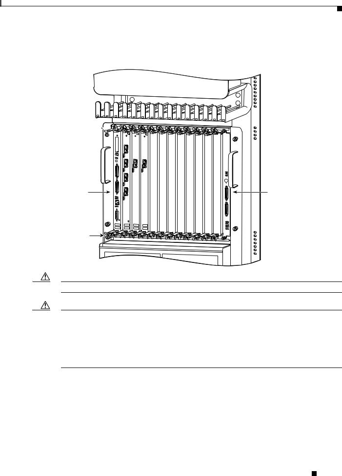
When you remove a GRP from a slot, be sure to use the ejector levers, which help to ensure that the GRP is fully dislodged from the backplane connector. (See Figure 3.)
Required Tools and Parts
14 |
78-4339-09 |
|
|
Replacing a GRP
Figure 3 GRP Ejector Levers, Captive Installation Screws, and Upper Card Cage Slots (Cisco 12012 Shown)
Ejector 


 lever and
 captive
screw
|
|
EJECT |
|
SLO |
|
|
|
T-0SLOT-1 |
|
AUX |
RESET |
|
CO |
|
|
NSO |
|
|
LE |
|
Upper |
|
|
card cage |
LINK |
RX |
|
TX |
COLL |
slot 0 |
MII |
|
|
|
RJ |
|
|
-45 |
|
PROCESSOR ROUTE GIGABIT |
|
Ejector |
lever and |
captive |
screw |
0
ACTIVE
CARRIERRX PKT
1
ACTIVE
CARRIERRX PKT
2
ACTIVE
CARRIERRX PKT
3
ACTIVE
CARRIERRX PKT
POS-3/STM-OC Q
0 |
0 |
ACTIVE |
ACTIVE |
CARRIER |
CARRIERRX |
RX |
|
CELL |
CELL |
ATM 4-12/STM-OC |
POS 4-12/STM-OC |
CRITICAL |
|
|
MAJOR |
|
|
MINOR |
|
|
|
ACO/LT |
|
|
|
1 ALARM |
|
|
2 ALARM |
ENABLEDFAIL |
|
|
|
0 |
|
|
1 |
CSC |
|
0 |
|
|
1 |
|
ALARM |
2 |
SFC |
|
|
|
Alarm card slot
H10761
Caution A GRP that is only partially removed from the backplane can halt the system.
Caution Before you replace the GRP, back up the running configuration to a Trivial File Transfer Protocol (TFTP) file server or an installed Flash memory card or Flash disk so that you can retrieve it later. If the configuration is not saved, the entire configuration will be lost inside the NVRAM on the removed GRP, and you will have to reenter the entire configuration manually. For instructions on how to save the configuration file, see the “Copying Files to Flash Memory” section on page 41. This procedure is not necessary if you are temporarily removing a GRP; lithium batteries will retain the configuration in memory until you replace the GRP in the system.
Figure 4 shows the ejector levers.
Removing a GRP
|
78-4339-09 |
15 |
|
|
|
Replacing a GRP
Figure 4 Ejector Levers and Captive Installation Screw (Cisco 12012 shown)
a Loosen captive screws
b Pivot ejector levers away from card to unseat card
GRP
cGrasp card carrier to slide card out of slot
|
|
|
0 |
|
|
|
|
|
|
|
E |
ACTIVE |
|
|
|
|
|
|
|
JECT |
CARRIERRX |
|
|
|
|
|
|
|
|
PKT |
|
|
|
|
|
|
SLOT-0SLOT-1 |
|
|
|
|
|
|
|
|
AUX |
RESET |
1 |
0 |
0 |
|
|
|
|
|
|
ACTIVE |
TIVE |
AC |
|
|
|
|
|
|
|
AC |
CRITIC |
|
|
|
|
|
|
CARRIERRX |
CAR |
CATIVE |
|
|
|
|
|
|
RXRIER |
RXRRI |
M AL |
|
||
|
|
|
PKT |
CEL |
CEER |
MAJOR |
|
|
|
|
|
|
L |
LL |
|
||
|
|
|
|
|
|
INOR |
|
|
|
CON |
|
2 |
|
|
|
|
|
|
SOLE |
|
|
|
|
|
|
|
|
EJ |
|
|
|
|
|
|
|
|
ECT |
|
ACTIVE |
|
|
|
ACO/LT |
|
OT-0OT-1 |
|
|
|
|
|
|||
SL |
SL |
|
CARRIERRX |
|
|
|
|
|
A |
RES |
|
PKT |
|
|
|
|
|
UX |
ET |
|
|
|
|
|
|
|
|
|
|
3 |
|
|
|
|
1ALARM |
|
LINK |
OLL |
ACTIVE |
|
|
|
|
|
|
TX |
|
|
|
|
|
||
|
|
C |
|
|
|
|
|
|
|
|
RX |
CARRIERRX |
|
|
|
|
|
C |
|
|
PKT |
|
|
|
|
|
ONS |
|
|
|
|
|
|
|
|
OLE |
|
|
|
|
|
|
|
|
|
MII |
|
|
|
|
|
|
|
|
|
R |
|
|
|
|
|
|
|
|
J-45 |
|
|
|
|
|
2 ALARM |
|
|
|
|
|
|
|
|
|
|
GIGABIT |
|
3/STM-OCQ |
12/STM-OC |
12/STM-OC |
|
|
|
|
ROUTE |
|
EN |
0 |
|
|||
LINK |
|
|
|
|
|
ABLEDFAIL |
|
|
|
C |
|
|
|
|
|
0 |
|
TX |
OLL |
|
|
|
|
|
1 |
CSC |
|
RX |
|
|
|
|
|
||
|
|
|
|
|
|
|
1 |
|
|
|
|
|
|
|
ALARM |
2 |
SFC |
M |
J-45 |
|
|
|
|
|
|
|
II |
R |
|
|
|
|
|
|
|
PROCESSOR ROUTE GIGABIT |
|
|
|
|
|
|
|
H10704 |
To remove a GRP, follow these steps:
Step 1 Turn off system power.
Step 2 If you are replacing the GRP in a system with one GRP, copy the currently running configuration file to a TFTP server or Flash memory so that you can retrieve it later. (See the “Copying Files to Flash Memory” section on page 41.)
Step 3 Attach an ESD-preventitive wrist strap to yourself and to one of the two ESD connection sockets located on the front edges of the upper card cage (Cisco 12012, Cisco 12016, or Cisco 12416); to the ESD connection socket located on the lower left edge of the upper card cage (Cisco 12008); or to bare metal on the frame.
If you are replacing a GRP, disconnect any devices that are attached to the console or auxiliary ports. If you are removing a GRP for maintenance and will reinstall the same one, you can leave the devices attached, provided that doing so will not strain the cables.
Step 4 Using a 3/16-inch flat-blade screwdriver, loosen the two captive screws on the ends of the GRP. (See Figure 4a.)
Step 5 Place your thumbs on the ends of each of the ejector levers and simultaneously pull them both away from the GRP faceplate (in the direction shown in Figure 4b) to release the GRP from the upper card cage slot and to dislodge the GRP edge connector from the backplane.
Step 6 Grasp the GRP faceplate with one hand and pull the GRP straight out of the slot, keeping your other hand under the GRP to guide it. (See Figure 4.) Keep the GRP edge connector parallel to the backplane.
Caution Avoid touching the GRP printed circuit board, components, or any edge connector pins.
Removing a GRP
16 |
78-4339-09 |
|
|

Replacing a GRP
Step 7 Place the removed GRP on an antistatic mat or foam. If you plan to return the GRP to the factory, immediately place it in an antistatic bag to prevent ESD damage.
Installing a GRP
When you install a GRP, be sure to use the ejector levers, which help to ensure that the GRP is fully inserted in the backplane connector. (See Figure 3.) When you simultaneously push the ejector levers inward (toward the center of the GRP), the ejector levers push the GRP into the slot and ensure that the GRP backplane connector is fully seated in the backplane.
Caution A GRP that is only partially connected to the backplane can halt the system.
Use the following procedure to install a GRP:
Step 1 Use an ESD-preventive wrist or ankle strap and follow its instructions for use.
Step 2 Grasp the GRP faceplate with one hand and place your other hand under the carrier to support and guide it into an upper card cage slot. (See Figure 4.)
Caution Avoid touching the GRP printed circuit board, components, or any edge connector pins.
Step 3 Place the bus-connector edge of the GRP in the appropriate slot and align the notches along the edge of the carrier with the grooves at the top and bottom of the slot.
Step 4 While keeping the GRP edge connector parallel to the backplane, carefully slide the carrier into the slot until the GRP faceplate makes contact with the ejector levers, then stop.
Step 5 Using the thumb and forefinger of each hand to pinch each ejector lever, simultaneously push both ejectors toward the center of the GRP faceplate until they are perpendicular to the GRP faceplate. (See Figure 4a.)
Step 6 Using a 3/16-inch flat-blade screwdriver, tighten the captive screws on the ends of the GRP. The captive screws prevent the GRP from becoming partially dislodged from the backplane and ensure proper EMI shielding. (These captive screws must be tightened to meet EMI specifications.)
Step 7 If you disconnected the console terminal to remove the GRP, or if you are installing a new GRP, connect the console terminal to the console port. (See the “Connecting to the Console Port” section on page 18.)
Step 8 Ensure that the console terminal is turned on.
Step 9 Turn on system power.
Step 10 Attach the network end of your RJ-45 or MII cable to your transceiver, switch, hub, repeater, DTE, or other external equipment. Be sure to use the appropriate strain relief on cable connections.
Installing a GRP
|
78-4339-09 |
17 |
|
|
|
Loading...