


 Loading...
ADMINISTRATION
GUIDE
Cisco Small Business Pro
ESW 500 Series Switches

|
6bZg^XVh =ZVYfjVgiZgh |
6h^V EVX^[^X =ZVYfjVgiZgh |
:jgdeZ =ZVYfjVgiZgh |
|
8^hXd HnhiZbh! >cX# |
8^hXd HnhiZbh JH6 EiZ# AiY# |
8^hXd HnhiZbh >ciZgcVi^dcVa 7K |
|
|||
|
HVc ?dhZ! 86 |
H^c\VedgZ |
6bhiZgYVb! I]Z CZi]ZgaVcYh |
|
8^hXd ]Vh bdgZ i]Vc '%% d[[^XZh ldgaYl^YZ# 6YYgZhhZh! e]dcZ cjbWZgh! VcY [Vm cjbWZgh VgZ a^hiZY dc i]Z 8^hXd LZWh^iZ Vi lll#X^hXd#Xdb$\d$d[[^XZh#
 889:! 88:CI! 8^hXd :dh! 8^hXd Ajb^c! 8^hXd CZmjh! 8^hXd HiVY^jbK^h^dc! 8^hXd IZaZEgZhZcXZ! 8^hXd LZW:m! i]Z 8^hXd ad\d! 98:! VcY LZaXdbZ id i]Z =jbVc CZildg` VgZ igVYZbVg`h0 8]Vc\^c\ i]Z LVn LZ Ldg`!
 A^kZ! EaVn! VcY AZVgc VcY 8^hXd HidgZ VgZ hZgk^XZ bVg`h06bZg^VcY 6XVhXZhh=ZVYfjGZ\^higVg!iZgh6^gdcZi! 6hncXDH! 7g^c\^c\ i]Z BZZi^c\6h^V EVX^[^XId Ndj!=ZVYfjVgiZgh8ViVanhi! 8896! 889E! 88>:! 88>E! 88C6!:jgdeZ88CE! 88HE!=ZVYfjVgiZgh88KE! 8^hXd! i]Z 8^hXd 8Zgi^[^ZY
>ciZgcZildg` :meZgi ad\d! |
8^hXd HnhiZbh! >cX# |
8^hXd HnhiZbh JH6 EiZ# AiY# |
8^hXd HnhiZbh >ciZgcVi^dcVa 7K |
8^hXd >DH! 8^hXd EgZhh! 8^hXd HnhiZbh! 8^hXd HnhiZbh 8Ve^iVa! i]Z 8^hXd HnhiZbh ad\d! 8^hXd Jc^in! 8daaVWdgVi^dc L^i]dji A^b^iVi^dc! :i]Zg;Vhi! :i]ZgHl^iX]! :kZci 8ZciZg! ;Vhi HiZe! ;daadl BZ |
|||
|
HVc ?dhZ! 86 |
H^c\VedgZ |
6bhiZgYVb! I]Z CZi]ZgaVcYh |
7gdlh^c\! ;dgbH]VgZ! <^\V9g^kZ! =dbZA^c`! >ciZgcZi6bZg^XVhFjdi^Zci! >DH!=ZVYfjVgiZgh^E]dcZ! ^Fj^X` HijYn! >gdcEdgi! i]Z >gdcEdgi6h^Vad\d!EVX^[^XA^\]iHig=ZVb!YfjVgiZghA^c`hnh! BZY^VIdcZ! BZZi^c\EaVXZ! BZZi^c\EaVXZ:jgdeZ =ZVYfjVgiZgh8]^bZ HdjcY! B<M! CZildg`Zgh! CZildg`^c\ |
|||
|
8^hXd HnhiZbh! >cX# |
8^hXd HnhiZbh JH6 EiZ# AiY# |
8^hXd HnhiZbh >ciZgcVi^dcVa 7K |
6XVYZbn! CZildg` GZ\^higVg! E8Cdl! E>M! EdlZgEVcZah! Egd8dccZXi! HXg^eiH]VgZ! HZcYZg7VhZ! HB6GIcZi! HeZXigjb :meZgi! HiVX`L^hZ! I]Z ;VhiZhi LVn id >cXgZVhZ Ndjg >ciZgcZi Fjdi^Zci! IgVchEVi]! LZW:m! VcY i]Z LZW:m |
|||
|
HVc ?dhZ! 86 |
H^c\VedgZ |
6bhiZgYVb! I]Z CZi]ZgaVcYh |
ad\d VgZ gZ\^hiZgZY igVYZbVg`h d[ 8^hXd HnhiZbh! >cX# VcY$dg ^ih V[[^a^ViZh ^c i]Z Jc^iZY HiViZh VcY XZgiV^c di]Zg Xdjcig^Zh# |
|
||
8^hXd ]Vh bdgZ i]Vc '%% d[[^XZh ldgaYl^YZ# 6YYgZhhZh! e]dcZ cjbWZgh! VcY [Vm cjbWZgh VgZ a^hiZY dc i]Z 8^hXd LZWh^iZ Vi lll#X^hXd#Xdb$\d$d[[^XZh#
6aa di]Zg igVYZbVg`h bZci^dcZY ^c i]^h YdXjbZci dg lZWh^iZ VgZ i]Z egdeZgin d[ i]Z^g gZheZXi^kZ dlcZgh# I]Z jhZ d[ i]Z ldgY eVgicZg YdZh cdi ^bean V eVgicZgh]^e gZaVi^dch]^e WZilZZc 8^hXd VcY Vcn di]Zg XdbeVcn# %-%.G Xd ]889:!Vh bdgZ88:CI!i]Vc8^hXd'%%:dh!d[[^XZh8^hXd Ajb^c!ldgaYl^YZ#8^hXd CZmjh!6YYgZhhZh!8^hXd HiVY^jbK^h^dc!e]dcZ8^hXdcjbWZgh!IZaZEgZhZcXZ!VcY8^hXd[VmLZW:m!cjbWZghi]Z 8^hXdVgZad\d!a^hiZY98:! VcYdcLZaXdbZi]Z 8^hXdid i]Z =jbVcLZWh^iZCZildg`Vi VgZlll#X^hXd#XdbigVYZbVg`h0 8]Vc\^c\$\di]Z$d[[^XZh#LVn LZ Ldg`!
© 2009 Cisco Systems, Inc. All rights reserved. |
OL-19128-01 |

Contents
Chapter : Getting Started |
12 |
Introduction |
12 |
Typical Installation Methods |
13 |
Default Configuration settings on the ESW 500 Series Switches |
14 |
Physical Connectivity |
14 |
Connecting to the Switch |
17 |
Using the Default Static IP Address |
17 |
Using a Dynamic IP Address Allocated to the Switch By DHCP |
22 |
Using the Cisco Configuration Assistant (CCA) |
24 |
Navigating The Cisco Switch Configuration Utility |
29 |
Using the Management Buttons |
29 |
Performing Common Configuration Tasks |
30 |
Checking the Software Version |
30 |
Checking the System Information |
30 |
Viewing what Devices are Attached to the Switch |
31 |
Configuring the VLAN Settings for the Switch |
32 |
Configuring individual ports using Cisco Smartport Roles |
33 |
Smartport Roles |
34 |
Checking the Device Power Consumption |
38 |
Saving the Configuration |
40 |
Upgrading the Firmware on the Switch |
41 |
Resetting the Device |
46 |
Manual Reset |
47 |
Logging Off the Device |
47 |
Using The Switch Console Port |
48 |
Selecting Menu Options and Actions |
48 |
Chapter : Managing Device Information |
52 |
Understanding the Dashboards |
52 |
Ports |
59 |
Health and Monitoring |
59 |
Common Tasks |
60 |
ESW 500 Series Switches Administration Guide |
3 |

Contents
Help |
60 |
Defining System Information |
60 |
Viewing Device Health |
62 |
Resetting the Device |
64 |
Managing Cisco Discovery Protocol |
65 |
Defining the Bonjour Discovery Protocol |
68 |
TCAM Utilization |
70 |
Chapter : Managing Smart Ports |
72 |
Configuring Smart Ports for Desktops |
73 |
Configuring Smart Ports for IP Phones and Desktops |
77 |
Configuring Smart Ports for Access Points |
80 |
Configuring Smart Ports for Switches |
82 |
Configuring Smart Ports for Routers |
84 |
Configuring Smart ports for Guests |
87 |
Configuring Smart ports for Servers |
89 |
Configuring Smart ports for Printers |
91 |
Configuring Smart ports for VS Camera |
94 |
Configuring Smart Ports for Other |
96 |
Chapter : Configuring System Time |
99 |
Defining System Time |
99 |
Defining SNTP Settings |
103 |
Defining SNTP Authentication |
105 |
Chapter : Configuring Device Security |
108 |
Passwords Management |
108 |
Modifying the Local User Settings |
110 |
Defining Authentication |
111 |
Defining Profiles |
111 |
Modifying an Authentication Profile |
114 |
ESW 500 Series Switches Administration Guide |
4 |

Contents
Mapping Authentication Profiles |
115 |
Defining TACACS+ |
117 |
Modifying TACACS+ Settings |
120 |
Defining RADIUS |
122 |
Modifying RADIUS Server Settings |
126 |
Defining Access Methods |
127 |
Defining Access Profiles |
128 |
Defining Profile Rules |
131 |
Modifying Profile Rules |
135 |
Defining Traffic Control |
137 |
Defining Storm Control |
138 |
Modifying Storm Control |
140 |
Defining Port Security |
141 |
Modifying Port Security |
145 |
Defining 802.1x |
146 |
Defining 802.1X Properties |
147 |
Defining Port Authentication |
149 |
Modifying 8021X Security |
152 |
Defining Authentication |
155 |
Modifying Authentication Settings |
157 |
Authenticated Hosts |
158 |
Defining Access Control |
160 |
Defining MAC Based ACL |
160 |
Adding Rule to MAC Based ACL |
164 |
Modifying MAC Based ACL |
166 |
Defining IP Based ACL |
168 |
Modifying IP Based ACL |
174 |
Adding an IP Based Rule |
177 |
Defining ACL Binding |
179 |
Modifying ACL Binding |
180 |
Defining DoS Prevention |
181 |
DoS Global Settings |
181 |
ESW 500 Series Switches Administration Guide |
5 |

Contents
Defining Martian Addresses |
183 |
Defining DHCP Snooping |
185 |
Defining DHCP Snooping Properties |
186 |
Defining DHCP Snooping on VLANs |
188 |
Defining Trusted Interfaces |
189 |
Binding Addresses to the DHCP Snooping Database |
191 |
Query By |
192 |
Query Results |
193 |
Defining IP Source Guard |
195 |
Configuring IP Source Guard Properties |
195 |
Defining IP Source Guard Interface Settings |
197 |
Querying the IP Source Binding Database |
199 |
TCAM Resources |
200 |
Query By |
201 |
Query Results |
201 |
Defining Dynamic ARP Inspection |
202 |
Defining ARP Inspection Properties |
203 |
Defining ARP Inspection Trusted Interfaces |
205 |
Defining ARP Inspection List |
207 |
Static ARP Inspection Table |
208 |
Adding a Binding List entry |
209 |
Assigning ARP Inspection VLAN Settings |
210 |
Enabled VLAN Table |
211 |
Chapter : Configuring Ports |
213 |
Port Settings |
213 |
Modifying Port Settings |
215 |
Chapter : Configuring VLANs |
219 |
Defining VLAN Properties |
220 |
Modifying VLANs |
222 |
Defining VLAN Membership |
223 |
Modifying VLAN Membership |
224 |
ESW 500 Series Switches Administration Guide |
6 |

Contents
Assigning Ports to Multiple VLANs |
226 |
Defining Interface Settings |
229 |
Modifying VLAN Interface Settings |
230 |
Defining GVRP Settings |
232 |
Modifying GVRP Settings |
234 |
Defining Protocol Groups |
236 |
Modifying Protocol Groups |
237 |
Defining a Protocol Port |
238 |
Chapter : Configuring IP Information |
241 |
IP Addressing |
241 |
Defining DHCP Relay |
243 |
Defining DHCP Relay Interfaces |
245 |
Managing ARP |
247 |
ARP Table |
249 |
Modifying ARP Settings |
250 |
Domain Name System |
251 |
Defining DNS Servers |
251 |
Default Parameters |
252 |
DNS Server Details |
253 |
Mapping DNS Hosts |
253 |
Chapter : Defining Address Tables |
256 |
Defining Static Addresses |
256 |
Defining Dynamic Addresses |
259 |
Query By Section |
261 |
Chapter : Configuring Multicast Forwarding |
262 |
IGMP Snooping |
262 |
Modifying IGMP Snooping |
264 |
Defining Multicast Group |
266 |
ESW 500 Series Switches Administration Guide |
7 |

Contents
Modifying a Multicast Group |
268 |
Defining Multicast Forwarding |
269 |
Modifying Multicast Forwarding |
271 |
Defining Unregistered Multicast Settings |
272 |
Chapter : Configuring Spanning Tree |
275 |
Defining STP Properties |
275 |
Global Settings |
276 |
Defining Spanning Tree Interface Settings |
278 |
Modifying Interface Settings |
282 |
Defining Rapid Spanning Tree |
284 |
Modifying RTSP |
287 |
Defining Multiple Spanning Tree |
289 |
Defining MSTP Properties |
290 |
Defining MSTP Instance to VLAN |
291 |
Defining MSTP Instance Settings |
293 |
Defining MSTP Interface Settings |
294 |
Chapter : Configuring Quality of Service |
301 |
Managing QoS Statistics |
302 |
Policer Statistics |
302 |
Add Aggregated Policer Statistics |
304 |
Resetting Aggregate Policer Statistics Counters |
307 |
Queues Statistics |
307 |
Adding Queues Statistics |
309 |
Resetting Queue Statistics Counters |
309 |
Defining General Settings |
310 |
Defining CoS |
310 |
Modifying Interface Priorities |
312 |
Defining QoS Queue |
313 |
Mapping CoS to Queue |
316 |
Mapping DSCP to Queue |
318 |
ESW 500 Series Switches Administration Guide |
8 |

Contents
Configuring Bandwidth |
319 |
Modifying Bandwidth Settings |
320 |
Configuring VLAN Rate Limit |
322 |
Modifying the VLAN Rate Limit |
324 |
Defining Advanced QoS Mode |
324 |
Configuring DSCP Mapping |
325 |
Defining Class Mapping |
327 |
Defining Aggregate Policer |
329 |
Modifying QoS Aggregate Policer |
331 |
Configuring Policy Table |
332 |
Modifying the QoS Policy Profile |
335 |
Defining Policy Binding |
337 |
Modifying QoS Policy Binding Settings |
339 |
Defining QoS Basic Mode |
340 |
Rewriting DSCP Values |
341 |
Chapter : Configuring SNMP |
343 |
SNMP Versions |
343 |
SNMP v1 and v2 |
343 |
SNMP v3 |
343 |
Configuring SNMP Security |
344 |
Defining the SNMP Engine ID |
344 |
Defining SNMP Views |
346 |
Defining SNMP Users |
348 |
Modifying SNMP Users |
350 |
Define SNMP Groups |
351 |
Modifying SNMP Group Profile Settings |
354 |
Defining SNMP Communities |
355 |
Modifying SNMP Community Settings |
358 |
Defining Trap Management |
359 |
Defining Trap Settings |
359 |
Configuring Station Management |
361 |
ESW 500 Series Switches Administration Guide |
9 |

Contents
Modifying SNMP Notifications |
365 |
Defining SNMP Filter Settings |
367 |
Managing Cisco Discovery Protocol |
370 |
Chapter : Managing System Files |
373 |
Software Upgrade |
374 |
Save Configuration |
375 |
Copy Configuration |
377 |
Via TFTP |
378 |
Via HTTP |
379 |
Active Image |
379 |
DHCP Auto Configuration |
381 |
Chapter : Managing Power-over-Ethernet Devices |
382 |
Defining PoE Settings |
382 |
Chapter : Managing System Logs |
386 |
Enabling System Logs |
386 |
Viewing the Device Memory Logs |
388 |
Clearing Message Logs |
389 |
Viewing the System Flash Logs |
390 |
Clearing Flash Logs |
391 |
Remote Log Servers |
391 |
Modifying Syslog Server Settings |
394 |
Chapter : Viewing Statistics |
397 |
Viewing Ethernet Statistics |
397 |
Defining Interface Statistics |
397 |
Resetting Interface Statistics Counters |
399 |
Viewing Etherlike Statistics |
399 |
Resetting Etherlike Statistics Counters |
401 |
Viewing GVRP Statistics |
401 |
ESW 500 Series Switches Administration Guide |
10 |
Contents
Resetting GVRP Statistics Counters |
403 |
Viewing EAP Statistics |
403 |
Managing RMON Statistics |
405 |
Viewing RMON Statistics |
406 |
Resetting RMON Statistics Counters |
408 |
Configuring RMON History |
408 |
Defining RMON History Control |
408 |
Viewing the RMON History Table |
411 |
Defining RMON Events Control |
413 |
Modifying RMON Event Log Settings |
415 |
Viewing the RMON Events Logs |
416 |
Defining RMON Alarms |
417 |
Modifying RMON Alarm Settings |
421 |
Chapter : Aggregating Ports |
424 |
Defining EtherChannel Management |
425 |
Defining EtherChannel Settings |
427 |
Modifying EtherChannel Settings |
429 |
Configuring LACP |
431 |
Chapter : Managing Device Diagnostics |
434 |
Ethernet Port Testing |
434 |
Performing GBIC Uplink Testing |
437 |
Configure Span (Port Mirroring) |
438 |
Monitoring CPU Utilization |
440 |
ESW 500 Series Switches Administration Guide |
11 |

Getting Started
Introduction
Getting Started
Introduction
Thank you for choosing the Cisco Small Business Pro ESW 500 Series Switch. The ESW 500 series is a family of Ethernet switches that addresses network infrastructure and access needs of small business customers for voice, data, PCs, Servers, and video applications. They are simple to deploy and manage for use with IP phones, Access Points, IP cameras, and Network Attached Storage servers as well as most any Ethernet device. The ESW 500 series includes seven Fast Ethernet and GigE switches in both 24and 48-port configurations with PoE and non-PoE options. The ESW 500 series also includes two 8 port PoE switches in Fast Ethernet and GigE models. The switch models covered in this guide are:
ESW 500 Series Switch |
Port Configuration |
ESW 520-8P |
8 Port 10/100 PoE |
ESW 540-8P |
8 Port 10/100/1000 PoE |
ESW 520-24 |
24 Port 10/100 |
ESW 520-24P |
24 Port 10/100 PoE |
ESW 520-48 |
48 Port 10/100 |
ESW 520-48P |
48 Port 10/100 PoE |
ESW 540-24 |
24 Port 10/100/1000 |
ESW 540-24P |
24 Port 10/100/1000 PoE |
ESW-540-48 |
48 Port 10/100/1000 |
This section provides information about the different methods to connect to the switch, as well as some examples of a typical installation. It also provides an introduction to the user interface, and includes the following:
•Typical Installation Methods, page 13
•Connecting to the Switch, page 17
-Using the Default Static IP Address, page 17
-Using a Dynamic IP Address Allocated to the Switch By DHCP, page 22
-Using the Cisco Configuration Assistant (CCA), page 24
•Navigating The Cisco Switch Configuration Utility, page 29
ESW 500 Series Switches Administration Guide |
12 |
Getting Started
Typical Installation Methods
•
•
Performing Common Configuration Tasks, page 30
Using The Switch Console Port, page 48
Typical Installation Methods
The first step in any installation scenario is to connect to the switch and configure basic connectivity to ensure it communicates with the rest of the network.
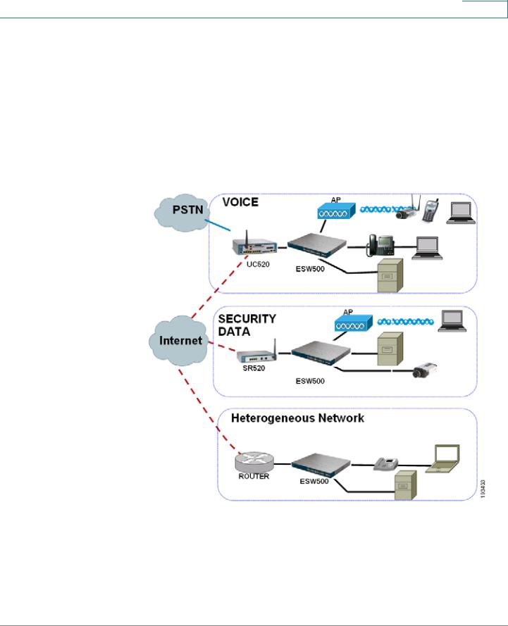
The following diagram illustrates three common installation scenarios:
In the first two scenarios, called VOICE and SECURITY DATA, you are adding an ESW 500 switch to a new or existing Cisco Smart Business Communications Systems (SBCS) network deployment. This deployment is either a VOICE network with UC520 being the anchor device or SECURITY / DATA network with the SR520 being the anchor device.
ESW 500 Series Switches Administration Guide |
13 |
Getting Started
Typical Installation Methods
In the third scenario, called Heterogeneous Network, you are adding an ESW 500 switch to a network which does not have any Cisco Small Business products.
Default Configuration settings on the ESW 500 Series
Switches
The ESW 500 series switches ship with a default configuration that enables simplified installation and plug and play when connected into a Cisco Small Business network such as SBCS. The default settings are as follows:
•
•
•
•
Management VLAN is VLAN 1
Management IP Address is obtained via DHCP by default. If the switch times out on a Dynamic Host Configuration Protocol (DHCP) response, it falls back to a static IP address 192.168.10.2 with subnet mask of 255.255.255.0.
Voice VLAN is VLAN 100
Cisco Discovery Protocol (CDP) is enabled on all ports
Physical Connectivity
Physical connections to the switch are described in the tables and graphics on the next two pages.
|
Uplink Ports |
|
|
ESW 500 Series Switch |
Copper |
SFP (mini-GBIC) |
Layer 2 Ethernet Ports |
ESW 520-8P |
GE1 |
GE1 |
1-8 |
ESW 540-8P |
GE1 |
GE1 |
1-8 |
ESW 520-24/24P |
GE1-GE4 |
GE3-GE4 |
1-24 |
ESW 520-48/48P |
GE1-GE2 |
GE3-GE4 |
1-48 |
ESW 540-24/24P |
11-12, 23-24 |
GE1-GE4 |
1-10, 13-22 |
ESW 540-48 |
23-24, 47-48 |
GE1-GE4 |
1-22, 25-46 |
NOTE On the 8 port devices, the Uplink and the GBIC ports can not be used at the same time.
ESW 500 Series Switches Administration Guide |
14 |

Getting Started
Typical Installation Methods
The ESW 540-24/24P and ESW 540-48 use shared ports. When connecting to uplink ports, the GE ports take precedence over the Copper ports. For example, on an ESW 540-24, if you plug a device into GE1, you cannot use port 11. The other port relationships are shown in the following table:
ESW 500 Series Switch |
GE Port |
Takes Precedence Over Copper Port |
ESW 540-24/24P |
GE1 |
11 |
ESW 540-24/24P |
GE2 |
23 |
ESW 540-24/24P |
GE3 |
12 |
ESW 540-24/24P |
GE4 |
24 |
ESW 540-48 |
GE1 |
23 |
ESW 540-48 |
GE2 |
47 |
ESW 540-48 |
GE3 |
24 |
ESW 540-48 |
GE4 |
48 |
Compare the following table with the four examples of switch front panels that are on the next page:
# |
Port |
Description |
|
|
|
1 |
Switch |
The switch is equipped with auto-sensing, Ethernet (802.3) network ports |
|
Ports |
which use RJ-45 connectors. The Ethernet ports support network |
|
|
speeds of 10 Mbps, 100 Mbps, or 1000 Mbps. They can operate in half |
|
|
and full-duplex modes. Auto-sensing technology enables each port to |
|
|
automatically detect the speed of the device connected to it, and adjust |
|
|
its speed and duplex accordingly. These ports are typically used for |
|
|
devices such as PCs, servers, IP phones and Access Points., and are |
|
|
highlighted RED in the examples. |
|
|
|
2 |
Uplink |
These ports are typically used for connecting to other switches, routers, |
|
Ports |
or network backbone devices, and are highlighted in YELLOW in the |
|
|
examples. The mini-GBIC ports are a type of uplink port. |
|
|
|
3 |
mini- |
The mini-GBIC (Gigabit Interface Converter) port is a connection point for |
|
GBIC |
a mini-GBIC expansion module, allowing the switch to be uplinked via |
|
Ports |
fiber to another switch. Each mini-GBIC port provides a link to a high- |
|
|
speed network segment or individual workstation at speeds of up to |
|
|
1000 Mbps. The mini-GBIC ports are highlighted in GREEN in the |
|
|
examples. |
|
|
|
ESW 500 Series Switches Administration Guide |
15 |

Getting Started
Typical Installation Methods
ESW-520-24/24P
ESW-520-48/48P
ESW-540-24/24P
ESW-540-48
ESW 500 Series Switches Administration Guide |
16 |
Getting Started
Connecting to the Switch
Connecting to the Switch
This section contains information for starting the Switch Configuration Utility to provision the switch features. There are four different options to connect to the switch, three of which launch the Switch Configuration Utility.They are:
•
•
•
Using the default static IP address of the switch
Using Cisco Configuration Assistant
Using a dynamic IP address allocated to the switch via DHCP (from DHCP server)
• Using the Console
The first three options to connect to the switch will open the ESW 500 Series Switch Configuration Utility, which is a web-based device manager used to provision the switch. The console option uses a terminal emulation program such as HyperTerminal (bundled with Windows) or Putty (freeware).
NOTE Using the Console does not launch the Switch Configuration Utility and is recommended for advanced users only. Using the Console is discussed at the end of this chapter.
Using the Default Static IP Address
To start configuring the switch, follow these steps:
STEP 1 Make sure that there are no devices connected to the switch, the switch is not connected to the network, and then power up the switch by connecting the power cord.
NOTE If the switch was previously connected to the network, it may have obtained an IP address from a DHCP server. To perform a static IP address installation, disconnect all devices and remove the switch from the network. Then perform a power cycle of the switch by unplugging the power cable, waiting 5 seconds, and plugging it back in.
STEP 2 Connect a PC to port 1 of the switch with an ethernet cable.
ESW 500 Series Switches Administration Guide |
17 |
Getting Started
Connecting to the Switch
STEP 3 If your PC is using a static IP address, make note of your current IP address settings, and record them for future use.
STEP 4 Place the PC on the same subnet of the switch by configuring the PC with the following parameters:
•Static IP address — 192.168.10.11
•Subnet mask — 255.255.255.0
•Default gateway — 192.168.10.2
NOTE Details on how to change the IP address on your PC are dependent upon the type of architecture and operating system installed. Use your PC’s local Help and Support functionality and search for “IP Addressing”.
STEP 5 Open a web browser. Cisco recommends Internet Explorer version 6 or higher, or Firefox version 3. Accept any requests to install Active-X plugin.
Enter http://192.168.10.2 in the address bar and press Enter. The Log In page opens:
ESW 500 Series Switches Administration Guide |
18 |
Getting Started
Connecting to the Switch
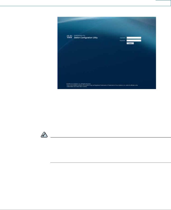
Log In page
STEP 6 Enter a user name and password. The default user name is cisco and the default password is cisco. Passwords are both case sensitive and alpha-numeric. Click Log In.
STEP 7 While the system is verifying the login attempt, the Log In Progress Indicator appears. The indicator dots rotate clockwise to indicate that the system is still working. If the login attempt is successful, the Change Username/Password Page opens.
NOTE After logging in using the default username and password you must change to a new username and password. Only after the change has been made, can you operate the device through the web browser. Every time you log in using cisco as the username and password, you will be redirected to the Change Username/Password Page.
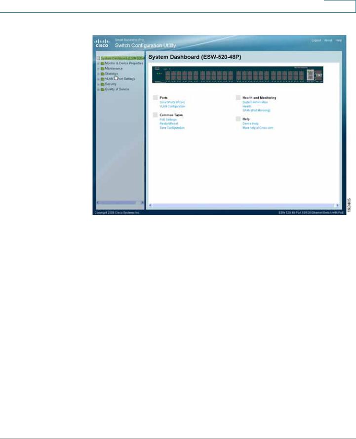
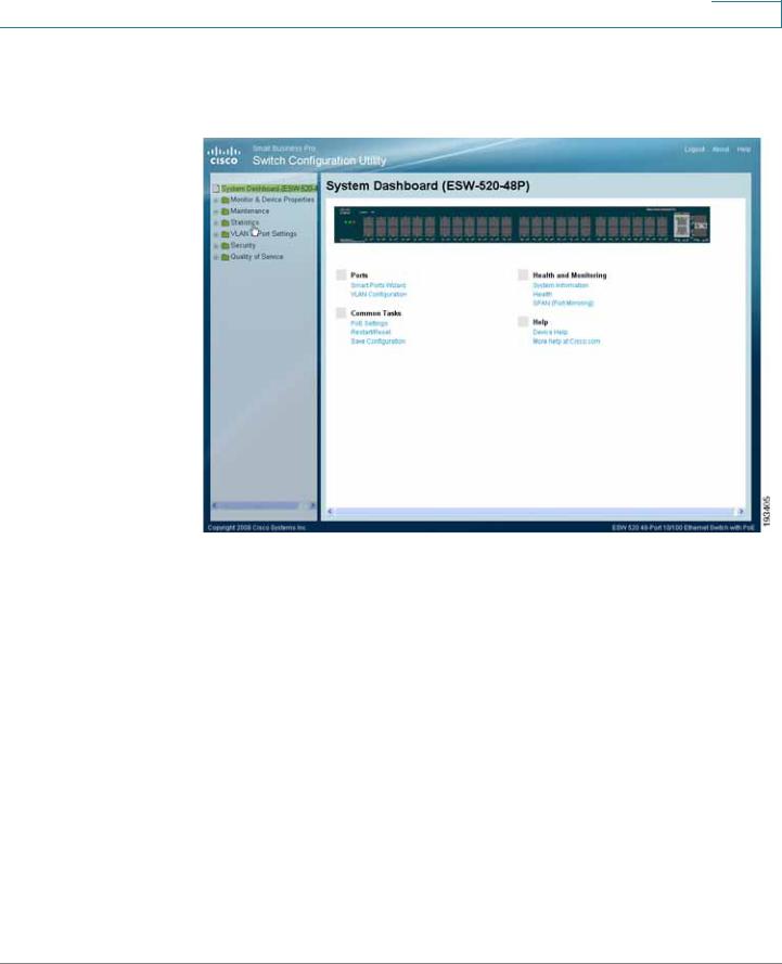
STEP 8 Click Apply. The Switch Configuration Utility - System Dashboard Page opens.
ESW 500 Series Switches Administration Guide |
19 |
Getting Started
Connecting to the Switch
Switch Configuration Utility - System Dashboard
STEP 9 Click Monitor & Device Properties > System Management > IP Addressing > IPv4 Interface.The IPv4 Interface page opens.
ESW 500 Series Switches Administration Guide |
20 |
Getting Started
Connecting to the Switch
IPv4 Interface Page
NOTE It is expected that the IP address to be assigned to the switch is known prior to installation, based on the network topology.
STEP 10 Select the Static IP address radio button and enter the IP Address, Network Mask and User Defined Default Gateway. These must match the IP addressing subnet in the network in which the ESW 500 switch will be deployed. Click Apply.
NOTE The PC loses the connection to the switch at this point.
STEP 11 Now that you have finished using the PC to connect to the switch and made the switch part of your network, you can reconfigure the PC to its original IP address configuration and physical configuration as part of your network.
STEP 12 You are now ready to proceed with additional switch configuration.
ESW 500 Series Switches Administration Guide |
21 |
Getting Started
Connecting to the Switch
NOTE If you will be using this PC for further switch configuration, it will need to be on the same subnet as the switch.
Using a Dynamic IP Address Allocated to the Switch By DHCP
If this method of obtaining an IP address is used, you will need to have access to a configuration device that would allow you to see what IP addresses the DHCP server allocates. Prior to choosing this method of installation, speak with your network administrator to ensure you will have the correct information available to you.
NOTE By default, the IP address of the device is assigned dynamically.
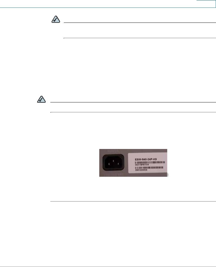
Log on to the DHCP server and check the IP address corresponding to the Media Access Control (MAC) address of the switch. On the 24 and 48 port models, the MAC address is on the back panel of the switch next to the power adapter. On the 8 port models, the MAC address is on the bottom of the device. The illustration below shows a MAC address of 00211BFE7218.
Once you have the correct IP address that has been assigned to the switch, you can begin configuring the switch.
STEP 1 Open a web browser. Cisco recommends Internet Explorer version 6 or higher, or Firefox version 3 or higher.
Enter the IP address that has been assigned to the switch in the address bar and press Enter. The Log In page opens:
ESW 500 Series Switches Administration Guide |
22 |

Getting Started
Connecting to the Switch
Log In page
STEP 2 Enter a user name and password. The default user name is cisco and the default password is cisco. Passwords are both case sensitive and alpha-numeric.
STEP 3 Click Log In. The Switch Configuration Utility - System Dashboard Page opens.
STEP 4 A window opens that prompts you to change your username and password from the default. Choose a new username and password, then click Apply.
ESW 500 Series Switches Administration Guide |
23 |

Getting Started
Connecting to the Switch
Switch Configuration Utility - System Dashboard
STEP 5 You are now ready to proceed with additional switch configuration.
Using the Cisco Configuration Assistant (CCA)
NOTE To perform an installation using CCA, you must have a PC with Windows Vista Ultimate or Windows XP, Service Pack 1 or later installed and CCA version 2.2 or higher installed.
The Cisco Configuration Assistant can be used to connect to and configure the switch when there is an existing or new Smart Business Communications System (SBCS) or with other Cisco Small Business Pro products such as the SA 500 Series Security Appliance or the AP 541 Access Point. The ESW 500 series switch obtains the management IP address via DHCP after it is connected to the network.
To begin installing the switch using CCA, perform the following steps:
ESW 500 Series Switches Administration Guide |
24 |
Getting Started
Connecting to the Switch
STEP 1 Power on the ESW 500 series switch.
STEP 2 Connect one of the designated uplink ports on the ESW 500 series switch to the expansion port on the UC520 or one of the switch ports on the SR520.
STEP 3 Connect the PC with CCA installed to any access switch port on the ESW 500 or alternately, the UC500 or Small Business Pro router.
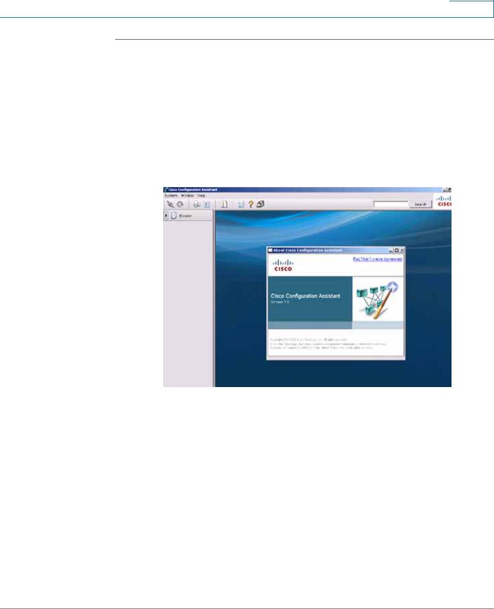
STEP 4 Launch CCA. To verify you have CCA version 2.2 or higher, click Help > About. The version page opens.
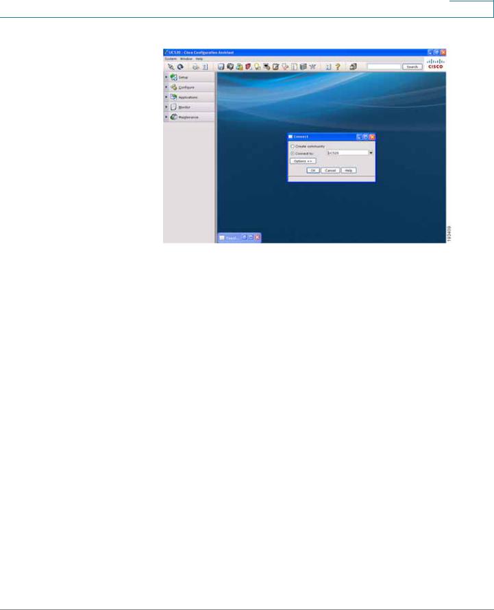
CCA Version page
STEP 5 Connect to an existing community, or create a new one. For more information on how to create a community, refer to the "How to create a CCA community" VOD at https://www.myciscocommunity.com/docs/DOC1423#UC500_System_Level_Features
ESW 500 Series Switches Administration Guide |
25 |
Getting Started
Connecting to the Switch
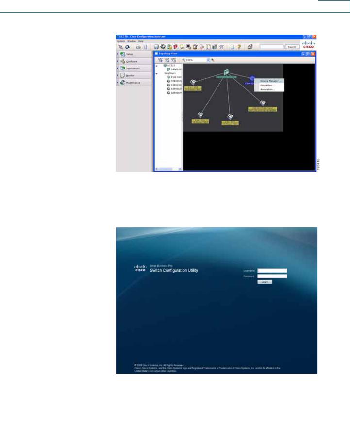
Connect page
STEP 6 Once you have connected to the community, the Topology View opens and displays the ESW 500 Series Switch. Right-click on the switch and it displays three options:
•
•
•
Device Manager
Properties
Annotation
You can now continue with configuring the switch by two different options; use CCA to do all of the configuration, or use the Device Manager to go to the switch Configuration Utility. Additional information is described in detail in the appropriate CCA user documentation. This procedure uses the Device Manager.
ESW 500 Series Switches Administration Guide |
26 |
Getting Started
Connecting to the Switch
CCA Topology View page
STEP 7 Click on Device Manager.
The Log In page will launch in a new browser window.
Log In page
STEP 8 Enter a user name and password. The default user name is cisco and the default password is cisco. Passwords are both case sensitive and alpha-numeric.
STEP 9 Click Log In. The Switch Configuration Utility - System Dashboard Page opens.
ESW 500 Series Switches Administration Guide |
27 |
Getting Started
Connecting to the Switch
STEP 10 A window opens that prompts you to change your username and password from the default. Choose a new username and password, then click Apply.
Switch Configuration Utility - System Dashboard
STEP 11 You are now ready to proceed with additional switch configuration.
ESW 500 Series Switches Administration Guide |
28 |
Getting Started
Navigating The Cisco Switch Configuration Utility
Navigating The Cisco Switch Configuration Utility
The Cisco Switch Configuration Utility is a web-based device manager that is used to provision the switch. You must have IP connectivity between the PC and the switch to configure the switch. The following section describes how to navigate within the interface.
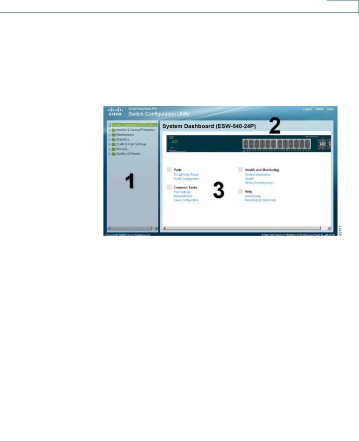
Switch Configuration Utility - System Dashboard Page
The following table lists the interface components with their corresponding numbers:
Component |
Description |
1 Navigation Pane |
The navigation pane provides easy navigation through the |
|
configurable device features.The main branches expand |
|
to provide the subfeatures. |
2 Device View |
The device view contains a graphical representation of |
|
the device faceplate, including the device status and port |
|
LEDs. Clicking on a port will open up the Edit Port Page. |
3 Getting Started |
The getting started links allow you to navigate through the |
Links |
different device features. |
Using the Management Buttons
Device Management buttons and icons provide an easy method of configuring device information.
ESW 500 Series Switches Administration Guide |
29 |
Getting Started
Performing Common Configuration Tasks
Performing Common Configuration Tasks
Once the Switch Configuration Utility has been launched and you have logged into the switch, these are some examples of the common configuration tasks you can perform. Use the menus in the left navigation panel to choose a specific area of configuration.
Checking the Software Version
To check the version of the software on the switch, click About at the top of the page.
Software Version Page
Checking the System Information
Click on Monitor & Device Properties > System Management > System
Information. The System Information page opens.
ESW 500 Series Switches Administration Guide |
30 |
Loading...