


 Loading...
Cisco Model DPC/EPC2325 DOCSIS
Residential Gateway with Wireless
Access Point User Guide
In This Document |
|
|
|
IMPORTANT SAFETY INSTRUCTIONS ............................................................... |
2 |
|
Introduction................................................................................................................. |
9 |
What's In the Carton?............................................................................................... |
11 |
|
|
Front Panel Description ........................................................................................... |
12 |
|
Back Panel Description ............................................................................................ |
13 |
Where Is the Best Location for My DOCSIS Residential Gateway? .................. |
14 |
|
How Do I Mount the Modem on a Wall? (Optional)........................................... |
15 |
|
What Are the System Requirements for Internet Service?.................................. |
18 |
|
How Do I Subscribe to High-Speed Internet Service?......................................... |
19 |
|
How Do I Connect My Devices to Use the Internet?........................................... |
20 |
|
How Do I Configure My DOCSIS Residential Gateway? ................................... |
22 |
|
How Do I Troubleshoot My Internet Service Installation?................................. |
96 |
|
|
Frequently Asked Questions................................................................................... |
97 |
|
Having Difficulty? .................................................................................................. |
104 |
Tips for Improved Performance ........................................................................... |
105 |
|
Front Panel LED Status Indicator Functions....................................................... |
106 |
|
|
For Information....................................................................................................... |
109 |
|
Notices...................................................................................................................... |
110 |
Third Party Software License Notices For Cisco Model DPC/EPC2325 |
|
|
|
DOCSIS Residential Gateway with Wireless Access......................................... |
111 |
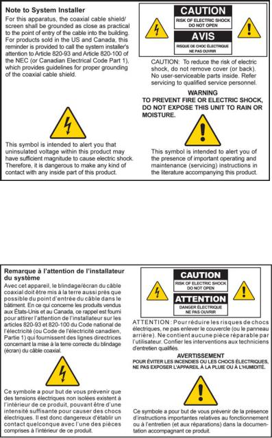
IMPORTANT SAFETY INSTRUCTIONS
IMPORTANT SAFETY INSTRUCTIONS
Notice to Installers
The servicing instructions in this notice are for use by qualified service personnel only. To reduce the risk of electric shock, do not perform any servicing other than that contained in the operating instructions, unless you are qualified to do so.
Notice à l’attention des installateurs de réseaux câblés
Les instructions relatives aux interventions d’entretien, fournies dans la présente notice, s’adressent exclusivement au personnel technique qualifié. Pour réduire les risques de chocs électriques, n’effectuer aucune intervention autre que celles décrites dans le mode d'emploi et les instructions relatives au fonctionnement, à moins que vous ne soyez qualifié pour ce faire.
2 |
4024320 Rev A |

IMPORTANT SAFETY INSTRUCTIONS
Mitteilung für CATV-Techniker
Die in dieser Mitteilung aufgeführten Wartungsanweisungen sind ausschließlich für qualifiziertes Fachpersonal bestimmt. Um die Gefahr eines elektrischen Schlags zu reduzieren, sollten Sie keine Wartungsarbeiten durchführen, die nicht ausdrücklich in der Bedienungsanleitung aufgeführt sind, außer Sie sind zur Durchführung solcher Arbeiten qualifiziert.
Aviso a los instaladores de sistemas CATV
Las instrucciones de reparación contenidas en el presente aviso son para uso exclusivo por parte de personal de mantenimiento cualificado. Con el fin de reducir el riesgo de descarga eléctrica, no realice ninguna otra operación de reparación distinta a las contenidas en las instrucciones de funcionamiento, a menos que posea la cualificación necesaria para hacerlo.
20080814_Installer820_Intl
4024320 Rev A |
3 |

IMPORTANT SAFETY INSTRUCTIONS
IMPORTANT SAFETY INSTRUCTIONS
1)Read these instructions.
2)Keep these instructions.
3)Heed all warnings.
4)Follow all instructions.
5)Do not use this apparatus near water.
6)Clean only with dry cloth.
7)Do not block any ventilation openings. Install in accordance with the manufacturer's instructions.
8)Do not install near any heat sources such as radiators, heat registers, stoves, or other apparatus (including amplifiers) that produce heat.
9)Do not defeat the safety purpose of the polarized or grounding-type plug. A polarized plug has two blades with one wider than the other. A groundingtype plug has two blades and a third grounding prong. The wide blade or the third prong are provided for your safety. If the provided plug does not fit into your outlet, consult an electrician for replacement of the obsolete outlet.
10)Protect the power cord from being walked on or pinched particularly at plugs, convenience receptacles, and the point where they exit from the apparatus.
11)Only use attachments/accessories specified by the manufacturer.
12)Use only with the cart, stand, tripod, bracket, or table specified by the manufacturer, or sold with the apparatus. When a cart is used, use caution when moving the cart/apparatus combination to avoid injury from tip-over.
13)Unplug this apparatus during lightning storms or when unused for long periods of time.
14)Refer all servicing to qualified service personnel. Servicing is required when the apparatus has been damaged in any way, such as a power-supply cord or plug is damaged, liquid has been spilled or objects have fallen into the apparatus, the apparatus has been exposed to rain or moisture, does not operate normally, or has been dropped.
Power Source Warning
A label on this product indicates the correct power source for this product. Operate this product only from an electrical outlet with the voltage and frequency indicated on the product label. If you are uncertain of the type of power supply to your home or business, consult your service provider or your local power company.
The AC inlet on the unit must remain accessible and operable at all times.
4 |
4024320 Rev A |
IMPORTANT SAFETY INSTRUCTIONS
Ground the Product
WARNING: Avoid electric shock and fire hazard! If this product connects to coaxial cable wiring, be sure the cable system is grounded (earthed). Grounding provides some protection against voltage surges and built-up static charges.
Protect the Product from Lightning
In addition to disconnecting the AC power from the wall outlet, disconnect the signal inputs.
Verify the Power Source from the On/Off Power Light
When the on/off power light is not illuminated, the apparatus may still be connected to the power source. The light may go out when the apparatus is turned off, regardless of whether it is still plugged into an AC power source.
Eliminate AC Mains Overloads
WARNING: Avoid electric shock and fire hazard! Do not overload AC mains, outlets, extension cords, or integral convenience receptacles. For products that require battery power or other power sources to operate them, refer to the operating instructions for those products.
Provide Ventilation and Select a Location
Remove all packaging material before applying power to the product.
Do not place this apparatus on a bed, sofa, rug, or similar surface.
Do not place this apparatus on an unstable surface.
Do not install this apparatus in an enclosure, such as a bookcase or rack, unless the installation provides proper ventilation.
Do not place entertainment devices (such as VCRs or DVDs), lamps, books, vases with liquids, or other objects on top of this product.
Do not block ventilation openings.
Protect from Exposure to Moisture and Foreign Objects
WARNING: Avoid electric shock and fire hazard! Do not expose this product to liquids, rain, or moisture. Do not expose this product to dripping or splashing liquids, rain, or moisture. Objects filled with liquids, such as vases, should not be placed on this apparatus.
WARNING: Avoid electric shock and fire hazard! Unplug this product before cleaning. Do not use a liquid cleaner or an aerosol cleaner. Do not use a magnetic/static cleaning device (dust remover) to clean this product.
WARNING: Avoid electric shock and fire hazard! Never push objects through the openings in this product. Foreign objects can cause electrical shorts that can result in electric shock or fire.
4024320 Rev A |
5 |

IMPORTANT SAFETY INSTRUCTIONS
Service Warnings
WARNING: Avoid electric shock! Do not open the cover of this product. Opening or removing the cover may expose you to dangerous voltages. If you open the cover, your warranty will be void. This product contains no user-serviceable parts.
Check Product Safety
Upon completion of any service or repairs to this product, the service technician must perform safety checks to determine that this product is in proper operating condition.
Protect the Product When Moving It
Always disconnect the power source when moving the apparatus or connecting or disconnecting cables.
20081112_Modem DSL_Safety
6 |
4024320 Rev A |
FCC Compliance
FCC Compliance
United States FCC Compliance
This device has been tested and found to comply with the limits for a Class B digital device, pursuant to part 15 of the FCC Rules. These limits are designed to provide reasonable protection against such interference in a residential installation. This equipment generates, uses, and can radiate radio frequency energy. If not installed and used in accordance with the instructions, it may cause harmful interference to radio communications. However, there is no guarantee that interference will not occur in a particular installation. If this equipment does cause harmful interference to radio or television reception, which can be determined by turning the equipment OFF and ON, the user is encouraged to try to correct the interference by one or more of the following measures:
Reorient or relocate the receiving antenna.
Increase the separation between the equipment and receiver.
Connect the equipment into an outlet on a circuit different from that to which the receiver is connected.
Consult the service provider or an experienced radio/television technician for help.
Any changes or modifications not expressly approved by Cisco Systems, Inc., could void the user's authority to operate the equipment.
The information shown in the FCC Declaration of Conformity paragraph below is a requirement of the FCC and is intended to supply you with information regarding the FCC approval of this device. The phone numbers listed are for FCC-related questions only and not intended for questions regarding the connection or operation for this device. Please contact your service provider for any questions you may have regarding the operation or installation of this device.
 Declaration of Conformity
This device complies with Part 15 of FCC |
DOCSIS Residential Gateway |
Rules. Operation is subject to the following two |
Model: DPC/EPC2325 |
conditions: 1) the device may not cause |
Manufactured by: |
harmful interference, and 2) the device must |
Cisco Systems, Inc. |
accept any interference received, including |
5030 Sugarloaf Parkway |
interference that may cause undesired |
Lawrenceville, Georgia 30044 USA |
operation. |
Telephone: 770-236-1077 |
|
|
Canada EMI Regulation
This Class B digital apparatus complies with Canadian ICES-003.
Cet appareil numérique de la class B est conforme à la norme NMB-003 du Canada.
4024320 Rev A |
7 |
FCC Compliance
Radiation Exposure Statements
Note: This transmitter must not be co-located or operated in conjunction with any other antenna or transmitter. This equipment should be installed and operated with a minimum distance of 7.9 inches (20 cm) between the radiator and your body.
US
This system has been evaluated for RF exposure for humans in reference to ANSI C 95.1 (American National Standards Institute) limits. The evaluation was based on evaluation per ANI C 95.1 and FCC OET Bulletin 65C rev 01.01. The minimum separation distance from the antenna to general bystander is 7.9 inches (20 cm) to maintain compliance.
Canada
This system has been evaluated for RF exposure for humans in reference to ANSI C 95.1 limits. The evaluation was based on evaluation per RSS-102 Rev 2. The minimum separation distance from the antenna to general bystander is 7.9 inches (20 cm) to maintain compliance.
EU
This system has been evaluated for RF exposure for humans in reference to the ICNIRP (International Commission on Non-Ionizing Radiation Protection) limits. The evaluation was based on the EN 50385 Product Standard to Demonstrate Compliance of Radio Base Stations and Fixed Terminals for Wireless Telecommunications Systems with basic restrictions or reference levels related to Human Exposure to Radio Frequency Electromagnetic Fields from 300 MHz to 40 GHz. The minimum separation distance from the antenna to general bystander is 20 cm (7.9 inches).
Australia
This system has been evaluated for RF exposure for humans as referenced in the Australian Radiation Protection standard and has been evaluated to the ICNIRP (International Commission on Non-Ionizing Radiation Protection) limits. The minimum separation distance from the antenna to general bystander is 20 cm (7.9 inches).
20081016 FCC DSL_Dom and Intl
8 |
4024320 Rev A |
Introduction
Introduction
Introduction
Welcome to the exciting world of high-speed Internet! Your new Cisco® Model DPC/EPC2325 DOCSIS® Residential Gateway is a cable modem that meets industry standards for high-speed data connectivity. The DPC/EPC2325 residential gateway delivers data via wired (Ethernet) or wireless gateway capabilities to connect a variety of devices in the home or small office and support high-speed data access all in one device. With a DPC/EPC2325 residential gateway, your Internet enjoyment, home and business communications, and personal productivity will surely soar.
This guide provides procedures and recommendations for placing, installing, configuring, operating, and troubleshooting your DPC/EPC2325 residential gateway for high-speed Internet service for your home or office. Refer to the appropriate section in this guide for the specific information you need for your situation. Contact your service provider for more information about subscribing to Internet services.
Benefits and Features
Your new DPC/EPC2325 residential gateway offers the following outstanding benefits and features:
Compliant with DOCSIS/EuroDOCSIS™ 2.0, 1.1, and 1.0 standards along with PacketCable™/EuroPacketCable™ specifications to deliver high-end performance and reliability
High performance broadband Internet connectivity to energize your online experience
Four 10/100BASE-T Ethernet ports to provide wired connectivity
802.11g Wireless Access Point with 4 service set identifiers (SSIDs)
Wi-Fi Protected Setup (WPS), including a push button switch to activate WPS for simplified and secure wireless setup
User configurable Parental Control blocks access to undesirable Internet sites
Advanced firewall technology deters hackers and protects the home network from unauthorized access
Attractive compact design that allows for vertical, horizontal, or wall-mounted operation
TR-068 compliant color-coded interface ports and corresponding cables simplify installation and setup
4024320 Rev A |
9 |
Introduction
DOCSIS-5 compliant LED labeling and behavior provides a user and technician friendly method to check operational status and act as a troubleshooting tool
Allows automatic software upgrades by your service provider
10 |
4024320 Rev A |
What's In the Carton?
What's In the Carton?
When you receive your wireless home gateway, you should check the equipment and accessories to verify that each item is in the carton and that each item is undamaged. The carton contains the following items:
One of the DPC/EPC2325 DOCSIS Residential Gateway versions
One Ethernet cable (CAT5/RJ-45)
One power adapter (models requiring external power supply)
One CD-ROM containing the user guide
If any of these items are missing or damaged, please contact your service provider for assistance.
Note: You will need an optional cable signal splitter and additional standard RF coaxial cables if you want to connect a VCR, a Digital Home Communications Terminal (DHCT) or a set-top converter, or a TV to the same cable connection as your wireless home gateway.
4024320 Rev A |
11 |
Front Panel Description
Front Panel Description
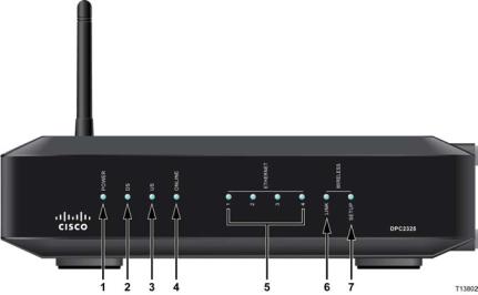
The front panel of your residential gateway provides LED status indicators that indicate how well and at what state your residential gateway is operating. See Front Panel LED Status Indicator Functions (on page 106), for more information on front panel LED status indicator functions.
Model DPC2325
1POWER—ON, power is applied to the wireless residential gateway
2DS—ON, the wireless residential gateway is receiving data from the cable network
3US—ON, the wireless residential gateway is sending data to the cable network
4ONLINE—ON, the wireless residential gateway is registered on the network and fully operational
5ETHERNET 1 - 4—ON, a device is connected to one of the Ethernet ports. BLINKING indicates that data is being transferred over the Ethernet connection
6WIRELESS LINK—ON, the Wireless Access Point is operational. BLINKING indicates that data is being transferred over the wireless connection. OFF indicates that the wireless access point has been disabled by the user
7WIRELESS SETUP—OFF (normal condition) wireless setup is not active. BLINKING indicates the user has activated wireless setup to add new wireless clients on the wireless network
12 |
4024320 Rev A |
Back Panel Description
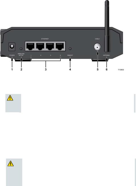
Back Panel Description
The following illustrations show the description and function of the back panel components on the DPC/EPC2325.
External Power Supply Model
Model DPC/EPC2325
1POWER—Connects the residential gateway to the power adapter that is provided with your residential gateway
CAUTION:
Avoid damage to your equipment. Only use the power supply that is provided with your residential gateway.
2WIRELESS SETUP—Pressing this switch initiates wireless setup, this feature allows the user to add new Wi-Fi Protected Setup (WPS) compliant wireless clients to the home network
3ETHERNET—Four RJ-45 Ethernet ports connect to the Ethernet port on your PC or your home network
4REBOOT—A momentary pressing (1-2 seconds) of this switch reboots the residential gateway. Pressing the switch for more than ten seconds causes a reset-to-factory-default of all settings and then reboots the gateway
CAUTION:
The Reboot button is for maintenance purposes only. Do not use unless instructed to do so by your service provider. Doing so may cause you to lose any cable modem settings you have selected.
5CABLE—F-connector connects to an active cable signal from your service provider
6ANTENNA—Connection for external 802.11 antenna
4024320 Rev A |
13 |
Where Is the Best Location for My DOCSIS Residential Gateway?
Where Is the Best Location for My DOCSIS Residential Gateway?
The ideal location for your residential gateway is where it has access to outlets and other devices. Think about the layout of your home or office, and consult with your service provider to select the best location for your residential gateway. Read this user guide thoroughly before you decide where to place your residential gateway.
Consider these recommendations:
Position your PC and residential gateway so that they are located near an AC power outlet.
Position your PC and residential gateway so that they are located near an existing cable input connection to eliminate the need for an additional cable outlet. There should be plenty of room to guide the cables away from the modem and the PC without straining or crimping them.
Airflow around the residential gateway should not be restricted.
Choose a location that protects the residential gateway from accidental disturbance or harm.
14 |
4024320 Rev A |
How Do I Mount the Modem on a Wall? (Optional)
How Do I Mount the Modem on a Wall? (Optional)
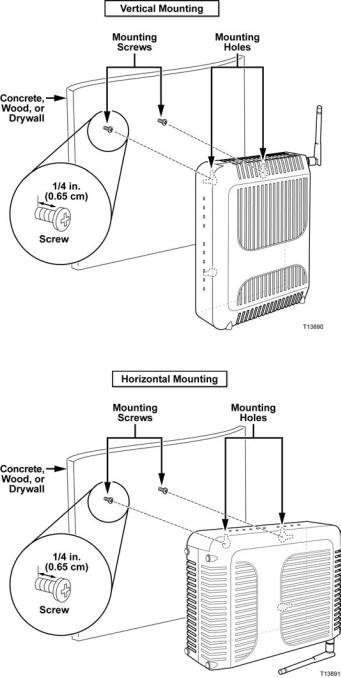
You can mount the residential gateway on a wall using two wall anchors, two screws, and the mounting slots located on the unit. The modem can be mounted vertically or horizontally.
Before You Begin
Before you begin, choose an appropriate mounting place. The wall can be made of cement, wood, or drywall. The mounting location should be free of obstructions on all sides, and the cables should be able to easily reach the residential gateway without strain. Leave sufficient clearance between the bottom of the residential gateway and any flooring or shelving underneath to allow access to cabling. In addition, leave enough slack in all cables so that the residential gateway can be removed for any required maintenance without disconnecting the cables. Also, verify that you have the following items:
Two wall anchors for #8 x 1-inch screws
Two #8 x 1-inch pan head sheet metal screws
Drill with a 3/16-in. wood or masonry bit, as appropriate for the wall composition
A copy of the wall-mounting illustrations shown on the following pages
4024320 Rev A |
15 |
How Do I Mount the Modem on a Wall? (Optional)
Mount the modem as shown in one of the following illustrations.
16 |
4024320 Rev A |
How Do I Mount the Modem on a Wall? (Optional)
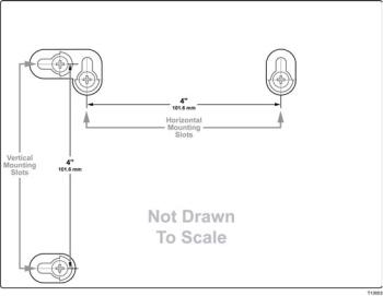
Location and Dimensions of the Wall-Mounting Slots
The following illustration shows the location and dimensions of the wall-mounting slots on the bottom of the modem. Use the information on this page as a guide for mounting your modem to the wall.
Mounting the Residential Gateway on a Wall
1 Using a drill with a 3/16-inch bit, drill two holes at the same height and 4 inches apart.
Note: The preceding graphic illustrates the location of the mounting holes on the back of the residential gateway.
2Are you mounting the residential gateway into a drywall or concrete surface where a wooden stud is available?
If yes, go to step 3.
If no, drive the anchor bolts into the wall, and install the mounting screws into the anchor bolts; leave a gap of about 1/4-inch between the screw head and the wall. Then, go to step 4.
3Install the mounting screws into the wall; leave a gap of about 1/4-inch between the screw head and the wall. Then, go to step 4.
4Verify that no cables or wires are connected to the residential gateway.
5Lift the residential gateway into position. Slip the large end of both mounting slots (located in the back of the residential gateway) over the mounting screws, and then slide the residential gateway down until the narrow end of the keyhole slot contacts the screw shaft.
Important: Verify that the mounting screws securely support the residential gateway before you release the unit.
4024320 Rev A |
17 |
What Are the System Requirements for Internet Service?
What Are the System Requirements for Internet Service?
To ensure that your residential gateway operates efficiently for high-speed Internet service, verify that all of the Internet devices on your system meet or exceed the following minimum hardware and software requirements.
Note: You will also need an active cable input line and an Internet connection.
Minimum System Requirements for a PC
A PC with a Pentium MMX 133 processor or greater
32 MB of RAM
Web browsing software
CD-ROM drive
Minimum System Requirements for Macintosh
MAC OS 7.5 or later
32 MB of RAM
System Requirements for an Ethernet Connection
A PC with Microsoft Windows 2000 operating system (or later) with TCP/IP protocol installed, or an Apple Macintosh computer with TCP/IP protocol installed
An active 10/100BASE-T Ethernet network interface card (NIC) installed
18 |
4024320 Rev A |
How Do I Subscribe to High-Speed Internet Service?
How Do I Subscribe to High-Speed Internet Service?
Before you can use your residential gateway, you need to have a high-speed Internet access account. If you do not have a high-speed Internet access account, you need to set up an account with your local service provider. Choose one of the two options in this section.
I Do Not Have a High-Speed Internet Access Account
If you do not have a high-speed Internet access account, your service provider will set up your account and become your Internet Service Provider (ISP). Internet access enables you to send and receive e-mail, access the World Wide Web, and receive other Internet services.
You will need to give your service provider the following information:
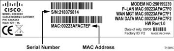
The serial number of the modem
The Media Access Control (MAC) address of the modem
These numbers appear on a bar code label located on the residential gateway. The serial number consists of a series of alphanumeric characters preceded by S/N. The MAC address consists of a series of alphanumeric characters preceded by CM MAC. The following illustration shows a sample bar code label.
Write down these numbers in the space provided here.
Serial Number _______________________
MAC Address ________________________
I Already Have an Existing High-Speed Internet Access Account
If you have an existing high-speed Internet access account, you must give your service provider the serial number and the MAC address of the residential gateway. Refer to the serial number and MAC address information listed previously in this section.
Note: You may not be able to continue to use your existing e-mail account with your residential gateway. Contact your service provider for more information.
4024320 Rev A |
19 |
How Do I Connect My Devices to Use the Internet?
How Do I Connect My Devices to Use the Internet?
You can use your residential gateway to access the Internet, and you can share that Internet connection with other Internet devices in your home or office. Sharing one connection among many devices is called networking.
Connecting and Installing Internet Devices
You must connect and install your residential gateway to access the Internet. Professional installation may be available. Contact your local service provider for further assistance.
To connect devices
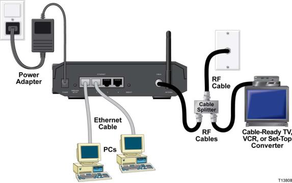
The following diagram illustrates one of the various networking options that are available to you.
20 |
4024320 Rev A |
How Do I Connect My Devices to Use the Internet?
Connecting the Modem for High-Speed Data Service
WARNING:
To avoid personal injury or damage to your equipment, follow these steps in the exact order shown.
Wiring and connections must be properly insulated to prevent electrical shock.
Disconnect power from the residential gateway before attempting to connect to any device.
6Power off your PC and other networking device; then, unplug them from the power source.
7Connect the active RF coaxial cable from your service provider to the coax connector labeled CABLE on the back of the gateway.
Note: To connect a TV, DHCT, set-top box, or VCR from the same cable connection, you will need to install a cable signal splitter (not included).
8Locate the yellow Ethernet cable. Connect one end of the Ethernet cable to the Ethernet port on your PC and then connect the other end to one of the ETHERNET ports on the gateway (any Ethernet port can be used). The Ethernet ports are yellow connectors on the back panel of the gateway.
9Connect additional Ethernet network devices in a similar fashion to any unused Ethernet ports on the back of the gateway.
Note: To install more Ethernet devices than ports provided, use an external multi-port Ethernet switch(s).
10Locate the AC power adapter provided with your gateway. Insert the barrel shaped DC power connector (attached by a thin pair of wires to the AC power adapter) into the black POWER connector on the back of the residential gateway. Then, plug the AC power cord into an AC outlet to power-up the gateway. The residential gateway will perform an automatic search to locate and sign on to the broadband data network. This process may take up 2-5 minutes. The modem will be ready for use when the POWER, DS, US and ONLINE LEDs on the front panel of the gateway stop blinking and remain ON continuously.
11Plug in and power on your PC and other home network devices. The ETHERNET LEDs on the gateway corresponding to the connected devices should be ON or BLINKING.
12Once the gateway is online, most Internet devices will have immediate Internet access.
Note: If your PC does not have Internet access, refer to How Do I Configure TCP/IP Protocol? (on page 100) for information on how to configure your PC for Internet access. For Internet devices other than PCs, refer to the DHCP or IP Address configuration section of the User Guide or Operations Manual for those devices.
4024320 Rev A |
21 |
How Do I Configure My DOCSIS Residential Gateway?
How Do I Configure My DOCSIS Residential Gateway?
To configure your residential gateway, you must first access the WebWizard configuration pages. This section provides detailed instructions and procedures for accessing the WebWizard pages and for configuring your residential gateway to operate correctly. This section also presents examples and descriptions of each WebWizard configuration page. Use the WebWizard pages to customize your residential gateway to your needs rather than using the default settings. The WebWizard pages in this section are organized in the order shown on the Setup page.
Important: The WebWizard pages and the examples shown in this section are for illustration purposes only. Your pages may differ from the pages shown in this guide.
Note: If you are not familiar with the network configuration procedures detailed in this section, contact your service provider before you attempt to change any of the residential gateway default settings.
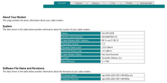
About Your Modem Page Example
The following illustration is an example of the About Your Modem page.
22 |
4024320 Rev A |
How Do I Configure My DOCSIS Residential Gateway?
Accessing the Residential Gateway
You must access the WebWizard in order to configure the residential gateway. To gain access to the WebWizard, use the web browser on the PC attached to the gateway and complete the following steps.
1Open the web browser on your PC.
2Type the following IP address and then select Go: http://192.168.0.1.
3The web browser accesses the WebWizard and displays the default About Your Modem page. This page displays information about your cable modem along with a series of tabs for accessing other WebWizard configuration and operation features.
About Your Modem Page Description
The following table provides a description of each field within the About Your Modem page.
Field Name |
Description |
Name |
The name of the residential gateway |
|
|
Modem Serial Number |
A unique sequential series of alphanumeric |
|
characters provided to every modem during |
|
manufacturing |
|
|
Cable Modem MAC |
A unique alphanumeric address for the cable |
Address |
modem coaxial interface, which is used to connect |
|
to the cable modem termination system (CMTS) at |
|
the headend. A media access control (MAC) |
|
address is a hardware address that uniquely |
|
identifies each node of a network |
|
|
Hardware Version |
Identifies the revision of the circuit board design |
|
|
Receive Power Level |
The input level of the downstream CMTS carrier |
|
|
Transmit Power Level |
Indicates the upstream power level |
|
|
4024320 Rev A |
23 |
How Do I Configure My DOCSIS Residential Gateway?
Field Name |
Description |
|
Cable Modem Status |
Lists one of the following possible current states of |
|
|
the modem: |
|
|
|
other |
|
|
notReady |
|
|
notSynchronized |
|
|
phySynchronized |
|
|
usParametersAcquired |
|
|
rangingComplete |
|
|
ipComplete |
|
|
todEstablished |
|
|
securityEstablished |
|
|
psrsmTransferComplete |
|
|
registrationComplete |
|
|
operational |
|
|
accessDenied |
|
|
|
Vendor |
The name of the manufacturer |
|
|
|
|
Boot Revision |
Identifies the boot revision code version |
|
Software File Name and Revisions Section
Field Name |
Description |
Firmware Name |
Identifies the name of the firmware |
|
|
Software Revision |
Identifies the revision version of the firmware |
24 |
4024320 Rev A |
How Do I Configure My DOCSIS Residential Gateway?
Setting Configuration Options
Use the Setup page to access the various configuration options for the residential gateway. Detailed descriptions of each configuration option follow later in this guide.
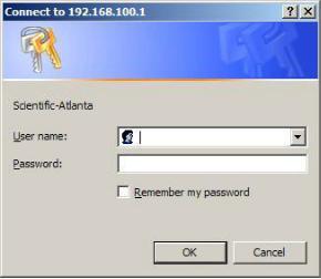
Important: After you access the WebWizard by typing the 192.168.0.1 IP address into your web browser while the gateway is online, an authentication window similar to the following window opens:
Enter your password; then, click OK to continue to the Setup page.
First Time Users
The gateway ships from the factory without a factory-assigned or default password.
Leave the user name and the password fields blank. Then click OK to be directed to the Password Settings page.
Note: You will be prompted to set up a password. We highly recommend that you set up a password to prevent unauthorized access to the settings of the gateway. If you choose not to enter a password, this page will appear each time you access the setup pages. See Configuring Your Password Settings (on page 30) for assistance in setting up your password. If you choose not to use password security, click the Setup tab at the top of the Password Settings page to continue.
4024320 Rev A |
25 |
How Do I Configure My DOCSIS Residential Gateway?
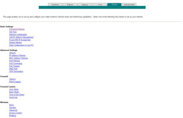
Setup Page
The following illustration is an example of the Setup page.
Setup Page Section Headings
The Setup page is divided into the following section headings:
Basic Settings
Advanced Settings
Firewall
Parental Control
Wireless
In the Setup page, click the selections listed within these sections to access the WebWizard page for that selection. A description of the selections available in each section follows next.
26 |
4024320 Rev A |
How Do I Configure My DOCSIS Residential Gateway?
Basic Settings
The following table provides a description of the pages available from within the Basic Settings section of the Setup page.
Field Name |
Description |
Password Settings |
Use this link to set or modify your password settings |
|
|
Set Time |
Use this link to enable or disable time synchronization |
|
by Network Time protocol |
|
|
Network Configuration |
Use this link to enter or modify the basic settings for |
|
your network |
|
|
LAN IP Address |
Use this link to configure how Internet protocol (IP) |
Management |
addresses are assigned and managed in your network |
|
|
Fixed CPE IP Assignment |
Use this link to reserve IP addresses in the DHCP pool |
|
that will be used as static IP addresses in your local |
|
network. |
|
|
Restart Modem |
Use this link to restart your residential gateway |
|
|
Save Configuration to |
Use this link to save your cable modem RG |
your PC |
configuration to your local PC and to restore the RG |
|
configuration to your residential gateway, if necessary |
Advanced Settings
The following table provides a description of the pages available from within the Advanced Settings section of the Setup page.
|
Field Name |
Description |
|
|
Options |
Use this link to enable or disable advanced features |
|
|
|
on your network |
|
|
|
|
|
|
IP Address Filtering |
Use this link to configure IP address filters. These |
|
|
|
filters prevent designated IP addresses from |
|
|
|
accessing the Internet |
|
|
|
|
|
|
MAC Address Filtering |
Use this link to configure MAC address filters. |
|
|
|
These filters prevent designated MAC addresses |
|
|
|
from accessing the Internet |
|
|
|
|
|
|
Port Filtering |
Use this link to configure transmission control |
|
|
|
protocol (TCP) and user datagram protocol (UDP) |
|
|
|
port filters. These filters prevent a range of |
|
|
|
TCP/UDP ports from accessing the Internet |
|
|
|
|
|
|
Port Forwarding |
Use this link to configure port forwarding for local |
|
|
|
IP addresses. Port forwarding allows you to run a |
|
|
|
server on the local area network (LAN) by |
|
|
|
specifying the mapping of TCP/UDP ports to local |
|
|
|
PCs or to the IP address of other devices. This is a |
|
|
|
static setting that holds the ports open at all times |
|
|
|
|
|
4024320 Rev A |
27 |
||
How Do I Configure My DOCSIS Residential Gateway?
Field Name |
Description |
Port Triggers |
Use this link to configure TCP/UDP port triggers. |
|
Port triggering is similar to port forwarding, but is |
|
a dynamic function. In other words, the ports are |
|
not held open, and the ports close if no outgoing |
|
data is detected on the selected ports for a period |
|
of 10 minutes |
|
|
DMZ Host |
Use this link to configure an IP address that is |
(Demilitarized Zone) |
visible to the wide area network (WAN). DMZ |
|
hosting is commonly referred to as “exposed host,” |
|
and allows you to specify the “default” recipient of |
|
WAN traffic that Network Address Translation |
|
(NAT) is unable to translate to a known local PC |
|
A DMZ is used by a company that wants to host its |
|
own Internet services without sacrificing |
|
unauthorized access to its private network. DMZ |
|
allows one IP address to be unprotected while |
|
others remain protected. The DMZ is located |
|
between the Internet and an internal network's line |
|
of defense that is a combination of firewalls and |
|
bastion hosts |
|
Typically, the DMZ contains devices accessible to |
|
Internet traffic, such as web (HTTP) servers, FTP |
|
servers, SMTP (e-mail) servers, and domain name |
|
system (DNS) servers |
|
|
VPN Termination |
Use this link to create, configure, and control |
|
Virtual Private Network (VPN) protocols and |
|
manage Internet Protocol Security (IPsec) VPN |
|
tunnels. |
Firewall
The following table provides a description of the pages available from within the Firewall section of the Setup page.
Field Name |
Description |
Options |
Use this link to configure webpage filtering and |
|
firewall protection |
|
|
Event Logging |
Use this link to access the firewall event log and to |
|
enter your e-mail address in order to receive |
|
e-mail alerts related to firewall attacks by hackers |
28 |
4024320 Rev A |
How Do I Configure My DOCSIS Residential Gateway?
Parental Control
The following table provides a description of the pages available from within the Parental Control section of the Setup page.
Field Name |
Description |
User Setup |
Use this link to add or delete user profiles and to apply |
|
access rules to those users |
|
|
Basic Rules |
Use this link to setup access rules that block certain |
|
Internet content and certain websites |
|
|
Time of Day Rules |
Use this link to configure web access filters to block all |
|
Internet traffic to and from specific network devices |
|
based on time of day settings that you select |
|
|
Local Log |
Use this link to view events captured by Parental |
|
Control event log feature |
Wireless
The following table provides a description of the pages available from within the Wireless section of the Setup page.
Field Name |
Description |
Basic |
Use this link to configure your wireless access point |
|
(WAP) parameters, including service set identifier |
|
(SSID) and channel number |
|
|
Security |
Use this link to configure your WAP authentication |
|
and data encryption. Using encryption and |
|
authentication prevents unauthorized access to your |
|
wireless devices |
|
|
Advanced |
Use this link to configure your WAP data rates and |
|
wireless fidelity (Wi-Fi) thresholds |
|
|
Access Control |
Use this link to configure the WAP to restrict access |
|
to only selected wireless client devices. Authorized |
|
clients are selected by MAC address. Use this link to |
|
select Open System or Share Key authentication and |
|
to enable and disable broadcast of the WAP SSID |
|
|
Bridging |
Use this link to configure a Wireless Distribution |
|
System (WDS) in our network |
4024320 Rev A |
29 |
How Do I Configure My DOCSIS Residential Gateway?
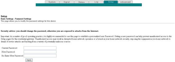
Configuring Your Password Settings
Use the Basic Settings - Password Settings page to set up or modify a password to restrict unauthorized persons from accessing to your residential gateway settings. Click Password Settings in the Basic Settings section of the Setup page to access the Password Settings page.
Notes:
Your gateway modem comes from the factory with no password enabled. We highly recommend that you set up a user password to prevent unauthorized users from modifying the settings of your network.
If you do choose to set up a password, use a password that you can easily remember. Do not forget your password.
Setup Basic Settings - Password Settings
The following illustration is an example of the Basic Settings - Password Settings page.
To set up your password
1To set up your password, type your current password in the Current Password field.
2Type your new password in the New Password field, and then re-enter your new password in the Re-Enter New Password field.
3Click Apply to save your password. A webpage appears to indicate that you have successfully set your password.
4Click on the Setup tab to proceed with setting up your gateway. The User Name and Password dialogue box appears as shown below.
5Enter your password; then, click LOGIN to continue to the main Setup page.
30 |
4024320 Rev A |
Loading...