


 Loading...
|
|
|
Customer Order Number: |
DOC-781812= |
|
Documentation Part Number: |
78-1812-10 |
|
Fast Ethernet Interface Processor (FEIP)
Installation and Configuration
Product Numbers: CX-FEIP-1TX=, CX-FEIP-2TX=, CX-FEIP-1FX=, CX-FEIP-2FX=
This configuration note is a standalone publication that provides instructions for installing and configuring the Fast Ethernet Interface Processor (FEIP) in all Cisco 7000 series routers and Cisco 7500 series routers. (For specific compatibility requirements, refer to the section “Software and Hardware Prerequisites,” on page 3.)
Note For convenience throughout this publication, FEIP-1TX, FEIP-2TX, FEIP-1FX, and
FEIP-2FX are referred to as FEIP, with specific differences clearly noted.
Included in this configuration note are steps for FEIP hardware installation and cable connection, and basic FEIP configuration steps and examples. A table of contents is included so you can more easily find what you need.
For additional descriptions of interface subcommands and configuration options available for Fast Ethernet (FE) interfaces, refer to the appropriate Cisco IOS software configuration and command reference publications listed in the section “If You Need More Information” on page 2.
Corporate Headquarters
Cisco Systems, Inc.
170 West Tasman Drive
San Jose, CA 95134-1706
USA
Copyright © 1995–2002 |
|
Cisco Systems, Inc. |
1 |
All rights reserved. |

Document Contents
Document Contents
This publication includes the following sections:
•
•
•
•
•
•
•
If You Need More Information
Installation Prerequisites on page 3
What Is the FEIP?, page 15
FEIP Installation, page 21
Configuring the Fast Ethernet Interfaces* on page 28
Upgrading FEIP Microcode, page 37
Cisco.com on page 41
If You Need More Information
The Cisco IOS software running your router contains extensive features and functionality. For information on Cisco IOS software and for general installation and maintenance information for your router, use the following resources:
•Cisco Documentation CD-ROM package
Cisco documentation and additional literature are available in a CD-ROM package, which ships with your product. The Documentation CD-ROM, a member of the Cisco Connection Family, is updated monthly; therefore, it might be more up to date than printed documentation. To order additional copies of the Documentation CD-ROM, contact your local sales representative or call customer service. The CD-ROM package is available as a single package or as an annual subscription.
•For Cisco IOS software configuration information and support, refer to the modular configuration and modular command reference publications in the Cisco IOS software configuration documentation set that corresponds to the software installed on your Cisco hardware. You can also refer to the Cisco IOS software release notes for the version of software you are using on your hardware.
•For hardware installation and maintenance information on the Cisco 7500 series routers, refer to the Cisco 7500 Series Installation and Configuration Guide that shipped with your Cisco 7500 series router.
•For hardware installation and maintenance information on the Cisco 7000 series routers, refer to the Cisco 7000 Hardware Installation and Maintenance manual and the Cisco 7000 User Guide, or to the Cisco 7010 Hardware Installation and Maintenance manual and the Cisco 7010 User Guide, which shipped with your Cisco 7000 or Cisco 7010 router, respectively.
Note You can access Cisco IOS software documentation and hardware installation and maintenance documentation on the World Wide Web at http://www.cisco.com, http://www-china.cisco.com, http://www-europe.cisco.com.
If you are reading Cisco documentation on the World Wide Web, you can submit comments electronically. Click Feedback on the toolbar, and then select Documentation. After you complete the form, click Submit to send it to Cisco. We appreciate your comments.
2 Fast Ethernet Interface Processor (FEIP) Installation and Configuration

Installation Prerequisites
•To obtain information about documentation, refer to the following:
—World Wide Web on page 40
—Documentation CD-ROM on page 40
—Ordering Documentation on page 40
—Documentation Feedback on page 40
—Cisco.com on page 41
—Technical Assistance Center on page 41
—The Cisco Information Packet that shipped with your router.
Installation Prerequisites
This section provides software and hardware prerequisites, a list of parts and tools you will need to perform the installation, and safety and ESD-prevention guidelines to help you to avoid injury and damage to the equipment. It also provides a detailed description of the OIR function to help you perform online installation successfully and avoid error message and system restarts. If you are installing a new FEIP, be sure to review the equipment descriptions and distance limitations in the section “FEIP Receptacles, Cables, and Pinouts” on page 17.
Software and Hardware Prerequisites
The FEIP with 100BASE-TX port adapters operates with the CxBus and CyBus and requires that the host Cisco 7000 series router is running Cisco IOS Release 10.3(5), or later, and the host Cisco 7500 series routers are running Cisco IOS Release 10.3(6) or later.
The FEIP with 100BASE-FX port adapters operates with the CxBus and CyBus and requires that the host Cisco 7000 family router is running Cisco IOS Release 10.3(13), or later, Release 11.0(10), or later, or Release 11.1(5), or later.
Note The latest FEIP microcode images are available via anonymous File Transfer Protocol (FTP) from /ftp/feip-fx at ftp.cisco.com. Detailed information about the latest FEIP microcode images can be found in the ASCII file feip.readme.txt, which is also available via FTP from ftp.cisco.com in the directory /ftp/feip-fx/. This ASCII file includes information and instructions on how to get the current FEIP microcode image. To access Cisco IOS images, refer to the section “Cisco.com” on page 41 at the end of this publication.
Caution If you use the FEIP with a single port adapter, you must have the port adapter in slot 0 for the FEIP to function properly. A single port adapter in slot 1 will not be recognized by the system.
Note Each FE interface on an FEIP can be configured at 100 Mbps, half duplex or full duplex, for a maximum aggregate bandwidth of 200 Mbps.
Caution To prevent oversubscribing the FEIP, we recommend that you do not operate both FE interfaces on an FEIP in full-duplex mode.
Fast Ethernet Interface Processor (FEIP) Installation and Configuration 3

Installation Prerequisites
Each FEIP is a fixed configuration; therefore, individual port adapters are not available as spare parts and are not field-replaceable or removable. The entire FEIP assembly is treated as a field-replaceable unit (FRU). Do not attempt to remove an FEIP’s port adapter and replace it with another. Do not attempt to simultaneously operate 100BASE-TX and 100BASE-FX port adapters on the same FEIP.
List of Parts and Tools
You need the following tools and parts to install or upgrade an FEIP. If you need additional equipment, contact a service representative for ordering information.
•CX-FEIP-1TX(=), CX-FEIP-2TX(=), CX-FEIP-1FX(=), or CX-FEIP-2FX(=), and at least one available interface processor slot in your Cisco 7000 series or Cisco 7500 series router (For specific compatibility requirements, refer to the section “Software and Hardware Prerequisites” on page 3.)
•Cables appropriate for the interfaces on your FEIP; Cisco Systems does not supply Category 5 UTP RJ-45 cables, MII cables, or SC-type cables; these cables are available commercially. (For specific cable requirements, refer to the section “FEIP Receptacles, Cables, and Pinouts” on page 17.)
Caution Before you attach an MII transceiver to an MII receptacle on your FEIP, ensure that your MII transceiver responds to physical sublayer (PHY) address 0 per section 22.2.4.4. “PHY Address” of the IEEE 802.3u specification; otherwise, interface problems might result. Confirm that this capability is available on your MII transceiver with the transceiver's vendor or in the transceiver's documentation. If a selection for “Isolation Mode” is available, we recommend you use this setting (if no mention is made of “PHY addressing”).
Caution To prevent system problems, do not simultaneously connect cables to the RJ-45 (or SC) and MII receptacles on a single FEIP interface. Each interface (100BASE-FX or 100BASE-TX) can have either an MII attachment or an RJ-45 (or SC) attachment, but not both. The MII and RJ-45 (or SC) receptacles represent two physical connection options for one interface.
•Number 1 Phillips and a 3/16-inch, flat-blade screwdriver
•Your own ESD-prevention equipment or the disposable grounding wrist strap included with all upgrade kits, FRUs, and spares
Safety Guidelines
Following are safety guidelines that you should follow when working with any equipment that connects to electrical power or telephone wiring.
Electrical Equipment Guidelines
Follow these basic guidelines when working with any electrical equipment:
•Before beginning any procedures requiring access to the chassis interior, locate the emergency power-off switch for the room in which you are working.
•Disconnect all power and external cables before moving a chassis
•Do not work alone when potentially hazardous conditions exist.
•Never assume that power has been disconnected from a circuit; always check.
4 Fast Ethernet Interface Processor (FEIP) Installation and Configuration

Safety Guidelines
•Do not perform any action that creates a potential hazard or makes the equipment unsafe.
•Carefully examine your work area for possible hazards such as moist floors, ungrounded power extension cables, and missing safety grounds.
Telephone Wiring Guidelines
Use the following guidelines when working with any equipment that is connected to telephone wiring or to other network cabling:
•
•
Never install telephone wiring during a lightning storm.
Never install telephone jacks in wet locations unless the jack is specifically designed for wet locations.
•Never touch uninsulated telephone wires or terminals unless the telephone line has been disconnected at the network interface.
•Use caution when installing or modifying telephone lines.
Preventing Electrostatic Discharge Damage
Electrostatic discharge (ESD) damage, which can occur when electronic cards or components are improperly handled, results in complete or intermittent failures.
Use the following guidelines for preventing ESD damage:
•Always use an ESD wrist or ankle strap and ensure that it makes good skin contact.
•Connect the equipment end of the strap to an unfinished chassis surface.
•When installing a component, use any available ejector levers or captive installation screws to properly seat the bus connectors in the backplane.
•When removing a component, use any available ejector levers or captive installation screws to release the bus connectors from the backplane or midplane.
•Handle carriers by available handles or edges only; avoid touching the printed circuit boards or connectors.
•Place a removed component board-side-up on an antistatic surface or in a static shielding container; otherwise, immediately place it in a static shielding container.
•Avoid contact between the printed circuit boards and clothing. The wrist strap only protects components from ESD voltages on the body; ESD voltages on clothing can still cause damage.
•Never attempt to remove the printed circuit board from the metal carrier.
Caution For safety, periodically check the resistance value of the antistatic strap. The measurement should be between 1 and 10 megohms.
Fast Ethernet Interface Processor (FEIP) Installation and Configuration 5

Installation Prerequisites
Guidelines for Interface Processor Installation and Removal
This section describes mechanical functions of system components, emphasizes the importance of following correct procedures to avoid unnecessary board failures, and is for background only; specific procedures follow in the section “FEIP Installation” on page 21.
You can remove and replace interface processors while the system is operating; you do not need to notify the software or reset the system power. This functionality enables you to add, remove, or replace interface processors with the system online, which provides a method that is seamless to end users on the network, maintains all routing information, and ensures session preservation.
After an interface processor is reinstalled, the system brings on line only interfaces that match the current configuration and were previously configured as up; all others require that you configure them with the configure command.
Caution The system can indicate a hardware failure if you do not follow proper procedures. Remove or insert only one interface processor at a time. Allow at least 15 seconds for the system to complete the preceding tasks before removing or inserting another interface processor. Disrupting the sequence before the system completes its verification can cause the system to interpret hardware failures.
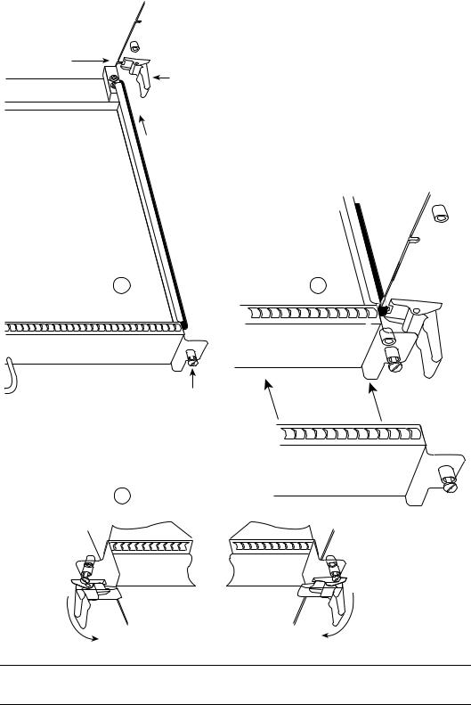
Cisco 7000 series and Cisco 7500 series routers have ejector levers located on the ends of the interface processor slots. (See Figure 1a.) The function of the ejector levers is to align and seat the interface processor connectors in the backplane. Failure to use the ejector levers and insert the interface processor properly can disrupt the order in which connector pins make contact with the backplane.
Follow the FEIP installation and removal instructions carefully, and review the following examples of incorrect insertion practices and their results:
•Using the handle to force the interface processor all the way into the slot can pop the ejector levers out of their springs. If you then try to use the ejector levers to seat the interface processor, the first layer of pins (which are already mated to the card or interface processor) can disconnect and then remate with the backplane, which the system interprets as a board failure.
•Using the handle to force or slam the interface processor all the way into the slot can damage the pins on the board connectors if they are not aligned properly with the backplane.
•When using the handle (rather than the ejector levers) to seat the interface processor in the backplane, you might need to pull the interface processor back out and push it in again to align it properly. Even if the backplane pins are not damaged, the pins mating with and disconnecting from the card or interface processor might cause the system to interpret a board failure. Using the ejector levers ensures that the board connector mates with the backplane in one continuous movement.
•Using the handle to insert or remove an interface processor, or failing to push the ejector levers fully against the interface processor, can leave some (not all) of the connector pins mated to the card or interface processor, a state which hangs the system. Using the ejector levers and making sure that they are pushed fully into position ensures that all three layers of pins are mated with (or free from) the backplane.
Use the ejector levers when removing an interface processor to ensure that the backplane connector pins disconnect from the interface processor in the sequence expected by the system. Any interface processor that is only partially connected to the backplane can hang the bus. Steps for correctly performing OIR are included with the following procedures for installing and removing the FEIP.
6 Fast Ethernet Interface Processor (FEIP) Installation and Configuration
|
Guidelines for Interface Processor Installation and Removal |
Figure 1 |
Ejector Levers/Captive Installation Screws on the FEIP (Horizontal |
|
Orientation Shown) |
Interface processor |
|
card slot |
Ejector |
|
|
|
lever |
 Interface processor card carrier guide (black)
a |
b |
Captive installation screw
c
H1984
Note The FEIP is oriented horizontally in the Cisco 7010 and Cisco 7505 and vertically in the
Cisco 7000, Cisco 7507, and Cisco 7513.
Fast Ethernet Interface Processor (FEIP) Installation and Configuration 7

Installation Prerequisites
Microcode Overview
The FEIP microcode (firmware) is an image that provides card-specific software instructions. A programmable read-only memory (PROM) device on the FEIP contains a default microcode boot image that assists the system in finding and loading the microcode image from the Cisco IOS software bundle or Flash memory. The router supports downloadable microcode, which allows you to upgrade microcode versions by downloading new microcode images, storing them in system Flash memory, and instructing the system to load its image from Flash. You can store multiple images for an interface type and, with a configuration command, instruct the system to load any one of them or the default microcode image. The microcode boot image in the PROM initializes the FEIP and then assists downloading the FEIP microcode image. All interfaces of the same type (FEIP, and so on) load the same microcode image, either from the microcode image bundled with the Cisco IOS software or from an image stored in system Flash. Although multiple microcode versions for a specific interface type can be stored concurrently in Flash, only one image can load at startup.
The show controllers cbus command displays the currently loaded and running microcode version for each interface processor, and FEIP. The show startup-config EXEC command shows the current system instructions for loading microcode at startup.
Software and interface processor microcode images are carefully optimized and bundled to work together. Overriding the bundle can result in system incompatibilities. We recommend that you use the microcode included in the software bundle. For a complete description of microcode and downloading procedures, refer to the section “Upgrading FEIP Microcode” on page 37.
Fast Ethernet Overview
The term Ethernet is commonly used for all carrier sense multiple access/collision detection (CSMA/CD), local-area networks (LANs) that generally conform to Ethernet specifications, including Fast Ethernet under IEEE 802.3u.
Note 100BASE-TX is intended for Environment A, and 100BASE-FX is intended for
Environment B.
IEEE 802.3u is well suited to applications where a local communication medium must carry sporadic, occasionally heavy traffic at high peak data rates. Stations on a CSMA/CD LAN can access the network at any time. Before sending data, the station listens to the network to see if it is already in use. If it is, the station waits until the network is not in use, then transmits; this is half-duplex operation.
A collision occurs when two stations listen for network traffic, hear none, and transmit very close to simultaneously. When this happens, both transmissions are damaged, and the stations must retransmit. The stations detect the collision and use backoff algorithms to determine when they should retransmit. Both Ethernet and IEEE 802.3u are broadcast networks, which means that all stations see all transmissions. Each station must examine received frames to determine if it is the intended destination and, if it is, to pass the frame to a higher protocol layer for processing.
IEEE 802.3u specifies the following different physical layers for 100BASE-T:
•100BASE-TX—100BASE-T, half and full duplex over Category 5 unshielded twisted-pair (UTP), Electronics Industry Association/Telecommunications Industry Association [EIA/TIA]-568-compliant cable
•100BASE-FX—100BASE-T, half and full duplex over optical fiber
8 Fast Ethernet Interface Processor (FEIP) Installation and Configuration

IEEE 802.3u 100BaseT Specifications
•100BASE-T4—100BASE-T, half and full duplex over Category 3, 4, or 5 UTP or shielded twisted-pair (STP) cabling with four pairs; also called 4T+ or T2, which is 2-pair UTP over Category 3 cable.
Each physical layer protocol has a name that summarizes its characteristics in the format speed/signaling method/segment length, where speed is the LAN speed in megabits per second (Mbps), signaling method is the signaling method used (either baseband or broadband), and segment length is typically the maximum length between stations in hundreds of meters. Therefore, 100BASE-T specifies a 100-Mbps, baseband LAN with maximum network segments of 100 meters (or 400 meters for 100BASE-FX).
IEEE 802.3u 100BaseT Specifications
This section provides specifications for IEEE 802.3u 100BaseT. Table 1-1 provides cabling specifications for 100BaseTX Fast Ethernet transmission over UTP and foil twisted-pair (FTP), and 100BaseFX Fast Ethernet over fiber-optic cables. It also summarizes IEEE 802.3u 100BaseTX and 100BaseFX physical characteristics. Also see Figure 2.
Table 1 |
Specifications and Connection Limits for 100BASE-TX and 100BASE-FX Transmission |
|||
|
|
|
|
|
Parameter |
|
100BASE-TX |
100BASE-FX Multimode |
100BASE-FX Single Mode |
|
|
|
|
|
Cable specification |
|
Category 5 1 UTP2, 22 to 24 AWG |
62.5/125 multimode optical fiber |
9/125 micron single-mode optical fiber |
Maximum segment |
100 m |
412 m |
N/A |
|
length (half-duplex)3 |
|
|
|
|
Maximum segment |
100 m |
2000 m |
10,000 m |
|
length (full-duplex)3 |
|
|
|
|
Maximum network |
200 m |
272 m |
N/A |
|
length (half-duplex, one |
|
|
|
|
repeater)4 |
|
|
|
|
Data rate |
|
100 Mbps |
100 Mbps |
100 Mbps |
|
|
|
|
|
Signaling method |
|
4B/5B block coded, scrambled, with |
4B/5B block coded, with NRZI |
4B/5B block coded, with NRZI line |
|
|
MLT-3 line coding |
line coding |
coding |
|
|
|
|
|
Connector |
|
SC-type: dual simplex or single |
RJ-45 (ISO/IEC 60603-7:-1990 |
Single mode SC-type: dual simplex or |
|
|
duplex for RX and TX |
|
single duplex for RX and TX |
|
|
|
|
|
Topology |
|
Star/hub |
Star/hub |
Star/hub |
|
|
|
|
|
1.EIA/TIA-568 or EIA-TIA-568 TSB-36 compliant.
2.Cisco does not supply Category 5 UTP RJ-45 cables. However, they are available commercially.
3.Data Terminal Equipment (DTE to DTE), see Figure 2.
4.DTE to Repeater to DTE, see Figure 2.
Fast Ethernet Interface Processor (FEIP) Installation and Configuration 9

Installation Prerequisites
Figure 2 Maximum Segment and Network Lengths—100BASE-FX and 100BASE-TX
Maximum segment length, full duplex
100 m TX
DTE*  DTE
DTE
2000 m FX–multimode
Maximum segment length, full duplex
10,000 m FX–single mode
DTE  DTE
DTE
Maximum segment length, half duplex
100 m TX
DTE  DTE 412 m FX
Maximum network length, half duplex
200 m TX
DTE  R
R  DTE (Repeater)
272 m FX**
**Because repeaters have more delay, total network length is shorter.
31703
*DTE = Data Terminal Equipment
What Is the Cisco 7000 Series?
The Cisco 7000 series includes the Cisco 7000 and Cisco 7010 routers. The FEIP operates in the Cisco 7000 series routers. (For software and hardware requirements, refer to the section “Software and Hardware Prerequisites” on page 3.)
Network interfaces reside on modular interface processors, including the FEIP, which are inserted into interface processor slots and provide a direct connection between external networks and the high-speed CxBus in the Cisco 7000 series. The Cisco 7000 series supports any combination of available network interface types.
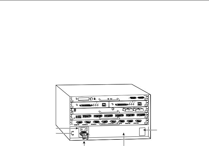
In the 7-slot Cisco 7000 (see Figure 3), slots 0 through 4 are for interface processors including the FEIP.
10 Fast Ethernet Interface Processor (FEIP) Installation and Configuration

What Is the Cisco 7000 Series?
Figure 3 Cisco 7000 (Interface Processor End)
Captive |
|
|
|
|
|
|
|
|
installation screw |
|
|
|
|
|
|
|
|
DC |
|
|
|
|
|
|
|
|
FAIL |
|
|
|
|
|
|
|
|
AC |
|
|
|
|
|
|
|
|
POWER |
|
|
ENABLE |
|
|
|
|
|
|
|
|
|
|
NORMAL |
|
|
|
|
|
|
|
|
|
|
|
|
Upper |
|
|
|
|
|
|
|
|
power supply |
|
|
|
|
|
|
|
|
|
|
|
|
|
|
EJECT |
|
|
I |
|
|
|
|
|
SLOT |
|
|
|
|
|
|
|
|
1 |
|
|
|
|
|
|
|
|
SLOT0 |
|
|
O |
|
|
|
|
|
|
|
|
Captive |
|
|
ENABLE |
|
|
CPU |
HALT |
|
installation screw |
|
|
|
|
|
|
||
|
|
|
|
RESET |
|
|||
|
|
|
|
|
|
|||
DC |
|
|
|
|
|
|
|
|
FAIL |
|
|
|
|
|
|
|
|
AC |
|
|
|
|
|
|
|
|
POWER |
|
|
|
|
|
|
|
|
Lower |
|
|
|
|
|
AUX |
|
|
|
|
|
|
|
. |
|
|
|
power supply |
|
|
|
|
|
|
|
H5288 |
|
|
|
|
|
|
CONSOLE |
SWITCHROUTE |
|
|
|
|
|
|
|
|
||
I |
|
|
|
|
|
|
PROCESSOR |
|
|
|
|
|
|
|
|
|
|
O |
|
|
|
|
|
|
|
|
Interface processor slots |
0 |
1 |
2 |
3 |
4 |
RSP |
RSP |
|
|
|
|
|
|
|
7000 |
7000CI |
|
|
|
|
|
|
|
slot 5 |
slot 6 |
|
In the 5-slot Cisco 7010 (Figure 4), slots 0 through 2) are for interface processors including the FEIP.
Figure 4 Cisco 7010 (Interface Processor End)
Power switch
Chassis ground  screw
screw
|
EJECT |
SLOT |
1 |
0 |
CPU |
HALT |
RESET |
AUX |
NORMAL |
|
|
|
|
|
|
|
. |
|
SLOT |
|
|
|
|
|
||
ENABLE |
ENABLE |
|
ROUTE SWITCH PROCESSOR
CONSOLE |
RSP7000CI slot 4
RSP7000 slot 3
Interface processor slot 2
Interface processor slot 1
Interface processor slot 0
DC OK LED
H5874
Power receptacle |
AC-input power supply |
Fast Ethernet Interface Processor (FEIP) Installation and Configuration 11
Installation Prerequisites
What Is the Cisco 7500 Series?
The Cisco 7500 series includes the Cisco 7505, Cisco 7507, and Cisco 7513 routers. The FEIP operates in the Cisco 7500 series routers. (For software and hardware requirements, refer to the section “Software and Hardware Prerequisites” on page 3.)
Network interfaces reside on modular interface processors, including the FEIP, which are inserted into interface processor slots and provide a direct connection between external networks and the high-speed CyBus in the Cisco 7500 series. The Cisco 7500 series supports any combination of available network interface types.
In the 5-slot Cisco 7505 (see Figure 5), slots 0 through 3 are for interface processors including the FEIP.
Figure 5 Cisco 7505 (Interface Processor End)
Power switch
Chassis grounding receptacles
|
EJECT |
SLOT |
1 |
|
CPU |
HALT |
RESET |
|
NORMAL |
|
|
|
. |
||||
|
|
0 |
|
|
|
AUX |
||
|
SLOT |
|
|
|
|
|||
ENABLE |
|
|
|
|
ENABLE |
|
|
|
|
|
|
|
|
|
|
|
|
ROUTE SWITCH PROCESSOR 

CONSOLE |
 RSP slot
 Interface processor slot 3
 Interface processor slot 2
 Interface processor slot 1
 Interface processor slot 0
DC OK LED
H2761
Power receptacle |
AC-input power supply |
12 Fast Ethernet Interface Processor (FEIP) Installation and Configuration
What Is the Cisco 7500 Series?
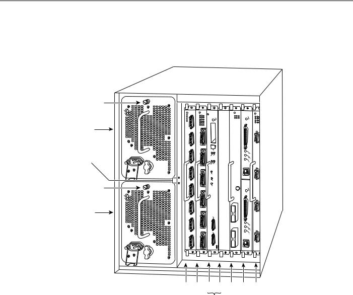
In the Cisco 7507 (see Figure 6), slots 0 and 1 and 4 through 6 are for interface processors including the FEIP.
Figure 6 Cisco 7507 (Interface Processor End)
Captive |
|
|
|
|
|
|
|
installation screw |
|
|
|
|
|
|
|
|
DC |
|
|
|
|
|
|
|
FAIL |
|
|
|
|
|
|
|
AC |
|
|
|
|
|
|
|
POWER |
|
|
|
|
ENABLE |
|
|
|
|
NORMAL |
|
|
|
|
|
|
|
|
|
|
|
|
Upper |
|
|
|
|
|
|
|
power supply |
|
|
|
|
|
|
|
Chassis |
|
|
EJECT |
|
|
|
|
grounding |
I |
|
SLOT0 |
1 |
|
|
|
|
|
SLOT |
|
|
|
|
|
receptacles |
|
|
SLAVEMASTER |
|
|
|
|
|
O |
|
|
|
|
||
Captive |
|
|
SLAVE/MASTER |
|
|
|
|
|
|
CPU |
HALT |
|
ENABLE |
|
|
installation screw |
|
|
|
|
|
||
|
|
RESET |
|
|
|||
|
|
|
|
|
|||
|
DC |
|
|
|
|
|
|
|
FAIL |
|
|
|
|
|
|
|
AC |
|
|
|
|
|
|
|
POWER |
|
|
|
|
|
H3888 |
Lower |
|
|
|
|
|
|
|
|
|
|
|
|
|
|
|
power supply |
|
|
AUX. |
|
|
|
|
|
|
|
|
|
|
|
|
|
|
|
CONSOLE |
ROUTE |
|
|
|
|
|
|
PROCESSORSWITCH |
|
|
|
|
|
I |
|
|
|
|
|
|
|
|
|
|
2 |
|
|
|
|
O |
|
|
|
|
|
|
|
Slot 0 |
1 |
2 |
3 |
4 |
5 |
6 |
|
|
|
RSP slots |
|
|
|
|
Fast Ethernet Interface Processor (FEIP) Installation and Configuration 13
Loading...