


 Loading...
Catalyst 6500 Series Supervisor Engine Flash PC
Card Installation Note
Product Numbers:
MEM-C6K-FLC16M(=)
MEM-C6K-FLC24M(=)
MEM-C6K-FLC64M(=)
MEM-C6K-ATA-1-64M(=)
This installation note contains the procedure to install a Flash PC card in the Catalyst 6500 series supervisor engines.
Note The 64-MB ATA Flash PC card (MEM-C6K-ATA-1-64M) requires Supervisor Engine 2 with ROMMON software release 7.1(1) or later releases. For ROMMON software upgrade details, refer to http://www.cisco.com/univercd/cc/td/doc/product/lan/cat6000/relnotes/78_13488.htm.
The ATA Flash PC card is supported on Catalyst 6500 series switches running Cisco IOS Release 12.1(8a)EX or later releases on both the supervisor engine and the Multilayer Switch Feature Card (MSFC).
The ATA Flash PC card is supported on Catalyst 6500 series switches running Catalyst software release 7.5(1) or later releases on the supervisor engine and Cisco IOS on the MSFC.
Note The 64-MB linear Flash PC card (MEM-C6K-FLC64M) is supported only on Supervisor Engine 1 and requires ROMMON software release 5.3(1) or later releases.
The 64-MB linear Flash PC card is supported on Catalyst 6500 series switches running Cisco IOS Release 12.1(13)E4 or later releases on both the supervisor engine and the MSFC.
The 64-MB linear Flash PC card is supported on Catalyst 6500 series switches running Catalyst software release 7.5(1) or later releases on the supervisor engine and Cisco IOS software on the MSFC.
Corporate Headquarters:
Cisco Systems, Inc., 170 West Tasman Drive, San Jose, CA 95134-1706 USA
© 1999–2005 Cisco Systems, Inc. All rights reserved.

Contents
Contents
This installation note contains the following sections:
•Supervisor Engine Flash PC Cards, page 2
•Preventing Electrostatic Discharge Damage, page 3
•Installing and Removing a Flash PC Card, page 3
•Using Flash PC Cards, page 6
•Additional Documentation, page 8
•Obtaining Documentation, page 8
•Documentation Feedback, page 9
•Cisco Product Security Overview, page 9
•Obtaining Technical Assistance, page 10
•Obtaining Additional Publications and Information, page 12
Supervisor Engine Flash PC Cards
The supervisor engine Flash PC cards conform with the PCMCIA format. These models are available:
•16-MB MEM-C6K-FLC16M
•24-MB MEM-C6K-FLC24M
•64-MB MEM-C6K-FLC64M
•MEM-C6K-ATA-1-64M
Note The 16-MB MEM-C6K-FLC16M and 24-MB MEM-C6K-FLC24M linear Flash PC cards are formatted for the Catalyst 6500 series supervisor engines and are ready to use.
The MEM-C6K-ATA-1-64M and 64-MB MEM-C6K-FLC64M Flash PC cards are not formatted. You must format these cards (See Table 1 on page 7 Commands for Using and Managing Flash DevicesTable 1for a description of the format command.) When you enter the dir disk0: or dir slot0: commands, an unformatted Flash PC card returns a “bad device block info” or “invalid magic number” error message.
Note Supervisor Engine 1 and Supervisor Engine 2 do not support the same Flash PC card format. To use a Flash PC card with Supervisor Engine 2, you must format the card with Supervisor Engine 2. To use a Flash PC card with Supervisor Engine 1, you must format the card with Supervisor Engine 1.
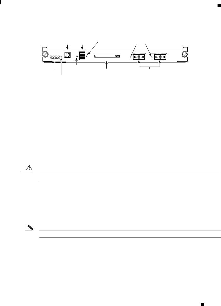
You can use Flash PC cards to store and boot software images, or they can be used as servers to store software images for other systems. You can configure each supervisor engine with one Flash PC card in slot 0. Figure 1 shows the front panel of a supervisor engine with the single PCMCIA slot, slot 0.
Catalyst 6500 Series Supervisor Engine Flash PC Card Installation Note
2 |
78-6507-06 |
|
|
Preventing Electrostatic Discharge Damage
Figure 1 |
Supervisor Engine Flash PC Card Slot |
Switch load |
|
CONSOLE port display |
PCMCIA LED |
WS-X6K-SUP1 |
|
|
|
|
Switch Load |
|
|
MGMT |
CONSOLE 100% |
|
|
PORT |
|
|
|
STATUS SYSTEMACTIVE PWR RESET |
MODE |
|
|
CONSOLE |
1% |
PCMCIA |
EJECT |
SUPERVISOR I |
|
|
|
|
|
|
|
CONSOLE PORT MODE |
|
||
Status LEDs |
switch |
PCMCIA slot |
|
RESET button |
|
|
|
LINK LEDs
PORT 1 |
PORT 2 |
LINK |
LINK |
1000BASE-X GBIC Uplink Ports
16057
For information about using the PCMCIA Flash PC cards, see the “Using Flash PC Cards” section on page 6.
Preventing Electrostatic Discharge Damage
Follow these guidelines to prevent electrostatic discharge (ESD) damage:
•Always use an ESD wrist or ankle strap, and ensure that it makes good skin contact.
•Connect the equipment end of the strap to the ESD connector on the switch.
•Place a removed Flash PC card on an antistatic surface or in a static shielding bag. If the card will be returned to the factory, immediately place it in a static shielding bag.
•Avoid contact between the card and clothing. The wrist strap only protects the card from ESD voltages on the body; ESD voltages on clothing can still cause damage.
Caution For safety, periodically check the resistance value of the antistatic strap. The measurement should be between 1 and 10 megohms.
Installing and Removing a Flash PC Card
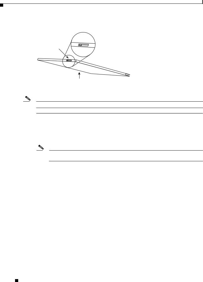
Before you install a Flash PC card, verify that the card’s write-protect switch is off. When the card is oriented with the printing side up and the edge connector end away from you, the write-protect switch is located on the front edge of the card, as shown in Figure 2.
Note Not all Flash PC cards have the write-protect switch.
Catalyst 6500 Series Supervisor Engine Flash PC Card Installation Note
|
78-6507-06 |
3 |
|
|
|
Installing and Removing a Flash PC Card
Figure 2 |
Locating the Flash PC Card Write Protection Switch |
|
Flash PC card |
Flash PC card |
shown with write |
write protection |
protection off |
 H2352
H2352
Flash PC card
To install and remove a Flash PC card (see Figure 3), perform these steps:
Note You can insert and remove the Flash PC card with the power on.
Step 1 Connect an ESD-preventive strap to the ESD connector on the switch.
Step 2 Face the front panel of the switch, and hold the Flash PC card with the connector end toward the slot, as shown in Figure 3a.
Step 3 Insert the card into the slot until it completely seats in the connector at the back of the slot and the eject button pops out toward you, as shown in Figure 3b.
Note The card does not insert all the way inside the slot; a portion of the card remains outside the slot.
Do not attempt to force the card past this point.
Step 4 To eject a Flash PC card, press the ejector button until the card is free of the connector at the back of the slot, as shown in Figure 3c.
Step 5 Remove the card from the slot and place it in an antistatic bag.
Catalyst 6500 Series Supervisor Engine Flash PC Card Installation Note
4 |
78-6507-06 |
|
|

Installing and Removing a Flash PC Card
Figure 3 |
Installing and Removing a Flash PC Card |
WS-X5530 |
|
SYSTEM |
FAN |
STATUS |
PS2 |
SUPERVISOR ENGINE |
PS1 |
I I I |
ACTIVE
RESET
|
100% |
|
|
|
SLOT |
1 |
|
|
0 |
|
|
CONSOLE AUX |
SLOT |
|
|
|
|
|
|
Switch Load |
|
PCMCIA |
EJECT |
|
|
|
a
WS-X5530 |
|
SYSTEM |
FAN |
STATUS |
PS2 |
SUPERVISOR ENGINE |
PS1 |
I I I |
ACTIVE
RESET
|
100% |
|
|
|
SLOT |
1 |
|
|
0 |
|
|
|
SLOT |
|
|
CONSOLE AUX |
|
|
|
|
|
|
|
Switch Load |
|
PCMCIA |
EJECT |
|
|
|
b
WS-X5530 |
|
SYSTEM |
FAN |
STATUS |
PS2 |
SUPERVISOR ENGINE |
PS1 |
I I I |
ACTIVE
RESET
|
100% |
|
|
|
SLOT |
1 |
|
|
0 |
|
|
|
SLOT |
|
|
CONSOLE AUX |
|
|
|
Switch Load |
|
PCMCIA |
EJECT |
|
|
|
c
14233
Catalyst 6500 Series Supervisor Engine Flash PC Card Installation Note
|
78-6507-06 |
5 |
|
|
|
Loading...