


3560-E
Table of contents
 Loading...
Corporate Headquarters:
© 2006 Cisco Systems, Inc. All rights reserved.
Cisco Systems, Inc., 170 West Tasman Drive, San Jose, CA 95134-1706 USA
Installation Notes for Catalyst 3750-E,
Catalyst 3560-E Switches and RPS 2300
Power Supply Modules
This document provides the removal and installation procedures for the power supply modules used with
the Catalyst 3750-E, the Catalyst 3560-E switches, and the Cisco Redundant Power System 2300
(RPS 2300).
For more information about using the power supply modules with a switch or an RPS 2300, see the
Catalyst 3750-E and Catalyst 3560-E Switch Hardware Installation Guide and the Cisco RPS 2300
Hardware Installation Guide on Cisco.com.
For translations of the safety warnings that appear in this publication, see the Regulatory Compliance
and Safety Information for the Catalyst 3750-E and Catalyst 3560-E Switch or the Cisco RPS 2300
Hardware Installation Guide that shipped with the product and that are also available on Cisco.com.
Contents
This document includes these sections:
• Product Overview, page 2
• Power Supply Module Installation, page 5
• Technical Specifications, page 12
• Related Publications, page 14
• Obtaining Documentation, page 14
• Documentation Feedback, page 15
• Cisco Product Security Overview, page 16
• Obtaining Technical Assistance, page 17
• Obtaining Additional Publications and Information, page 18

2
Installation Notes for Catalyst 3750-E, Catalyst 3560-E Switches and RPS 2300 Power Supply Modules
78-17570-01
Product Overview
Product Overview
Table 1 describes the power supply modules.
Table 2 describes the supported power supply modules for the switches and the RPS 2300.
For more information about which RPS 2300 power supply modules to use for specific switch support,
see the Cisco Redundant Power System 2300 Hardware Installation Guide.
The 750-W and 265-W AC power supply modules are autoranging units that support input voltages
between 100 and 240 VAC. The 1150-W power supply module is an autoranging unit that supports input
voltages between 115 and 240 VAC. The DC power supply module has dual input feeds (A and B) and
supports input voltages between 36 and 72 VDC.
The AC power supply modules include a power cord for connection to an AC power outlet. The 1150-W
and 750-W modules use a 16-AWG cord (only North America). All other modules use an 18-AWG cord.
The DC power supply module requires wiring to a DC-power source.
Table 1 Power Supply Module Part Numbers and Description
Part number Description
C3K-PWR-1150WAC 1150-W AC power supply module
C3K-PWR-750WAC 750-W AC power supply module
C3K-PWR-265WAC 265-W AC power supply module
C3K-PWR-265WDC 265-W DC power supply module
Table 2 Power Supply Modules Used with Switches and RPS 2300
Catalyst 3750-E and
Catalyst 3560-E
Switches and RPS 2300
1150 W AC
Power Supply
750 W AC
Power Supply
265 W AC
Power Supply
265 W DC
Power Supply
48-port PoE switch
1
1. For full 15.4-W support on a 48-port PoE switch, you must use the 1150-W AC power supply module in the switch.
Primary or spare Spare or primary Not allowed Not allowed
24-port PoE switch Spare or primary Primary or spare Not allowed Not allowed
48-port non-PoE
switch
Spare Spare Primary or spare Primary or spare
24-port non-PoE
switch
Spare Spare Primary or spare Primary or spare
RPS 2300
2
2. If only one power supply module is installed in the RPS 2300, you must install the blank insert in the empty power supply
slot.
Primary Primary Not allowed Not allowed
3
Installation Notes for Catalyst 3750-E, Catalyst 3560-E Switches and RPS 2300 Power Supply Modules
78-17570-01
Product Overview
Figure 1 to Figure 3 show the power supply modules.
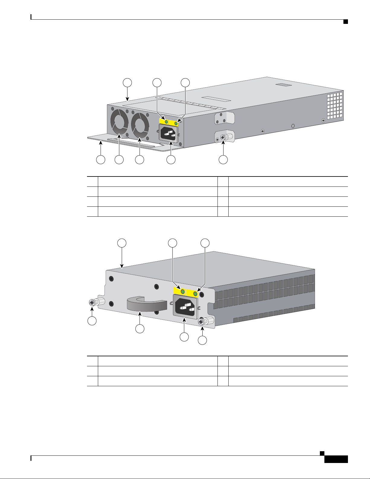
Figure 1 1150-W AC Power Supply Module
Figure 2 750-W AC and 265-W AC Power Supply Modules
1 1150-W AC power supply module 5 AC power connector
2 AC OK LED 6 Cooling fans
3 PS OK LED 7 Extraction handle
4 Captive screw
200058
AC OK PS OK
1
45667
32
1 750- or 265-W AC power supply module 4 Captive screws
2 AC OK LED 5 AC power connector
3 PS OK LED 6 Extraction handle
200057
AC OK PS OK
100-240 V
10-5 A
50-60 HZ
1
4
4
5
6
32
4
Installation Notes for Catalyst 3750-E, Catalyst 3560-E Switches and RPS 2300 Power Supply Modules
78-17570-01
Product Overview
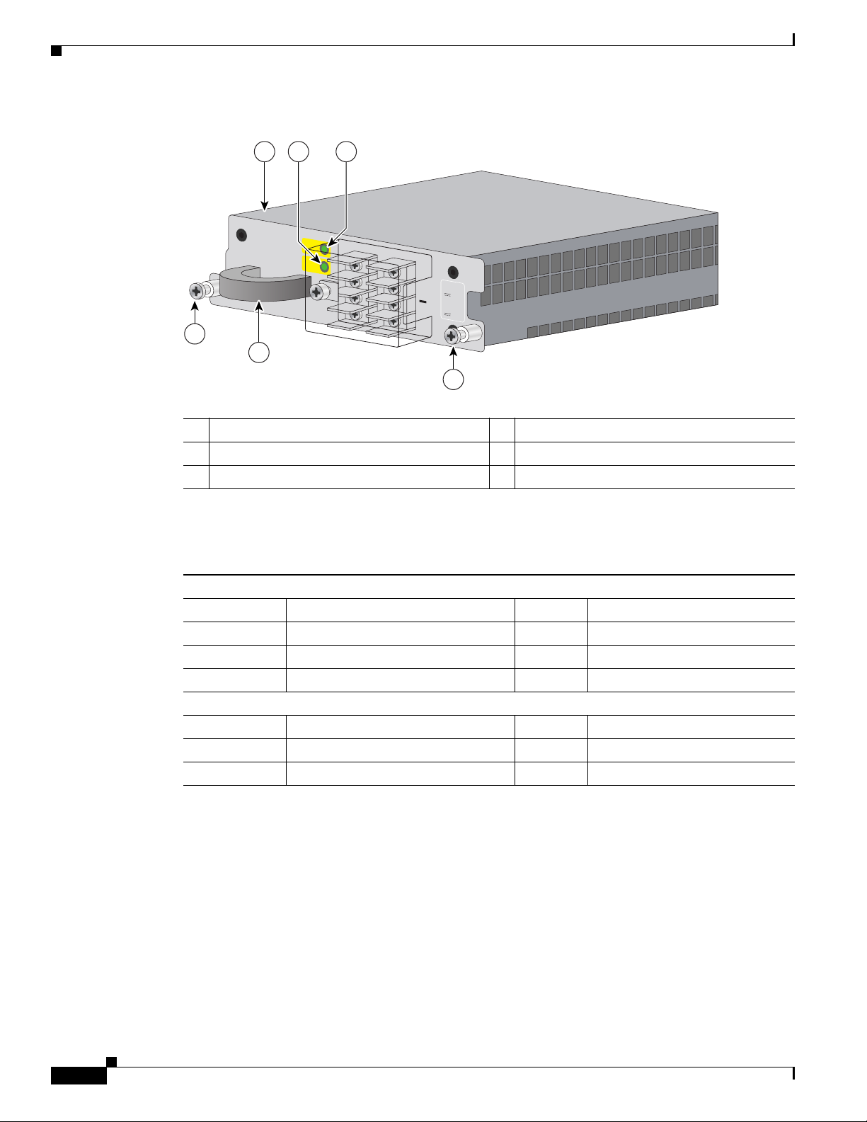
Figure 3 265-W DC Power Supply Module
The power supply modules have two status LEDs. Tab le 3 lists the LED colors and their meanings.
1 265-W DC power supply module 4 Captive screws
2 Input power terminals 5 Extraction handle
3 DC OK and PS OK LEDs
FRU CC 265W
DC IN
PS OK
A
+
A
+
IN
PU
T
-36 to -72V
/12A
O
U
TPU
T
265W
M
A
X
/22A
200059
1
4
4
5
32
Table 3 Power Supply Module LEDs
AC-Power Supply Module LEDs
AC OK Description PS OK Description
Off No AC input power Off Power supply failure
Green AC input power present Green Power output to switch active
Red No output power to switch
DC-Power Supply Module LEDs
DC IN Description PS OK Description
Off No DC input power Off Power supply failure
Green DC input power present Green Power output to switch active

5
Installation Notes for Catalyst 3750-E, Catalyst 3560-E Switches and RPS 2300 Power Supply Modules
78-17570-01
Power Supply Module Installation
Power Supply Module Installation
This section describes how to remove and install a new or replacement power supply module in
Catalyst 3750-E and Catalyst 3560-E switches, or an RPS 2300. See these sections:
• Tools and Equipment, page 5
• Installation Guidelines, page 5
• Installing an AC-Power Supply, page 6
• Installing a DC-Power Supply (Only Catalyst 3750-E and 3560-E Switches), page 8
Tools and Equipment
Obtain these necessary tools and equipment:
• Ratcheting torque screwdriver with a number-2 Phillips head that exerts up to 15 pound-force inches
(lbf-in.) or 240 ounce-force inches (ozf-in.) of pressure. For 1150-W power supply modules, the
screwdriver shaft length should be at least 6-inches long.
• Power-supply power-cord retainer in the switch accessory kit.
Installation Guidelines
Observe these guidelines when removing or installing a power supply module:
• Do not force the power supply module into the slot. This can damage the pins on the switch or the
RPS 2300 if they are not aligned with the unit.
• A power supply module that is only partially connected to the switch or the RPS 2300 can disrupt
the system operation.
• Remove power from the power supply module before removing or installing the module.
• The switch supports hot swapping of the power supply when the switch is connected to an RPS 2300
that can provide backup power. You can remove and replace the power supply without interrupting
normal switch operation. When you insert a new power supply in the switch, there is a 5-second
delay while the switch software polls the device. The switch power supply then automatically
provides power, and the RPS is available to power other devices.
• The RPS 2300 supports hot swapping of the power supply module when an external device is
connected to it.
–
If the RPS 2300 is not backing up an external device, you can remove and replace the power
supply module without disconnecting the system power.
–
If two 1150-W power supply modules are installed in the RPS 2300, you can remove one of the
modules when backing up an external device.
–
The RPS 2300 does not support hot swapping of the power supply module when two 750-W
power supply modules are installed and the RPS 2300 is backing up a device with an 1150-W
power supply.
• Make sure that you tighten the power supply module captive screws before moving the switch or the
RPS 2300.
• When replacing the 1150-W or the 750-W power supply module, verify that you are using the
correct power cord (CAB-16AWG-AC, only North America).
6
Installation Notes for Catalyst 3750-E, Catalyst 3560-E Switches and RPS 2300 Power Supply Modules
78-17570-01
Power Supply Module Installation
Warning
Do not reach into a vacant slot or chassis while you install or remove a module or a fan. Exposed
circuitry could constitute an energy hazard.
Statement 206
Warning
Only trained and qualified personnel should be allowed to install, replace, or service this equipment.
Statement 1030
Warning
Do not work on the system or connect or disconnect cables during periods of lightning activity.
Statement 1001
Installing an AC-Power Supply
To remove and install an AC-powered power supply module, follow these steps:
Step 1 Turn off the power at its source.
Step 2 Detach the power cord retainer from the power cord.
Step 3 Remove the power cord from the power connector.
Step 4 Use a Phillips screwdriver to loosen the two captive screws at the lower edge that secure the power
supply to the chassis.
Caution Do not leave the power supply slot open for more than 90 seconds while the switch or the RPS 2300 is
operational.
Step 5 Remove the power supply module from the power slot by pulling on the extraction handle.
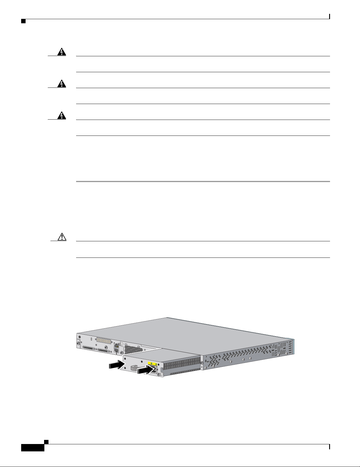
Step 6 Insert the new power supply into the power supply slot, and gently push it into the slot (Figure 4 and
Figure 5). When correctly inserted, the power supply is flush with the panel. Note: the 1150-W power
supply module extends 3.6 inches (9.14 cm) from the panel.
Figure 4 Inserting an AC-Power Supply into a Switch
158122
AC OK PS OK
100-240 V
10-5 A
50-60 HZ
Loading...