


 Loading...
Catalyst 2900 Series XL
Hardware Installation Guide
April 2001
Corporate Headquarters
Cisco Systems, Inc. 170 West Tasman Drive
San Jose, CA 95134-1706 USA http://www.cisco.com Tel: 408 526-4000
800 553-NETS (6387) Fax: 408 526-4100
Customer Order Number: DOC-786461=
Text Part Number: 78-6461-03
THE SPECIFICATIONS AND INFORMATION REGARDING THE PRODUCTS IN THIS MANUAL ARE SUBJECT TO CHANGE WITHOUT NOTICE. ALL STATEMENTS, INFORMATION, AND RECOMMENDATIONS IN THIS MANUAL ARE BELIEVED TO BE ACCURATE BUT ARE PRESENTED WITHOUT WARRANTY OF ANY KIND, EXPRESS OR IMPLIED. USERS MUST TAKE FULL RESPONSIBILITY FOR THEIR APPLICATION OF ANY PRODUCTS.
THE SOFTWARE LICENSE AND LIMITED WARRANTY FOR THE ACCOMPANYING PRODUCT ARE SET FORTH IN THE INFORMATION PACKET THAT SHIPPED WITH THE PRODUCT AND ARE INCORPORATED HEREIN BY THIS REFERENCE. IF YOU ARE UNABLE TO LOCATE THE SOFTWARE LICENSE OR LIMITED WARRANTY, CONTACT YOUR CISCO REPRESENTATIVE FOR A COPY.
The following information is for FCC compliance of Class A devices: This equipment has been tested and found to comply with the limits for a Class A digital device, pursuant to part 15 of the FCC rules. These limits are designed to provide reasonable protection against harmful interference when the equipment is operated in a commercial environment. This equipment generates, uses, and can radiate radio-frequency energy and, if not installed and used in accordance with the instruction manual, may cause harmful interference to radio communications. Operation of this equipment in a residential area is likely to cause harmful interference, in which case users will be required to correct the interference at their own expense.
The following information is for FCC compliance of Class B devices: The equipment described in this manual generates and may radiate radio-frequency energy. If it is not installed in accordance with Cisco’s installation instructions, it may cause interference with radio and television reception. This equipment has been tested and found to comply with the limits for a Class B digital device in accordance with the specifications in part 15 of the FCC rules. These specifications are designed to provide reasonable protection against such interference in a residential installation. However, there is no guarantee that interference will not occur in a particular installation.
Modifying the equipment without Cisco’s written authorization may result in the equipment no longer complying with FCC requirements for Class A or Class B digital devices. In that event, your right to use the equipment may be limited by FCC regulations, and you may be required to correct any interference to radio or television communications at your own expense.
You can determine whether your equipment is causing interference by turning it off. If the interference stops, it was probably caused by the Cisco equipment or one of its peripheral devices. If the equipment causes interference to radio or television reception, try to correct the interference by using one or more of the following measures:
•Turn the television or radio antenna until the interference stops.
•Move the equipment to one side or the other of the television or radio.
•Move the equipment farther away from the television or radio.
•Plug the equipment into an outlet that is on a different circuit from the television or radio. (That is, make certain the equipment and the television or radio are on circuits controlled by different circuit breakers or fuses.)
Modifications to this product not authorized by Cisco Systems, Inc. could void the FCC approval and negate your authority to operate the product.
The Cisco implementation of TCP header compression is an adaptation of a program developed by the University of California, Berkeley (UCB) as part of UCB’s public domain version of the UNIX operating system. All rights reserved. Copyright © 1981, Regents of the University of California.
NOTWITHSTANDING ANY OTHER WARRANTY HEREIN, ALL DOCUMENT FILES AND SOFTWARE OF THESE SUPPLIERS ARE PROVIDED “AS IS” WITH ALL FAULTS. CISCO AND THE ABOVE-NAMED SUPPLIERS DISCLAIM ALL WARRANTIES, EXPRESSED OR IMPLIED, INCLUDING, WITHOUT LIMITATION, THOSE OF MERCHANTABILITY, FITNESS FOR A PARTICULAR PURPOSE AND NONINFRINGEMENT OR ARISING FROM A COURSE OF DEALING, USAGE, OR TRADE PRACTICE.
IN NO EVENT SHALL CISCO OR ITS SUPPLIERS BE LIABLE FOR ANY INDIRECT, SPECIAL, CONSEQUENTIAL, OR INCIDENTAL DAMAGES, INCLUDING, WITHOUT LIMITATION, LOST PROFITS OR LOSS OR DAMAGE TO DATA ARISING OUT OF THE USE OR INABILITY TO USE THIS MANUAL, EVEN IF CISCO OR ITS SUPPLIERS HAVE BEEN ADVISED OF THE POSSIBILITY OF SUCH DAMAGES.
AccessPath, AtmDirector, Browse with Me, CCDA, CCDE, CCDP, CCIE, CCNA, CCNP, CCSI, CD-PAC, CiscoLink, the Cisco NetWorks logo, the Cisco Powered Network logo, Cisco Systems Networking Academy, the Cisco Systems Networking Academy logo, Fast Step, Follow Me Browsing, FormShare, FrameShare, GigaStack, IGX, Internet Quotient, IP/VC, iQ Breakthrough, iQ Expertise, iQ FastTrack, the iQ Logo, iQ Net Readiness Scorecard, MGX, the Networkers logo, Packet, PIX, RateMUX, ScriptBuilder, ScriptShare, SlideCast, SMARTnet, TransPath, Unity, Voice LAN, Wavelength Router, and WebViewer are trademarks of Cisco Systems, Inc.; Changing the Way We Work, Live, Play, and Learn, Discover All That’s Possible, and Empowering the Internet Generation, are service marks of Cisco Systems, Inc.; and Aironet, ASIST, BPX, Catalyst, Cisco, the Cisco Certified Internetwork Expert logo, Cisco IOS, the Cisco IOS logo, Cisco Systems, Cisco Systems Capital, the Cisco Systems logo,
Enterprise/Solver, EtherChannel, EtherSwitch, FastHub, FastSwitch, IOS, IP/TV, LightStream, MICA, Network Registrar, Post-Routing, Pre-Routing, Registrar, StrataView Plus, Stratm, SwitchProbe, TeleRouter, and VCO are registered trademarks of Cisco Systems, Inc. or its affiliates in the U.S. and certain other countries.
All other brands, names, or trademarks mentioned in this document or Web site are the property of their respective owners. The use of the word partner does not imply a partnership relationship between Cisco and any other company. (0102R)
Catalyst 2900 Series XL Hardware Installation Guide
Copyright © 2001, Cisco Systems, Inc.
All rights reserved.

|
|
|
|
|
|
|
C O N T E N T S |
||
|
|
Preface xi |
|
|
|
|
|
|
|
|
|
Audience |
xi |
|
|
|
|
|
|
|
|
Purpose |
xi |
|
|
|
|
|
|
|
|
Organization |
xii |
|
|
|
|
|
|
|
|
Conventions |
xii |
|
|
|
|
|
|
|
|
Related Publications xvi |
|
|
|
|
|||
|
|
Obtaining Documentation xvii |
|
|
|
|
|||
|
|
World Wide Web xvii |
|
|
|
|
|||
|
|
Cisco Documentation CD-ROM |
xvii |
||||||
|
|
Ordering Documentation xviii |
|
|
|
||||
|
|
Documentation Feedback |
xviii |
|
|
|
|||
|
|
Obtaining Technical Assistance |
xix |
|
|
|
|||
|
|
Cisco.com xix |
|
|
|
|
|||
|
|
Technical Assistance Center xix |
|||||||
|
|
Contacting TAC by Using the Cisco TAC Website xx |
|||||||
|
|
Contacting TAC by Telephone xx |
|||||||
|
Product Overview 1-1 |
|
|
|
|
||||
C H A P T E R 1 |
|
|
|
|
|||||
|
|
Features |
1-1 |
|
|
|
|
|
|
|
|
Management Interface Options |
1-4 |
|
|
||||
|
|
Front-Panel Description 1-5 |
|
|
|
|
|||
|
|
10/100 Ports |
1-6 |
|
|
|
|
||
|
|
100BASE-FX Ports |
1-7 |
|
|
|
|
||
|
|
Long-Reach Ethernet Ports |
1-7 |
|
|
|
|||
|
|
|
|
|
Catalyst 2900 Series XL Hardware Installation Guide |
|
|
||
|
|
|
|
|
|
||||
|
78-6461-03 |
|
|
|
|
|
|
|
v |
|
|
|
|
|
|
|
|
||

Contents
|
|
|
|
Expansion Slots |
1-8 |
|
|
|
|
|
||||
|
|
|
|
LEDs |
1-9 |
|
|
|
|
|
|
|
|
|
|
|
|
|
System LED |
1-11 |
|
|
|
|
|||||
|
|
|
|
RPS LED |
1-12 |
|
|
|
|
|
|
|||
|
|
|
|
Port LEDs and Modes |
1-13 |
|
|
|||||||
|
|
|
|
Expansion Slot LEDs |
1-17 |
|
|
|||||||
|
|
|
|
Rear-Panel Description |
1-18 |
|
|
|
|
|||||
|
|
|
|
Power Connectors |
1-19 |
|
|
|
|
|||||
|
|
|
|
Internal Power Supply Connector 1-19 |
||||||||||
|
|
|
|
Cisco RPS Connector |
1-19 |
|
|
|||||||
|
|
|
|
Console Port |
1-21 |
|
|
|
|
|
|
|||
|
|
Installation |
2-1 |
|
|
|
|
|
|
|
|
|
||
C H A P T E R 2 |
|
|
|
|
|
|
|
|
|
|
||||
|
|
|
|
Preparing for Installation |
2-1 |
|
|
|
|
|||||
|
|
|
|
Warnings |
2-1 |
|
|
|
|
|
|
|
||
|
|
|
|
EMC Regulatory Statements |
2-4 |
|
|
|||||||
|
|
|
|
U.S.A. |
2-4 |
|
|
|
|
|
|
|
||
|
|
|
|
Taiwan |
2-4 |
|
|
|
|
|
|
|
||
|
|
|
|
Hungary |
2-5 |
|
|
|
|
|
|
|||
|
|
|
|
Installation Guidelines 2-5 |
|
|
|
|||||||
|
|
|
|
Verifying Package Contents |
2-6 |
|
|
|||||||
|
|
|
|
Installing the Switch on a Table or Shelf |
2-7 |
|
||||||||
|
|
|
|
Installing the Switch in a Rack |
2-8 |
|
|
|||||||
|
|
|
|
Removing Screws from the Switch |
2-10 |
|
||||||||
|
|
|
|
Attaching the Brackets to a Catalyst 2912 XL, 2924C XL, 2924 XL, 2912MF XL, |
||||||||||
|
|
|
|
or 2924M XL Switch |
2-11 |
|
|
|
||||||
|
|
|
|
Attaching the Brackets to a Catalyst 2912 LRE XL or 2924 LRE XL |
||||||||||
|
|
|
|
Switch 2-17 |
|
|
|
|
|
|
|
|
||
|
|
|
|
Mounting the Switch in a Rack 2-19 |
||||||||||
|
|
|
|
Attaching the Optional Cable Guide |
2-20 |
|
||||||||
|
|
|
Catalyst 2900 Series XL Hardware Installation Guide |
|
|
|
|
|||||||
|
|
|
|
|
|
|
||||||||
vi |
|
|
|
|
|
|
|
|
|
|
|
|
78-6461-03 |
|
|
|
|
|
|
|
|
|
|
|
|
|
|
||

Contents
Installing the Switch on a Wall |
2-22 |
|
Attaching the Brackets to the Switch 2-22 |
||
Mounting the Switch to a Wall 2-23 |
||
Powering On the Switch and Running POST 2-25 |
||
Connecting to a 10/100 Port |
2-26 |
|
Connecting to a 100BASE-FX Port 2-28 |
||
Connecting to an LRE Port 2-30 |
|
|
Connecting to a Module Port |
2-33 |
|
Connecting to the Console Port |
2-33 |
|
Where to Go Next 2-34 |
|
|
C H A P T E R 3 |
Troubleshooting 3-1 |
|
|
|
|
|
|
Understanding POST Results 3-2 |
|
|
|
|
|
Correcting Module POST Failures |
3-3 |
|
|
|
|
Diagnosing Problems 3-3 |
|
|
|
|
Technical Specifications A-1 |
|
|
|
|
A P P E N D I X A |
|
|
|
||
|
Connectors and Cable Specifications |
B-1 |
|||
A P P E N D I X B |
|||||
|
|
Connector Specifications B-1 |
|
|
|
|
|
10/100 Ports B-1 |
|
|
|
|
|
100BASE-FX Ports B-2 |
|
|
|
|
|
LRE Ports B-3 |
|
|
|
|
|
Console Port B-3 |
|
|
|
|
|
Cable and Adapter Specifications B-4 |
|||
|
|
Crossover and Straight-Through Cable Pinouts B-4 |
|||
|
|
RJ-21 Cable Pinouts B-5 |
|
|
|
|
|
Console Port B-5 |
|
|
|
|
|
Catalyst 2900 Series XL Hardware Installation Guide |
|
|
|
|
|
|
|||
|
78-6461-03 |
|
|
|
vii |
|
|
|
|
||

Contents
Identifying a Rollover Cable B-6
Connecting to a PC B-6
Connecting to a Terminal B-7
A P P E N D I X C Translated Safety Warnings C-1
Attaching the Cisco RPS (model PWR600-AC-RPS) C-2
Attaching the Cisco RPS (model PWR300-AC-RPS-N1) C-3
Qualified Personnel Warning C-4
Installation Warning C-5
Jewelry Removal Warning C-6
Stacking the Chassis Warning C-8
Main Disconnecting Device C-9
Overtemperature Warning C-10
TN Power Warning C-13
Ground Connection Warning C-14
Circuit Breaker (15A) Warning C-15
Grounded Equipment Warning C-17
Supply Circuit Warning C-18
Voltage Warning C-19
Power Supply Warning C-21
Lightning Activity Warning C-23
Product Disposal Warning C-24
Class 1 Laser Product Warning C-25
Laser Beam Exposure Warning C-26
Catalyst 2900 Series XL Hardware Installation Guide
viii |
78-6461-03 |
|
|

Contents
No On/Off Switch Warning C-27
Chassis Warning—Rack-Mounting and Servicing C-29
I N D E X
Catalyst 2900 Series XL Hardware Installation Guide
|
78-6461-03 |
ix |
|

Contents
Catalyst 2900 Series XL Hardware Installation Guide
x |
78-6461-03 |
|
|
Preface
Audience
This guide is for the networking or computer technician responsible for installing and configuring a Catalyst 2900 series XL switch. We assume that you are familiar with the concepts and terminology of Ethernet and local area networking.
Purpose
The Catalyst 2900 Series XL Hardware Installation Guide documents the hardware features of Catalyst 2900 series XL switches. It describes the physical and performance characteristics of the switches, explains how to install a switch, and provides troubleshooting information and specifications.
Catalyst 2900 Series XL Hardware Installation Guide
|
78-6461-03 |
xi |
|

Preface
Organization
Organization
This guide is organized into the following chapters:
Chapter 1, “Product Overview,” summarizes the switch features, and describes the ports, the standards they support, and the LEDs.
Chapter 2, “Installation,” provides the procedures for installing a switch in a rack, on a desk, or on a wall.
Chapter 3, “Troubleshooting,” describes how to identify and resolve some of the problems that might arise when you are installing the switch.
Appendix A, “Technical Specifications,” lists the physical and environmental specifications for the switches and the regulatory agency approvals.
Appendix B, “Connectors and Cable Specifications,” describes the connectors, cables, and adapters that can be used to connect to the switch.
Appendix C, “Translated Safety Warnings,” provides translations in various languages of the warnings in this guide.
Conventions
This guide uses the following conventions to convey instructions and information:
Command descriptions use these conventions:
•Commands and keywords are in boldface.
•Arguments for which you supply values are in italic. Examples use these conventions:
•Terminal sessions and system displays are in screen font.
•Information you enter is in boldface screen font.
•Nonprinting characters, such as passwords or tabs, are in angle brackets (< >).
Catalyst 2900 Series XL Hardware Installation Guide
xii |
78-6461-03 |
|
|

Preface
Conventions
Notes, cautions, and warnings use the following conventions and symbols:
Note Means reader take note. Notes contain helpful suggestions or references to materials not contained in this manual.
Caution Means reader be careful. In this situation, you might do something that could result in equipment damage or loss of data.
Warning This warning symbol means danger. You are in a situation that could cause bodily injury. Before you work on any equipment, be aware of the hazards involved with electrical circuitry and be familiar with standard practices for preventing accidents. (To see translations of the warnings that appear in this publication, refer to the Appendix C, “Translated Safety Warnings.”)
Waarschuwing Dit waarschuwingssymbool betekent gevaar. U verkeert in een situatie die lichamelijk letsel kan veroorzaken. Voordat u aan enige apparatuur gaat werken, dient u zich bewust te zijn van de bij elektrische schakelingen betrokken risico’s en dient u op de hoogte te zijn van standaard maatregelen om ongelukken te voorkomen. (Voor vertalingen van de waarschuwingen die in deze publicatie verschijnen, kunt u het aanhangsel C “Translated Safety Warnings” (Vertalingen van veiligheidsvoorschriften) raadplegen.)
Varoitus Tämä varoitusmerkki merkitsee vaaraa. Olet tilanteessa, joka voi johtaa ruumiinvammaan. Ennen kuin työskentelet minkään laitteiston parissa, ota selvää sähkökytkentöihin liittyvistä vaaroista ja tavanomaisista onnettomuuksien ehkäisykeinoista. (Tässä julkaisussa esiintyvien varoitusten käännökset löydät liitteestä C "Translated Safety Warnings" (käännetyt turvallisuutta koskevat varoitukset).)
Catalyst 2900 Series XL Hardware Installation Guide
|
78-6461-03 |
xiii |
|

Preface
Conventions
Attention Ce symbole d’avertissement indique un danger. Vous vous trouvez dans une situation pouvant entraîner des blessures. Avant d’accéder à cet équipement, soyez conscient des dangers posés par les circuits électriques et familiarisez-vous avec les procédures courantes de prévention des accidents. Pour obtenir les traductions des mises en garde figurant dans cette publication, veuillez consulter l’annexe intitulée C « Translated Safety Warnings » (Traduction des avis de sécurité).
Warnung Dieses Warnsymbol bedeutet Gefahr. Sie befinden sich in einer Situation, die zu einer Körperverletzung führen könnte. Bevor Sie mit der Arbeit an irgendeinem Gerät beginnen, seien Sie sich der mit elektrischen Stromkreisen verbundenen Gefahren und der Standardpraktiken zur Vermeidung von Unfällen bewußt. (Übersetzungen der in dieser Veröffentlichung enthaltenen Warnhinweise finden Sie im Anhang mit dem Titel C “Translated Safety Warnings” (Übersetzung der Warnhinweise).)
Avvertenza Questo simbolo di avvertenza indica un pericolo. Si è in una situazione che può causare infortuni. Prima di lavorare su qualsiasi apparecchiatura, occorre conoscere i pericoli relativi ai circuiti elettrici ed essere al corrente delle pratiche standard per la prevenzione di incidenti. La traduzione delle avvertenze riportate in questa pubblicazione si trova nell’appendice C, “Translated Safety Warnings” (Traduzione delle avvertenze di sicurezza).
Advarsel Dette varselsymbolet betyr fare. Du befinner deg i en situasjon som kan føre til personskade. Før du utfører arbeid på utstyr, må du være oppmerksom på de faremomentene som elektriske kretser innebærer, samt gjøre deg kjent med vanlig praksis når det gjelder å unngå ulykker. (Hvis du vil se oversettelser av de advarslene som finnes i denne publikasjonen, kan du se i vedlegget C "Translated Safety Warnings" [Oversatte sikkerhetsadvarsler].)
Catalyst 2900 Series XL Hardware Installation Guide
xiv |
78-6461-03 |
|
|

Preface
Conventions
Aviso Este símbolo de aviso indica perigo. Encontra-se numa situação que lhe poderá causar danos fisicos. Antes de começar a trabalhar com qualquer equipamento, familiarize-se com os perigos relacionados com circuitos eléctricos, e com quaisquer práticas comuns que possam prevenir possíveis acidentes. (Para ver as traduções dos avisos que constam desta publicação, consulte o apêndice C “Translated Safety Warnings” - “Traduções dos Avisos de Segurança”).
¡Advertencia! Este símbolo de aviso significa peligro. Existe riesgo para su integridad física. Antes de manipular cualquier equipo, considerar los riesgos que entraña la corriente eléctrica y familiarizarse con los procedimientos estándar de prevención de accidentes. (Para ver traducciones de las advertencias que aparecen en esta publicación, consultar el apéndice titulado C “Translated Safety Warnings.”)
Varning! Denna varningssymbol signalerar fara. Du befinner dig i en situation som kan leda till personskada. Innan du utför arbete på någon utrustning måste du vara medveten om farorna med elkretsar och känna till vanligt förfarande för att förebygga skador. (Se förklaringar av de varningar som förekommer i denna publikation i appendix C "Translated Safety Warnings" [Översatta säkerhetsvarningar].)
Catalyst 2900 Series XL Hardware Installation Guide
|
78-6461-03 |
xv |
|

Preface
Related Publications
Related Publications
You can order printed copies of documents with a DOC-xxxxxx= number.
The following publications provide more information about the switches:
•Release Notes for the Catalyst 2900 Series XL and Catalyst 3500 Series XL, Cisco IOS Release 12.0(5)WC(1)
•Catalyst 2900 XL and Catalyst 3500 XL Documentation CD
Note This product-specific CD contains only the Catalyst 2900 XL and Catalyst 3500 XL switch documents and related hardware documents. This CD is not the same as the Cisco Documentation CD-ROM, which contains the documentation for all Cisco products and is shipped with all Cisco products.
This CD is shipped with the switch and has the following publications:
–This Catalyst 2900 Series XL Hardware Installation Guide
(order number DOC-786461=)
–Catalyst 2900 Series XL and Catalyst 3500 Series XL Software Configuration Guide, Cisco IOS Release 12.0(5)WC(1)
(order number DOC-786511=)
–Catalyst 2900 Series XL and Catalyst 3500 Series XL Command Reference, Cisco IOS Release 12.0(5)WC(1)
(order number DOC-7812155=)
–Catalyst 2900 Series XL Modules Installation Guide
(order number DOC-CAT2900-IG=)
–Catalyst 2900 Series XL ATM Modules Installation and Configuration Guide (order number DOC-785472=)
–1000BASE-T Gigabit Interface Converter Installation Note
(not orderable but is available on Cisco.com)
–Catalyst GigaStack Gigabit Interface Converter Hardware Installation Guide (order number DOC-786460=)
Catalyst 2900 Series XL Hardware Installation Guide
xvi |
78-6461-03 |
|
|

Preface
Obtaining Documentation
–Cisco 575 LRE CPE Hardware Installation Guide (order number DOC-7811469=)
•Installation Notes for the Cisco LRE 48 POTS Splitter (order number DOC-7812250=)
Obtaining Documentation
The following sections provide sources for obtaining documentation from Cisco Systems.
World Wide Web
You can access the most current Cisco documentation on the World Wide Web at the following sites:
•http://www.cisco.com
•http://www-china.cisco.com
•http://www-europe.cisco.com
Cisco Documentation CD-ROM
Cisco documentation and additional literature are available in a CD-ROM package, which ships with your product. The Cisco Documentation CD-ROM is updated monthly and may be more current than printed documentation. The CD-ROM package is available as a single unit or as an annual subscription.
Note This CD contains the documentation for all Cisco products and is shipped with all Cisco products. This CD is not the same as the Catalyst 2900 XL and Catalyst 3500 XL Documentation CD, which contains only the
Catalyst 2900 XL and Catalyst 3500 XL switch documents and related hardware documents.
|
|
Catalyst 2900 Series XL Hardware Installation Guide |
|
|
|
|
|
||
|
78-6461-03 |
|
|
xvii |
|
|
|

Preface
Obtaining Documentation
Ordering Documentation
Cisco documentation is available in the following ways:
•Registered Cisco Direct Customers can order Cisco Product documentation from the Networking Products MarketPlace:
http://www.cisco.com/cgi-bin/order/order_root.pl
•Registered Cisco.com users can order the Documentation CD-ROM through the online Subscription Store:
http://www.cisco.com/go/subscription
•Nonregistered CCO users can order documentation through a local account representative by calling Cisco corporate headquarters (California, USA) at 408 526-7208 or, in North America, by calling 800 553-NETS(6387).
Documentation Feedback
If you are reading Cisco product documentation on the World Wide Web, you can send us your comments by completing the online survey. When you display the document listing for this platform, click Give Us Your Feedback. If you are using the product-specific CD and you are connected to the Internet, click the pencil-and-paper icon in the toolbar to display the survey. After you display the survey, select the manual that you wish to comment on. Click Submit to send your comments to the Cisco documentation group.
You can e-mail your comments to bug-doc@cisco.com.
To submit your comments by mail, for your convenience many documents contain a response card behind the front cover. Otherwise, you can mail your comments to the following address:
Cisco Systems, Inc.
Document Resource Connection
170 West Tasman Drive
San Jose, CA 95134-9883
We appreciate your comments.
|
Catalyst 2900 Series XL Hardware Installation Guide |
xviii |
78-6461-03 |

Preface
Obtaining Technical Assistance
Obtaining Technical Assistance
Cisco provides Cisco.com as a starting point for all technical assistance. Customers and partners can obtain documentation, troubleshooting tips, and sample configurations from online tools. For Cisco.com registered users, additional troubleshooting tools are available from the TAC website.
Cisco.com
Cisco.com is the foundation of a suite of interactive, networked services that provides immediate, open access to Cisco information and resources at anytime, from anywhere in the world. This highly integrated Internet application is a powerful, easy-to-use tool for doing business with Cisco.
Cisco.com provides a broad range of features and services to help customers and partners streamline business processes and improve productivity. Through Cisco.com, you can find information about Cisco and our networking solutions, services, and programs. In addition, you can resolve technical issues with online technical support, download and test software packages, and order Cisco learning materials and merchandise. Valuable online skill assessment, training, and certification programs are also available.
Customers and partners can self-register on Cisco.com to obtain additional personalized information and services. Registered users can order products, check on the status of an order, access technical support, and view benefits specific to their relationships with Cisco.
To access Cisco.com, go to the following website:
http://www.cisco.com
Technical Assistance Center
The Cisco TAC website is available to all customers who need technical assistance with a Cisco product or technology that is under warranty or covered by a maintenance contract.
Catalyst 2900 Series XL Hardware Installation Guide
|
78-6461-03 |
xix |
|

Preface
Obtaining Technical Assistance
Contacting TAC by Using the Cisco TAC Website
If you have a priority level 3 (P3) or priority level 4 (P4) problem, contact TAC by going to the TAC website:
http://www.cisco.com/tac
P3 and P4 level problems are defined as follows:
•P3—Your network performance is degraded. Network functionality is noticeably impaired, but most business operations continue.
•P4—You need information or assistance on Cisco product capabilities, product installation, or basic product configuration.
In each of the above cases, use the Cisco TAC website to quickly find answers to your questions.
To register for Cisco.com, go to the following website:
http://www.cisco.com/register/
If you cannot resolve your technical issue by using the TAC online resources, Cisco.com registered users can open a case online by using the TAC Case Open tool at the following website:
http://www.cisco.com/tac/caseopen
Contacting TAC by Telephone
If you have a priority level 1 (P1) or priority level 2 (P2) problem, contact TAC by telephone and immediately open a case. To obtain a directory of toll-free numbers for your country, go to the following website:
http://www.cisco.com/warp/public/687/Directory/DirTAC.shtml
P1 and P2 level problems are defined as follows:
•P1—Your production network is down, causing a critical impact to business operations if service is not restored quickly. No workaround is available.
•P2—Your production network is severely degraded, affecting significant aspects of your business operations. No workaround is available.
Catalyst 2900 Series XL Hardware Installation Guide
xx |
78-6461-03 |
|
|
C H A P T E R 1
Product Overview
This chapter provides the following topics that describe the
Catalyst 2900 series XL switches, hereafter referred to as the switches.
•Switch features, including management options
•Descriptions of the front and rear panels
•Descriptions of the LEDs
Features
The switches are stackable 10/100 Ethernet switches to which you can connect workstations, Cisco IP Phones, and other network devices such as servers, routers, and other switches. The 2900 XL LRE switches employ Long-Reach Ethernet (LRE), a very-high-data-rate digital subscriber line (VDSL)-based technology that allows an Ethernet network to reach distances up to 4921 feet (1500 meters). The switches can be deployed as backbone switches, aggregating 10/100 and Gigabit Ethernet traffic from other network devices.
The Catalyst 2900 XL switches have these features:
•Autonegotiates speed and duplex operation on all 10/100 ports
•Operates in full-duplex mode on all 100BASE-FX ports
•Checks for errors on a received packet, determines the destination port, stores the packet in shared memory, and then forwards the packet to the destination port
|
|
Catalyst 2900 Series XL Hardware Installation Guide |
|
|
|
|
|
||
|
78-6461-03 |
|
|
1-1 |
|
|
|

Chapter 1 Product Overview
Features
•On the Catalyst 2924M XL and Catalyst 2912MF XL switches, two expansion slots for 10BASE-T/100BASE-TX, 100BASE-FX, Gigabit Ethernet, and asynchronous transfer mode (ATM) modules
•On the Catalyst 2912 LRE XL and 2924 LRE XL switches, up to 24 LRE ports through one RJ-21 connector
•Supports up to 2048 MAC addresses on the Catalyst 2924 XL, 2924C XL, and 2912 XL switches
•Supports up to 8192 MAC addresses on the Catalyst 2924M XL and 2912MF XL switches
Figure 1-1 shows the switch models.
|
Catalyst 2900 Series XL Hardware Installation Guide |
1-2 |
78-6461-03 |
Chapter 1 Product Overview
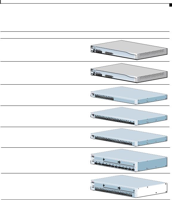
Figure 1-1 Catalyst 2900 Series XL Switches
Version Number |
|
Description |
WS-C2912-LRE-XL |
|
4 fixed autosensing 10/100 ports |
|
||
|
|
12 LRE ports |
WS-C2924-LRE-XL |
|
4 fixed autosensing 10/100 ports |
|
|
24 LRE ports |
WS-C2912-XL |
|
12 fixed autosensing 10/100 ports |
WS-C2924C-XL |
|
22 fixed autosensing 10/100 ports |
|
|
2 100BASE-FX ports |
WS-C2924-XL |
|
24 fixed autosensing 10/100 ports |
WS-C2912MF-XL |
|
12 100BASE-FX ports |
|
|
2 expansion slots |
WS-C2924M-XL |
|
24 fixed autosensing 10/100 ports |
|
|
2 expansion slots |
|
|
|
Features
Cisco RPS 300
Cisco RPS 300
Catalyst |
|
2900 |
XL |
Catalyst |
|
2900 |
XL |
Catalyst |
|
2900 |
XL |
Catalyst |
|
2900 |
XL |
Catalyst |
|
2900 |
XL |


 47294
47294
|
|
Catalyst 2900 Series XL Hardware Installation Guide |
|
|
|
|
|
||
|
78-6461-03 |
|
|
1-3 |
|
|
|

Chapter 1 Product Overview
Features
Management Interface Options
The Catalyst 2900 XL and Catalyst 3500 XL switches are designed for plug-and-play operation: you only need to assign basic IP information to the switch and connect it to the other devices in your network. If you have specific network needs, you can configure and monitor the switch—on an individual basis or as part of a switch cluster—through its various management interfaces.
You can configure and monitor individual switches and switch clusters by using the following interfaces:
•Cluster Management Suite (CMS)—CMS is a graphical user interface that can be launched from anywhere in your network through a web browser such as Netscape Communicator or Microsoft Internet Explorer. CMS is already installed on the switch, and no additional installation is required. Using CMS, you can fully configure and monitor a standalone switch, a specific cluster member, or an entire switch cluster. You can also display network topologies to gather link information, and display switch images to modify switchand port-level settings.
•Command-line Interface (CLI)—The switch CLI Cisco IOS software and is enhanced to support desktop-switching features. You can fully configure and monitor the switch and switch cluster members from the CLI. You can access the CLI either by connecting your management station directly to the switch console port or by using Telnet from a remote management station.
•Simple network management protocol (SNMP)—SNMP provides a means to monitor and control the switch and switch cluster members. You can manage switch configuration settings, performance, security, and collect statistics by using SNMP management applications such as CiscoWorks2000 LAN Management Suite (LMS) and HP OpenView.
You can manage the switch from an SNMP-compatible management station that is running platforms such as HP OpenView or SunNet Manager. The switch supports a comprehensive set of MIB extensions and four Remote Monitoring (RMON) groups.
For more information about CMS, the CLI, and SNMP refer to the Catalyst 2900 Series XL and Catalyst 3500 Series XL Software Configuration Guide.
|
Catalyst 2900 Series XL Hardware Installation Guide |
1-4 |
78-6461-03 |
Chapter 1 Product Overview
Front-Panel Description
Front-Panel Description
Depending on the model, the switch front panels can have up to 24 10/100 ports (See Figure 1-2), up to 12 100BASE-FX ports (See Figure 1-2), 2 expansion slots (see Figure 1-2), and up to 24 Long-Reach Ethernet ports (See Figure 1-4). All switches have a set of LEDs and a Mode button. This section describes these front-panel components.
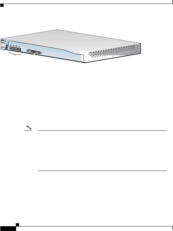
Figure 1-2 Catalyst 2900 XL Front-Panel 10/100 Ports
MODE 
Catalyst 2900
SERIES
 52646
52646
XL
100BASE-FX ports
Figure 1-3 Catalyst 2900 XL 100BASE-FX ports and Expansion Slots
Expansion slots
MODE
Catalyst 2900
SERIES
XL
47286
100BASE-FX ports
|
|
Catalyst 2900 Series XL Hardware Installation Guide |
|
|
|
|
|
||
|
78-6461-03 |
|
|
1-5 |
|
|
|
Chapter 1 Product Overview
Front-Panel Description
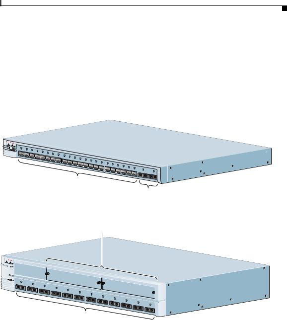
Figure 1-4 Catalyst 2900 LRE XL 10/100 and LRE Ports
9X
Catalyst 2900 |
LRE XL |
10/100 ports  LRE ports
10/100 Ports
48005
The 10/100 switch ports (see Figure 1-2 and Figure 1-4) can connect to any compatible network device up to 328 feet (100 meters) away:
•10BASE-T-compatible devices, such as workstations, Cisco IP Phones, and hubs through standard RJ-45 connectors and Category 3, 4, or 5 cabling
•100BASE-TX-compatible devices, such as high-speed workstations,
Cisco IP Phones, servers, hubs, routers, and other switches through standard RJ-45 connectors and Category 5 cabling
Note A Category 5 cable is required for 100BASE-TX traffic. A port operating at 10BASE-T can use Category 3 and 4 cables.
When connecting the switch to workstations, servers, routers, and Cisco IP Phones, be sure that the cable is a straight-through, twisted-pair cable. When connecting the switch to switches or hubs, use a crossover cable. Pinouts for the cables are described in Appendix B, “Connectors and Cable Specifications.”
The 10/100 switch ports can be explicitly set to operate in any combination of half duplex, full duplex, 10 Mbps, or 100 Mbps. These ports also can be set for speed and duplex autonegotiation, compliant with IEEE 802.3u. When set for autonegotiation, the port senses the speed and duplex settings of the attached device and advertises its own capabilities. If the connected device also supports autonegotiation, the switch port negotiates the best connection (that is, the fastest line speed that both devices support and full-duplex transmission if the attached device supports it) and configures itself accordingly.
|
Catalyst 2900 Series XL Hardware Installation Guide |
1-6 |
78-6461-03 |

Chapter 1 Product Overview
100BASE-FX Ports
The 10/100 ports on the Catalyst 2900 XL switches provide protocol support for Cisco IP Phones and per-port priority override. Refer to the Catalyst 2900 Series XL and Catalyst 3500 Series XL Software Configuration Guide for more information about these features.
Cisco IP Phones—connected to the 10/100 port—must be connected to an AC power source. Unlike the 3524-PWR XL switch, the Catalyst 2900 XL switches do not provide inline power.
For more info on the Catalyst 3524-PWR XL switch, refer to the
Catalyst 3500 Series XL Hardware Installation Guide.
100BASE-FX Ports
The 100BASE-FX ports use 10/125or 62.5/125-micron multimode fiber-optic cabling. The connection distances between the switch and the attached device can be as follows:
•If the switch port and the port on the attached device are configured for half-duplex operation, the connection can be up to 1352 feet (412 meters).
•If the switch port and the port on the attached device are configured for full-duplex operation, the connection can be over distances of up to 6562 feet (2 kilometers).
Long-Reach Ethernet Ports
The Long-Reach Ethernet (LRE) ports (Figure 1-4) use one RJ-21 connector to connect up to 24 Cisco 575 LRE customer premises equipment (CPE) devices though unstructured wiring, such as existing telephone lines. The link between the LRE switch port and each CPE device can reach speeds of up to 15 Mbps (full duplex) and distances of up to 4921 feet (1500 meters).
The default mode for each LRE port is speed autonegotiation, half duplex operation. For information about configuring the LRE ports, refer to the Catalyst 2900 Series XL and Catalyst 3500 Series XL Software Configuration Guide.
For more information about the Cisco 575 LRE CPE, refer to the Cisco 575 LRE CPE Hardware Installation Guide.
|
|
Catalyst 2900 Series XL Hardware Installation Guide |
|
|
|
|
|
||
|
78-6461-03 |
|
|
1-7 |
|
|
|

Chapter 1 Product Overview
100BASE-FX Ports
If telephone services, such as voice or integrated services digital network (ISDN), use the same cabling as LRE traffic, the LRE port must be connected to the patch panel through a basic telephone service, also known as plain old telephone service (POTS) splitter. The splitter routes LRE data (high-frequency) and voice (low-frequency) traffic from the telephone line to the switch and private branch exchange (PBX) switch or public-switched telephone network (PSTN)
If the other telephone services are connected through a private branch exchange (PBX) switch, a Cisco LRE 48 POTS Splitter can be used. The PBX routes voice traffic to private telephone networks and the public system telephone network (PSTN). For more information about the Cisco LRE 48 POTS Splitter (PS-1M-LRE-48), refer to the Installation Notes for the Cisco LRE 48 POTS Splitter.
If the installation does not have a PBX, a homologated POTS splitter is required to directly connect to the PSTN. For more information about homologated POTS splitters, contact your Cisco sales representative.
Note If a connection to a phone network is not required at all, a splitter is not needed, and the switch can connect directly to the patch panel.
Expansion Slots
The expansion slots (see Figure 1-2) are for the Catalyst 2900 XL hot-swappable modules. Each module port is internally switched to other switch ports and is managed through the switch management interfaces.
Table 1-1 lists the modules that the expansion slots support.
Table 1-1 Expansion Modules
|
|
|
Module Type |
Model Number |
|
|
|
|
|
|
|
|
|
|
|
|
10/100 Ethernet |
WS-X2914-XL |
||
|
|
|
|
WS-X2914-XL-V |
||
|
|
|
|
WS-X2922-XL |
||
|
|
|
|
|
|
|
|
|
|
100 BASE-FX |
WS-X2922-XL-V |
||
|
|
|
|
WS-X2924-XL-V |
||
|
|
|
|
|
|
|
|
|
Catalyst 2900 Series XL Hardware Installation Guide |
||||
|
|
|||||
1-8 |
|
|
|
78-6461-03 |
|
|
|
|
|
|
|||

Chapter 1 Product Overview
100BASE-FX Ports
Table 1-1 Expansion Modules (continued)
Module Type |
Model Number |
|
|
1Ethernet Gigabit |
WS-X2931-XL |
ATM |
WS-X2971-XL |
|
WS-X2972-XL |
|
WS-X2951-XL |
|
WS-X2961-XL |
|
|
1.Accommodates modules WS-G5484 =, WS-G5486 =, and WS-X3500-XL=
These modules automatically configure themselves when you insert them in expansion slots and tighten the thumb screws. A power-on self-test (POST) verifies that the module is working properly before it starts forwarding packets.
Modules WS-X2914-XL and WS-X2922-XL support 2048 MAC addresses. If you install one of these modules in a 2924M XL or Catalyst 2912MF XL switch (both supporting 8192 MAC addresses), the module fails POST. You can start the module by restarting the switch with the module installed. After the restart, the switch address capacity is reduced to 2048 MAC addresses.
See the Catalyst 2900 Series XL Modules Installation Guide and the
Catalyst 2900 Series XL ATM Modules Installation and Configuration Guide for detailed information on expansion modules for Catalyst 2900 series XL switches.
LEDs
You can use the switch LEDs to monitor switch activity and its performance. Figure 1-5, Figure 1-6, and Figure 1-7 show the location of the LEDs and the Mode button that you use to select a port mode. Changing a port mode changes the information provided by each port LED.
All of the LEDs described in this section except the utilization meter (UTL) are visible on the Cluster Management Suite (CMS) window and, if the switch is a cluster member, on the CMS Cluster Manager window. The Catalyst 2900 Series XL and Catalyst 3500 Series XL Software Configuration Guide describes how to use CMS to manage standalone or individual switches and how to use cluster management software to manage switch clusters].
|
|
Catalyst 2900 Series XL Hardware Installation Guide |
|
|
|
|
|
||
|
78-6461-03 |
|
|
1-9 |
|
|
|

100BASE-FX Ports
Figure 1-5 Catalyst 2912 XL, 2924 XL, and 2924C XL LEDs
10/100 port LEDs
System LED 


Port mode LEDs 
MODE
Mode RPS
button LED
Figure 1-6 Catalyst 2912MF XL and 2924M XL LEDs
10BASE-FX port LEDs
Chapter 1 Product Overview
47288
MODE |
System LED |
RPS LED |
Expansion slot status LED |
Port mode LED |
Mode button |
Catalyst 2900 Series XL Hardware Installation Guide
1-10 |
78-6461-03 |
|
|
Loading...