


7576
Table of contents
 Loading...
Text Part Number: 78-1895-04
Customer Order Number: DOC-781895=
Cisco 7513, Cisco 7513-MX, and
Cisco 7576 Card Cage and Backplane
Assembly Replacement Instructions
Product Numbers: MAS-7513CDCAGE= (Cisco 7513), MAS-7513MX-CDCAGE=
(Cisco 7513-MX), MAS-7576CDCAGE= (Cisco 7576)
This publication provides the procedures to replace the card cage and backplane assembly in the
Cisco 7513, Cisco 7513-MX, and Cisco 7576 routers. The card cage and backplane assembly for the
Cisco 7513, Cisco 7513-MX, and Cisco 7576 chassis can be replaced in the field. The assembly is a
single field-replaceable unit (FRU) that requires replacement by a Cisco-certified service provider
only.
This publication assumes you have already performed troubleshooting on your chassis and system
and determined that this replacement is required.
Document Contents
This publication includes the following sections:
• Product Overview, page 2
• Installation Safety, ESD Precautions, and Tools Required, page 5
• Removing and Replacing Processor Modules, page 9
• Removing Power Supplies, page 12
• Removing the Old Card Cage and Backplane Assembly, page 14
• Exchanging the EEPROM Devices, page 16
• Installing the New Card Cage and Backplane Assembly, page 18
• Replacing Power Supplies, page 20
• Checking the System, page 21
• Port and Slot Configuration Worksheet, page 23
• Cisco Connection Online, page 25
Corporate Headquarters
Cisco Systems, Inc.
170 West Tasman Drive
San Jose, CA 95134-1706
USA
Copyright © 1999
Cisco Systems, Inc.
All rights reserved.
1
Product Overview
Caution Before replacing the card cage and backplane assembly, read the “Safety Guidelines”
section on page 7. The specific procedures for removing and installing the card cage and backplane
assembly might require two people to perform.
Product Overview
The Cisco 7513, Cisco 7513-MX, and Cisco 7576 card cage holds the processor modules used by
the system. Figure 1 shows the rear view of the system.
Thecardcageandbackplaneare one assembly.The Cisco7513 and Cisco 7513-MXinclude the card
cage, backplane, dual arbiter, chassis interface, and the electrically erasable programmable
read-only memory (EEPROM) devicethat contains the system MAC addresses. The dual arbiter and
chassis interface are printed circuit boards that are attached to the rear of the backplane. The dual
arbiter and chassis interface are replaced when the card cage and backplane assembly is replaced.
The Cisco 7576 is a dual independent router system that includes two dual arbiters, two chassis
interfaces, and two EEPROM devices.
Note You must transfer the EEPROMdevice from your old card cage tothe new card cage for your
system to retain all of its MAC addresses. You must then install thenew EEPROM device on the old
card cage before you return the old card cage to Cisco. This procedure only applies if you are
replacing an equivalent card cage. It does not apply if you are upgrading a Cisco 7513 to a
Cisco 7576.
2 Cisco 7513, Cisco 7513-MX, and Cisco 7576 Card Cage and Backplane Assembly Replacement Instructions
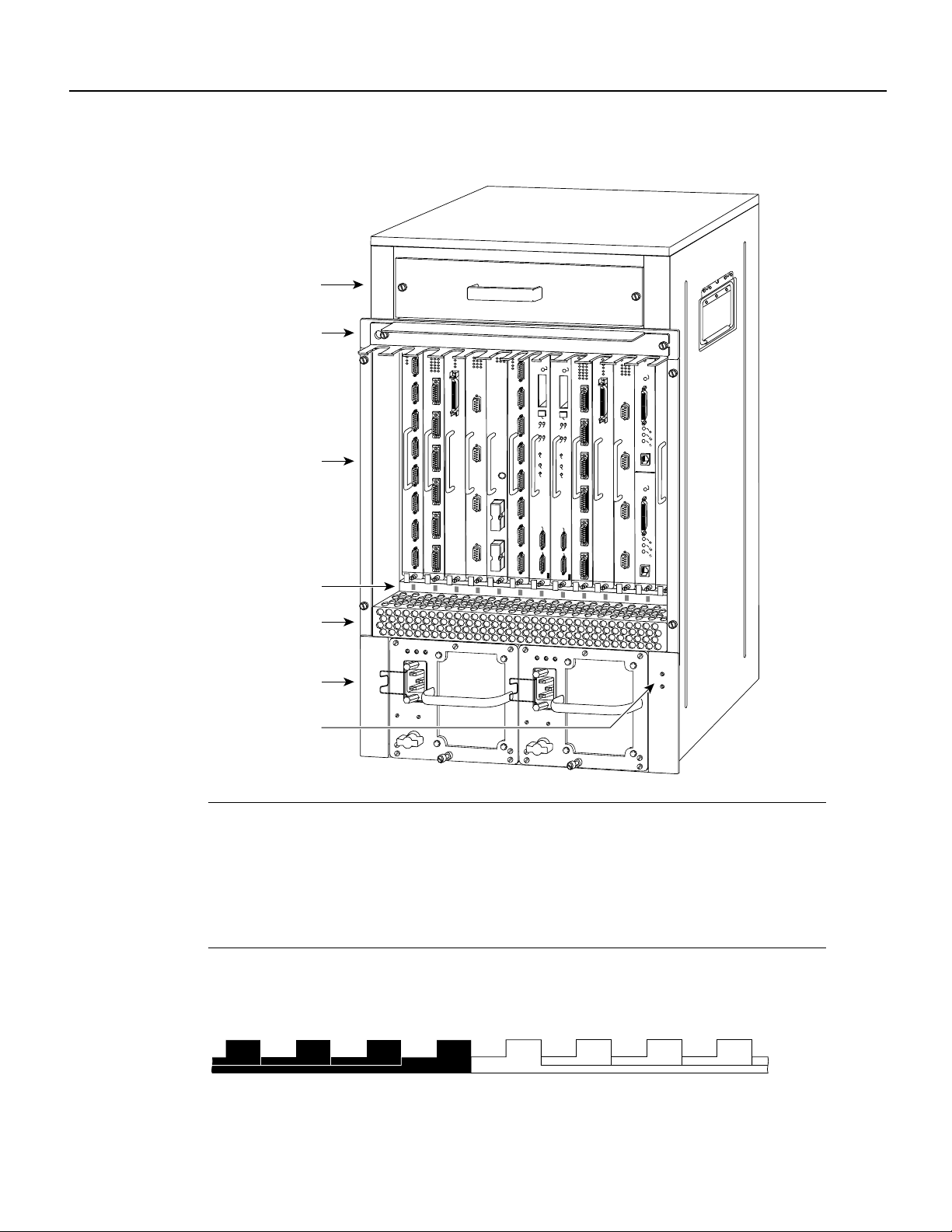
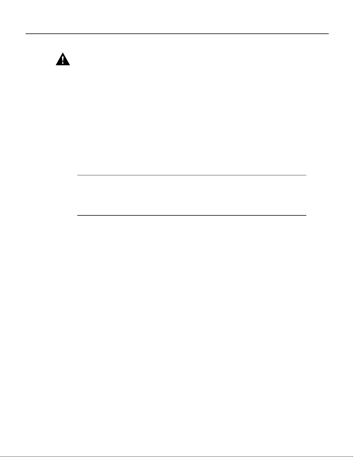
Figure 1 Cisco 7513, Cisco 7513-MX, and Cisco 7576—Rear-Panel View
Blower module
Product Overview
Cable-management
bracket
Card cage and
processor modules
Interface processor
slot numbering
scheme
Air intake vent
Power supplies
Chassis grounding
receptacles
POWER
A
NORMAL
NORMAL
EJECT
EJECT
SLOT 1
SLOT 0
SLOT 1
SLOT 0
MASTER
SLAVE
MASTER
SLAVE
SLAVE/MASTER
SLAVE/MASTER
CPU HALT
CPU HALT
RESET
RESET
AUX.
AUX.
ROUTE SWITCH PROCESSOR 2
ROUTE SWITCH PROCESSOR 2
CONSOLE
CONSOLE
AC
FAN
OUTPUT
OK
OK
FAIL
I
0
AC
FAN
OUTPUT
OK
OK
FAIL
I
0
ENABLE
ENABLE
POWER
B
14868
Note The Cisco 7513, Cisco 7513-MX, and Cisco 7576 use the same chassis, power supplies,
accessories, and slot numbering scheme. The Cisco 7513 or Cisco 7513-MX chassis contains a
single router that uses slot 0 though slot 12. The Cisco 7576 chassis contains two routers. Router A
uses slot 0 through slot 6, androuter B usesslot 7 throughslot 12. SeeFigure 2 for an enlarged view
of the Cisco 7576 interface processor slot numbering scheme. The Cisco 7513-MX backplane
includes connectors for time-divisionmutliplexing (TDM)-compatible hardware.These connectors
allow you to connect the Cisco 7513-MX to future TDM hardware as it becomes available.
Figure 2 Enlarged View of the Cisco 7576 Interface Processor Slot Numbering Scheme
3 4 5 6
7576 ROUTER A
RSP
RSP 7576 ROUTER B
9 1087
Cisco 7513, Cisco 7513-MX, and Cisco 7576 Card Cage and Backplane Assembly Replacement Instructions 3
14846
Product Overview
Note To provide a viewable image, slot numbers 0, 1, 2, 11, and 12 are not shown in Figure 2. The
slot numbering scheme uses color coding to assist in identifying routers and CyBus assignments.
Refer to the “Identifying Cisco 7576 Independent Routers and CyBuses” section in the Cisco 7500
Series Installation and ConfigurationGuide for detailed information on the slot numbering scheme.
Figure 3 shows the location of the dual arbiter and chassis interface on the rear of the Cisco 7513
and Cisco 7513-MX backplane.
Figure 3 Location of the Dual Arbiter and Chassis Interface on the Rear of the
Cisco 7513 and Cisco 7513-MX Backplane
Dual arbiter
or turbo arbiter
Chassis
interface
H3101
4 Cisco 7513, Cisco 7513-MX, and Cisco 7576 Card Cage and Backplane Assembly Replacement Instructions
Installation Safety, ESD Precautions, and Tools Required
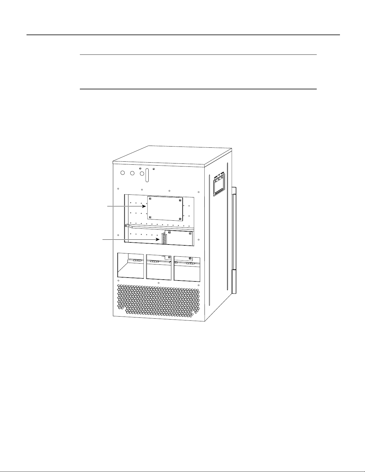
Figure 4 shows the location of the Cisco 7576 dual arbiters and chassis interfaces on the rear of the
backplane.
Figure 4 Location of the Cisco 7576 Dual Arbiters and Chassis Interfaces on the Rear
of the Backplane
Dual arbiters
Chassis
interfaces
Note When you view the rear of the card cage, the dual arbiter and chassis interface on the right
B
B
A
A
14866
side are used with router A, and the dual arbiter and chassis interface on the left side are used with
router B.
Installation Safety, ESD Precautions, and Tools Required
Before you begin replacing the backplane and card cage assembly, review the safety guidelines in
this section to avoid injuring yourself or damaging the equipment. This section also lists the tools
and parts you need to perform this procedure.
Cisco 7513, Cisco 7513-MX, and Cisco 7576 Card Cage and Backplane Assembly Replacement Instructions 5

Installation Safety, ESD Precautions, and Tools Required
Safety Warnings
Safety warningsappear throughout this publication in procedures that,if performed incorrectly,may
harm you. A warning symbol precedes each warning statement.
Warning This warning symbol means danger. You are in a situation that could cause bodily
injury. Before you work on any equipment, be aware of the hazards involved with electrical
circuitry and be familiar with standard practices for preventingaccidents. Tosee translations of the
warnings that appear in this publication, refer to the Regulatory Compliance and Safety
Information document that accompanied this device.
Waarschuwing Dit waarschuwingssymbool betekent gevaar. U verkeert in een situatie die
lichamelijk letsel kan veroorzaken. Voordat u aanenige apparatuur gaat werken,dient u zich bewust
te zijn van de bij elektrische schakelingen betrokken risico's en dient u op de hoogte te zijn van
standaard maatregelen om ongelukken te voorkomen. Voor vertalingen van de waarschuwingen die
in deze publicatie verschijnen, kunt uhet documentRegulatory Compliance and Safety Information
(Informatie over naleving van veiligheids- en andere voorschriften) raadplegen dat bij dit toestel is
ingesloten.
Varoitus Tämävaroitusmerkki merkitseevaaraa. Olettilanteessa, joka voijohtaa ruumiinvammaan.
Ennen kuin työskentelet minkään laitteiston parissa, ota selvää sähkökytkentöihin liittyvistä
vaaroista ja tavanomaisista onnettomuuksien ehkäisykeinoista. Tässä julkaisussa esiintyvien
varoitusten käännökset löydät laitteen mukana olevasta Regulatory Compliance and Safety
Information -kirjasesta (määräysten noudattaminen ja tietoa turvallisuudesta).
Attention Ce symbole d'avertissement indique un danger. Vous vous trouvez dans une situation
pouvant causer des blessures ou des dommages corporels. Avant de travailler sur un équipement,
soyez conscient des dangers posés par les circuits électriques et familiarisez-vous avec les
procédures couramment utilisées pour éviter les accidents. Pour prendre connaissance des
traductions d’avertissements figurant dans cette publication, consultez le document Regulatory
Compliance and Safety Information (Conformité aux règlements et consignes de sécurité) qui
accompagne cet appareil.
Warnung Dieses Warnsymbol bedeutet Gefahr. Sie befinden sich in einer Situation, die zu einer
Körperverletzungführen könnte. Bevor Sie mit der Arbeit an irgendeinem Gerät beginnen, seien Sie
sich der mit elektrischen Stromkreisen verbundenen Gefahren und der Standardpraktiken zur
Vermeidung von Unfällen bewußt. Übersetzungen der in dieser Veröffentlichung enthaltenen
Warnhinweise finden Sie im Dokument Regulatory Compliance and Safety Information
(Informationen zu behördlichen Vorschriften und Sicherheit), das zusammen mit diesem Gerät
geliefert wurde.
Avvertenza Questo simbolo di avvertenza indica un pericolo. La situazione potrebbe causare
infortuni alle persone. Prima di lavorare su qualsiasi apparecchiatura, occorre conoscere i pericoli
relativiai circuiti elettricied essere al correntedelle pratiche standard perla prevenzionedi incidenti.
La traduzione delle avvertenze riportate in questa pubblicazione si trova nel documento Regulatory
Compliance and Safety Information (Conformità alle norme e informazioni sulla sicurezza) che
accompagna questo dispositivo.
Advarsel Dette varselsymbolet betyr fare. Du befinner deg i en situasjon som kan føre til
personskade. Før du utfører arbeid på utstyr, må du vare oppmerksom på de faremomentene som
elektriskekretser innebærer, samtgjøre deg kjent med vanligpraksis når det gjelder åunngå ulykker.
Hvis du vil se oversettelser av de advarslene som finnes i denne publikasjonen, kan du se i
dokumentet Regulatory Compliance and Safety Information (Overholdelse av forskrifter og
sikkerhetsinformasjon) som ble levert med denne enheten.
6 Cisco 7513, Cisco 7513-MX, and Cisco 7576 Card Cage and Backplane Assembly Replacement Instructions

Aviso Este símbolo de aviso indica perigo. Encontra-se numasituação que lhe poderácausar danos
físicos. Antes de começar a trabalhar com qualquer equipamento, familiarize-se com os perigos
relacionados com circuitos eléctricos, e com quaisquer práticas comuns que possam prevenir
possíveis acidentes. Para ver as traduções dos avisos que constam desta publicação, consulte o
documento Regulatory Compliance and Safety Information (Informação de Segurança e
Disposições Reguladoras) que acompanha este dispositivo.
¡Advertencia! Este símbolo de aviso significa peligro. Existe riesgo para su integridad física.
Antes de manipular cualquier equipo, considerar los riesgos que entraña la corriente eléctrica y
familiarizarse con los procedimientos estándar de prevenciónde accidentes. Para ver una traducción
de las advertencias que aparecen en esta publicación, consultar el documento titulado Regulatory
Compliance and Safety Information (Información sobre seguridad y conformidad con las
disposiciones reglamentarias) que se acompaña con este dispositivo.
Varning! Denna varningssymbol signalerar fara. Du befinner dig i en situation som kan leda till
personskada. Innan du utför arbete på någon utrustning måste du vara medveten om farorna med
elkretsar och känna till vanligt förfarande för att förebygga skador. Se förklaringar av de varningar
som förkommer i denna publikation i dokumentet Regulatory Compliance and Safety Information
(Efterrättelse av föreskrifter och säkerhetsinformation), vilket medföljer denna anordning.
Safety Guidelines
Followthese guidelines to ensure your safetyand protect the equipment. This listis not inclusiveof
all potentially hazardous situations, so be alert.
Safety Guidelines
Safety with Electricity
• Never try to lift the chassis by yourself; two people are required to lift a Cisco 7513,
Cisco 7513-MX, or Cisco 7576.
• Always disconnect all power cords and interface cables before moving the chassis.
• Keep tools and chassis components away from walk areas.
• Do not work alone if potentially hazardous conditions exist.
• Do not perform any action that creates a potential hazard to people or makes the equipment
unsafe.
• Carefully examine your work area for possible hazards such as moist floors, ungrounded power
extension cables, and missing safety grounds.
Follow these basic guidelines when working with any electrical equipment:
• Before beginning any procedures requiring access to the chassis interior, locate the emergency
power-off switch for the room in which you are working.
• Disconnect all power and external cables before moving a chassis.
• Do not work alone if potentially hazardous conditions exist.
• Never assume that power is disconnected from a circuit; always check.
• Do not perform any action that creates a potential hazard to people or makes the equipment
unsafe.
• Carefully examine your work area for possible hazards such as moist floors, ungrounded power
extension cables, and missing safety grounds.
Cisco 7513, Cisco 7513-MX, and Cisco 7576 Card Cage and Backplane Assembly Replacement Instructions 7
Installation Safety, ESD Precautions, and Tools Required
In addition, use the guidelines that follow when working with any equipment that is connected to
telephone wiring or other network cabling:
• Never install telephone wiring during a lightning storm.
• Never install telephone jacks in wet locations unless the jack is specifically designed for wet
locations.
• Never touch uninsulated telephone wires or terminals unless the telephone line is disconnected
at the network interface.
• Use caution when installing or modifying telephone lines.
Preventing Electrostatic Discharge Damage
Electrostatic discharge (ESD) damage, which can occur when electronic boards or components are
handled improperly, can result in complete or intermittent failures.
Following are guidelines for preventing ESD damage:
• Always use an ESD-preventive wrist strap or ankle strap and ensure that it makes good skin
contact.
• When removing or installing an ESD-sensitive component, connect the equipment end of a
ground strap to an unpainted surface of the chassis, such as the chassis frame.
• If you are returning a replaced part to the factory, immediately place it in a static shielding bag
• The wrist strap only protects the board from ESDvoltages on the body; ESD voltages on clothing
Warning For safety, periodically check the resistance value of the antistatic strap. The
measurement should be between 1 and 10 megohms.
Tools Required
You need the following tools to install or replace the backplane and card cage assembly:
• 1/4-inch flat-blade screwdriver to loosen the captive screws on the power supplies and card cage
• Number 1 Phillips or 1/4-inch, flat-blade screwdriver to remove any blank processor module
• Spare card cage assembly—includes the card cage with the chassis interface (attached) and dual
• ESD-preventive wrist strap
• Small piece of masking or clear cellophane tape to mark the new EEPROM device
• Antistatic packaging in which the old card cage assembly should be placed
to avoid ESD damage to the board.
can still cause damage.
carriers (fillers) and to tighten the captive installation screws that secure the processor module in
its slot
arbiter (attached)
8 Cisco 7513, Cisco 7513-MX, and Cisco 7576 Card Cage and Backplane Assembly Replacement Instructions
Loading...