


AT10.1 SERIES
Operating and Service Instructions
MICROPROCESSOR-CONTROLLED
FLOAT BATTERY CHARGER
SINGLE PHASE INPUT
GROUP I
(6 - 25 Adc)

HOW TO READ THE AT10.1 MODEL NUMBER
GROUP I RATINGS (6-25 Adc)
Your AT10.1 model number is coded to describe the options that are included. Please find the model number on the data nameplate and write it in the spaces provided below. Then follow the chart to determine the configuration of your battery charger.
AT10
A |
B |
C |
D |
E |
F |
K |
L |
M |
N |
P |
Q |
R |
|
DESCRIPTION |
CODE |
FEATURE |
|
A |
SERIES |
AT10 |
AT10.1 CHARGER |
|
|
NOMINAL |
012 |
12 Vdc |
|
|
|
|
||
B |
024 |
24 Vdc |
||
DC OUTPUT |
||||
|
|
|||
048 |
48 Vdc |
|||
|
VOLTAGE |
|||
|
|
130 |
130 Vdc |
|
|
|
006 |
6 Adc |
|
|
|
|
|
|
|
NOMINAL |
012 |
12 Adc |
|
C |
DC OUTPUT |
016 |
16 Adc |
|
|
CURRENT |
|
|
|
|
020 |
20 Adc |
||
|
|
|||
|
|
|
|
|
|
|
025 |
25 Adc |
|
|
|
U |
UNFILTERED |
|
D |
FILTERING |
F |
FILTERED |
|
|
|
|
|
|
|
|
E |
ELIMINATOR |
|
|
|
120 |
120 Vac 60 Hz 1 |
|
|
|
208 |
208 Vac 60 Hz 1 |
|
|
AC INPUT |
240 |
240 Vac 60 Hz 1 |
|
E |
480 |
480 Vac 60 Hz 2 |
||
|
VOLTAGE |
|
|
|
|
220 |
220 Vac 50/60 Hz 3 |
||
|
|
|||
|
|
380 |
380 Vac 50/60 Hz 3 |
|
|
|
416 |
416 Vac 50/60 Hz 3 |
|
DESCRIPTION |
CODE |
FEATURE |
|
|
CIRCUIT |
S |
STANDARD |
|
F |
BREAKER |
|
|
|
M |
MEDIUM AIC |
|||
RATING |
||||
|
|
|
||
|
H |
HIGH AIC |
||
|
(SEE TABLE) |
|||
|
|
|
|
|
K |
AUX ALARM |
AUX |
SUPPLIED |
|
RELAY BOARD |
XXX |
NOT SUPPLIED |
||
|
||||
|
|
|
|
|
|
|
|
|
|
L |
GROUND PAD |
G |
SUPPLIED |
|
|
|
|||
X |
NOT SUPPLIED |
|||
|
|
|||
|
|
|
|
|
|
|
|
|
|
M |
LIGHTNING |
L |
SUPPLIED |
|
ARRESTOR |
X |
NOT SUPPLIED |
||
|
||||
|
|
|
|
|
|
|
|
|
|
N |
FUNGUS |
F |
INCLUDED |
|
PROOFING |
X |
NOT INCLUDED |
||
|
||||
|
|
|
|
|
P |
STATIC |
S |
INCLUDED |
|
PROOFING |
X |
NOT INCLUDED |
||
|
||||
|
|
|
|
|
Q |
NOT USED |
X |
|
|
R |
CANADIAN |
C |
BILINGUAL LABELING |
|
|
|
|
|
DESCRIPTION |
CODE |
FEATURE |
DESCRIPTION |
CODE |
FEATURE |
1 - 120/208/240 Vac multi-tap input - Unit is wired and shipped from factory at specified voltage.
2 - 480 Vac input requires addition of medium or high ampere interrupting capacity circuit breakers. 3 - Special order - Please consult factory for availability.
INPUT AND OUTPUT CIRCUIT BREAKER INTERRUPTING RATINGS
CODE |
TYPE |
AC RATINGS |
DC RATINGS |
|
(ALL INPUT VOLTAGES) |
(125 Vdc) |
|||
|
|
|||
S |
STANDARD |
240 Vac: 10,000 AIC |
10,000 AIC 4 |
|
5,000 AIC 5 |
||||
M |
MEDIUM AIC |
240 Vac: 25,000 AIC |
10,000 AIC |
|
480 Vac: 18,000 AIC |
||||
|
|
|
||
|
|
|
|
|
H |
HIGH AIC |
240 Vac: 65,000 AIC |
25,000 AIC |
|
480 Vac: 25,000 AIC |
||||
|
|
|
||
|
|
|
|
|
|
|
4 - Rating applies to 130Vdc 16-25 Adc units. |
||
|
|
5 - Approximate rating applies to all other units. |
||
NOTE:
The model number listed on the charger data nameplate does not include any field-installed options. Also, certain accessories are not included in the model number, even if they are shipped with the charger. Check off below any accessories that were included, or that you install yourself.
Enclosure drip shield assembly |
|
NEMA-4/12/13 type enclosure |
Floor mounting brackets |
|
Pad lock for front panel door |
Rack mounting brackets |
|
External temperature compensation probe |
Cabinet heater assembly |
|
DNP3 Level 2 / Modbus communications module |
Please find the serial number on the data nameplate and record it here:

IMPORTANT SAFETY INSTRUCTIONS
1.Before using this equipment, read all instructions and cautionary markings on: A) this equipment, B) battery, and C) any other equipment to be used in conjunction with this equipment.
2.This manual contains important safety and operating instructions, and therefore should be filed for easy access.
3.Remove all jewelry, watches, rings, etc. before proceeding with installation or service.
4.Do not touch any uninsulated parts of this equipment, especially the input and output connections, as there is the possibility of electrical shock.
5.During normal operation, batteries may produce explosive gas. Never smoke, use an open flame, or create arcs in the vicinity of this equipment or the battery.
6.Maintain at least 6in / 152mm clearance from all obstructions on the top, bottom and sides of this equipment. Allow sufficient clearance to open the front panel for servicing.
7.Turn this equipment off before connecting or disconnecting the battery to avoid a shock hazard and/or equipment damage.
8.Connect or disconnect the battery only when the battery charger is off to prevent arcing or burning.
9.De-energize all ac and dc inputs to the battery charger before servicing.
10.Do not operate battery charger if it has been damaged in any way. Refer to qualified service personnel.
11.Do not disassemble battery charger. Only qualified service personnel should attempt repairs. Incorrect reassembly may result in explosion, electrical shock, or fire.
12.Do not install the battery charger outdoors, or in wet or damp locations unless specifically ordered for that environment.
PLEASE READ AND FOLLOW ALL SAFETY INSTRUCTIONS
i

TABLE OF CONTENTS
QUICK OPERATION .................................................................................................. |
|
Back Cover |
|
HOW TO READ THE AT10.1 MODEL NUMBER .......................................... |
Inside Front Cover |
||
IMPORTANT SAFETY INSTRUCTIONS ...................................................................................... |
|
i |
|
1 Receiving and Installing the AT10.1 Battery Charger |
|
|
|
1.1 |
Storing the AT10.1 ................................................................................................. |
|
2 |
1.2 |
Reporting shipping damage ................................................................................... |
|
2 |
1.3 |
Unpacking and inspecting the AT10.1 ................................................................... |
|
2 |
|
Inspection checklist ................................................................................................ |
|
2 |
1.4 |
Moving the AT10.1 ................................................................................................. |
|
3 |
|
Enclosure type and weight table ............................................................................ |
|
3 |
1.5 |
Mounting the AT10.1 .............................................................................................. |
|
3 |
1.5.1 Wall-Mounting the AT10.1 ............................................................................... |
|
4 |
|
1.5.2 Floor-Mounting the AT10.1 .............................................................................. |
|
6 |
|
1.5.3 Rack-Mounting the AT10.1 .............................................................................. |
|
8 |
|
1.6 |
Changing transformer taps................................................................................... |
|
10 |
1.7 |
Making the ac input connections .......................................................................... |
|
12 |
1.8 |
Making the dc output connections........................................................................ |
|
14 |
1.9 |
Wiring the AT10.1 for remote sensing.................................................................. |
|
16 |
1.10 |
Wiring to the remote alarm contacts .................................................................... |
|
18 |
|
Auxiliary Relay Board (optional) ........................................................................... |
|
19 |
1.11 |
Installing the temperature compensation assembly (optional) ............................. |
|
20 |
|
Using temperature compensation ........................................................................ |
|
22 |
2 Operating the AT10.1 Battery Charger |
|
|
|
2.1 |
Starting the AT10.1 |
|
|
2.1.1 Understanding the start-up sequence............................................................ |
|
24 |
|
2.1.2 Checking the installation ................................................................................ |
|
24 |
|
2.1.3 Starting the AT10.1 ........................................................................................ |
|
24 |
|
|
Using the digital meter ................................................................................... |
|
24 |
|
Factory settings table..................................................................................... |
|
25 |
2.2 |
Using the AT10.1 front panel features |
|
|
2.2.1 If the meter displays an error message ......................................................... |
|
26 |
|
2.2.2 Selecting the meter mode.............................................................................. |
|
26 |
|
2.2.3 Selecting the Float or Equalize mode ............................................................ |
|
27 |
|
2.2.4 Choosing the Equalize method...................................................................... |
|
27 |
|
|
Manual Timer method .................................................................................... |
|
27 |
|
Manual Equalize method ............................................................................... |
|
28 |
|
Auto-Equalize Timer method ......................................................................... |
|
28 |
2.2.5 Testing the front panel indicators & Summary Alarm Relays |
........................29 |
||
2.2.6 Testing the Auxiliary Relay Board.................................................................. |
|
29 |
|
2.2.7 Interpreting the alarm indicators .................................................................... |
|
29 |
|
ii

TABLE OF CONTENTS
2.3Setting the AT10.1 parameters
|
2.3.1 Understanding parameter settings ................................................................. |
30 |
|
2.3.2 Setting the Float and Equalize voltages......................................................... |
31 |
|
2.3.3 Setting the Equalize timer .............................................................................. |
32 |
|
2.3.4 Setting the Alarms.......................................................................................... |
32 |
|
Setting the high and low dc voltage alarms ................................................... |
33 |
|
Adjusting ground detection sensitivity ............................................................ |
34 |
|
Disabling the ground detection alarm ............................................................ |
35 |
|
2.3.5 Setting the current limit value......................................................................... |
35 |
|
2.3.6 Enabling the high dc voltage shutdown feature ............................................. |
36 |
|
2.3.7 Adjusting the Voltmeter accuracy .................................................................. |
37 |
|
2.3.8 Using the Low Level Detector (LLD) .............................................................. |
38 |
|
2.3.9 Using the front panel security feature ............................................................ |
39 |
2.4 |
Performing routine maintenance .......................................................................... |
40 |
|
Sample preventive maintenance procedure .................................................. |
42 |
3 Servicing the AT10.1 Battery Charger |
|
|
3.1 A step-by-step troubleshooting procedure ........................................................... |
44 |
|
3.2 Interpreting front panel error messages ............................................................... |
45 |
|
3.3 Using the troubleshooting chart............................................................................ |
48 |
|
3.4 Troubleshooting chart begins on .......................................................................... |
49 |
|
3.5 |
Replacing defective components.......................................................................... |
58 |
3.6 |
Ordering replacement parts .................................................................................. |
64 |
|
Replacement parts tables (begin on).................................................................... |
64 |
APPENDIX A: AT10.1 Performance Specifications................................................................ |
70 |
|
APPENDIX B: Field Installable Accessories ........................................................................... |
71 |
|
APPENDIX C: Standard Drawings |
|
|
Standard NEMA-1 Enclosure Outline (Style-586) .......................................................... |
72 |
|
Standard NEMA-1 Enclosure Outline (Style-594) .......................................................... |
73 |
|
Optional Enclosure Outline Drawings (with penthouse and/or drip shield) .................... |
74 |
|
Internal Component Layout Detail w/Common Options ................................................. |
76 |
|
Instrument Panel Detail w/Optional Auxiliary Relay PC Board ...................................... |
78 |
|
Schematic - AT10.1 Group I Battery Charger - Standard w/o Options .......................... |
80 |
|
Schematic - AT10.1 Group I Battery Charger - with Common Options ......................... |
82 |
|
Connection Diagram - AT10.1 Group I Battery Charger - Standard w/o Options .......... |
84 |
|
Connection Diagram - AT10.1 Group I Battery Charger - with Common Options ......... |
86 |
|
APPENDIX D: Recommended Float / Equalize Voltages ....................................................... |
88 |
|
APPENDIX E: DNP3 Level 2 / Modbus Communications Module......................................... |
89 |
|
APPENDIX F: UL Data ............................................................................................................... |
89 |
|
CUSTOMER NOTES (manual specifications)............................................................................. |
90 |
|
iii

TABLE OF CONTENTS
1. RECEIVING THE AT10.1
1.1. STORING THE AT10.1
If you store the AT10.1 for more than a few days before installation, you should store it in its original shipping container, and in a temperature controlled, dry climate. Ambient temperatures of 32 to 122° F / 0 to 50° C are acceptable. Storage should not exceed 2 years due to the limited shelf life of the dc filter capacitors when they are not in service.
1.2. REPORTING SHIPPING DAMAGE
If, on delivery of the AT10.1 or related goods, you discover any damage or shortage, make notation on all copies of delivering carrier's delivery receipt before signing, and notify the delivery person of your findings. If loss or damage is discovered after delivery, notify delivering carrier immediately and request an inspection. The manufacturer does not assume any liability for damage during transportation or handling.
Should the goods require an inspection by or return to the manufacturer, please contact your sales representative for further instructions. Any returned material must be properly packed in compliance with shipping regulations. It is preferable to use the original shipping materials if possible. Mark the outside of the shipping container with the Return Material Authorization (RMA) number issued by the manufacturer.
1.3. UNPACKING AND INSPECTING THE AT10.1
Carefully remove all shipping materials from the AT10.1. Remove the AT10.1 from the shipping pallet for inspection. Save all shipping materials until you are sure that there is no shipping damage.
Once the AT10.1 is unpacked, inspect the unit for possible shipping damage, using the checklist below. If shipping damage has occurred, please refer to section 1.2 on this page for proper reporting.
INSPECTION CHECKLIST
oEnclosure exterior and interior are not marred or dented.
oThere is no visible damage to exterior or interior components.
oAll internal components are secure.
oPrinted circuit boards are firmly seated on their standoffs.
oAll hardware is tight.
oAll wire terminations are secure.
oThe User's Manual is included.
oYou received all items on the packing list.
2

RECEIVING THE AT10.1
1.4. MOVING THE AT10.1
Once you have established that the AT10.1 is undamaged, identify the enclosure style and weight of your unit. Refer to the table below.
AT10.1 Enclosure Type And Shipping Weight Table
Group I Cabinet Styles (586 / 594)
Output |
|
|
Ampere Rating |
|
|
|||
Voltage |
6 Adc |
126 Adc |
|
16 Adc |
|
20 Adc |
25 Adc |
|
|
|
|
|
|
|
|
||
12 |
Vdc |
Style-586 |
Style-586 |
Style-586 |
Style-586 |
Style-586 |
||
44 lbs |
44 lbs |
|
67 lbs |
|
67 lbs |
67 lbs |
||
|
|
20 kg |
20 kg |
|
30 kg |
|
30 kg |
30 kg |
|
|
|
|
|
|
|
||
|
|
Style-586 |
Style-586 |
Style-586 |
Style-586 |
Style-586 |
||
24 |
Vdc |
44 lbs |
58 lbs |
|
75 lbs |
|
75 lbs |
75 lbs |
|
|
20 kg |
26 kg |
|
34 kg |
|
34 kg |
34 kg |
|
|
|
|
|
|
|
||
|
|
Style-586 |
Style-586 |
Style-594 |
Style-594 |
Style-594 |
||
48 |
Vdc |
58 lbs |
75 lbs |
|
110 lbs |
|
110 lbs |
110 lbs |
|
|
26 kg |
34 kg |
|
50 kg |
|
50 kg |
50 kg |
|
|
|
|
|
|
|
||
|
|
Style-586 |
Style-594 |
Style-594 |
Style-594 |
Style-594 |
||
130 |
Vdc |
80 lbs |
147 lbs |
|
193 lbs |
|
193 lbs |
193 lbs |
|
|
36 kg |
67 kg |
|
88 kg |
|
88 kg |
88 kg |
|
|
|
|
|
|
|
|
|
NOTE: Actual unit is approximately 20 lbs / 9kg below listed shipping weight in table.
The Style-586 & 594 enclosures do not feature lifting eyes for moving. Instead, whenever possible move the unit with a forklift truck using the supplied shipping pallet. To hoist the unit into a wall-mount or rackmount location, use a heavy-duty sling applicable to the enclosure size and unit weight. To relocate the Style-586 & 594 enclosures, use the aforementioned sling on a hoist or forklift truck.
1.5. MOUNTING THE AT10.1
Chose the mounting method for the unit enclosure from the table below.
MANUAL |
MOUNTING METHOD |
ENCLOSURE |
||
SECTION |
Style-586 |
Style-594 |
||
|
||||
|
|
|
|
|
1.5.1 |
Wall-Mounting |
STANDARD |
STANDARD |
|
|
|
|
|
|
1.5.2 |
Floor-Mounting |
OPTIONAL |
OPTIONAL |
|
|
|
|
|
|
|
19in / 483mm Rack-Mounting |
OPTIONAL |
OPTIONAL |
|
1.5.3 |
|
|
|
|
23-24in / 584-610mm |
OPTIONAL |
OPTIONAL |
||
|
Rack-Mounting |
|||
|
|
|
||
|
|
|
|
|
3
INSTALLING THE AT10.1
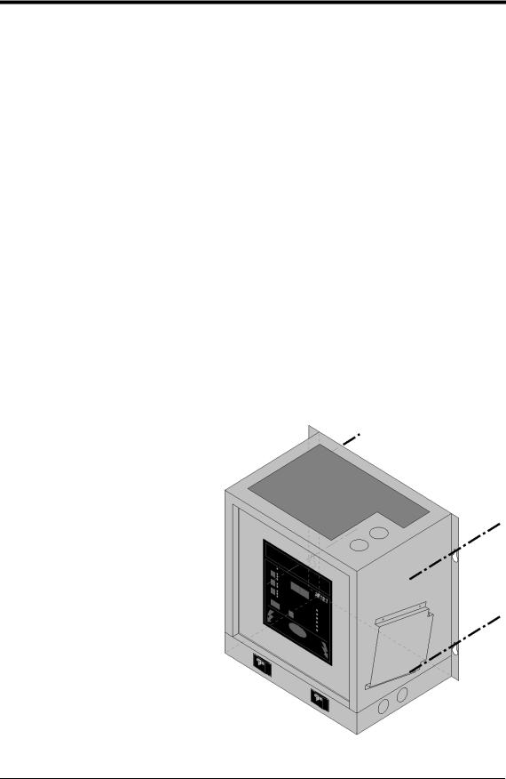
1.5.1.Wall-Mounting the AT10.1
Wall-mounting the AT10.1 battery charger is the standard way to install the Group I enclosures (Style-586/594). In planning for wall mounting of the AT10.1 consider the following:
1.The wall must be strong enough to properly support the weight of the AT10.1. See the Weight Table located in section 1.4 on page 3. The weight of your AT10.1 may be different from the table value, depending on options or accessories you ordered.
2.Select conduit entrances carefully. Use of the pref-fab knockouts on the sides or bottom of the enclosure will allow removal of the cabinet shroud (and internal access for servicing) without removal of unit from the wall.
3.The location:
∙Should be free of drips and splatter. If dripping liquids are a problem, install a drip shield kit (part number EI0191-00). For kit availability, see ordering information in Appendix B on page 71.
∙Should be between 32 and 122 °F / 0 and 50 °C, with relative humidity between 5 and 95% non-condensing.
∙Must be free of explosive materials.
4.Maintain at least 6in / 152mm of free air on top, bottom and both sides for cooling air.
5.Allow 36in / 914mm front clearance for operation and maintenance.
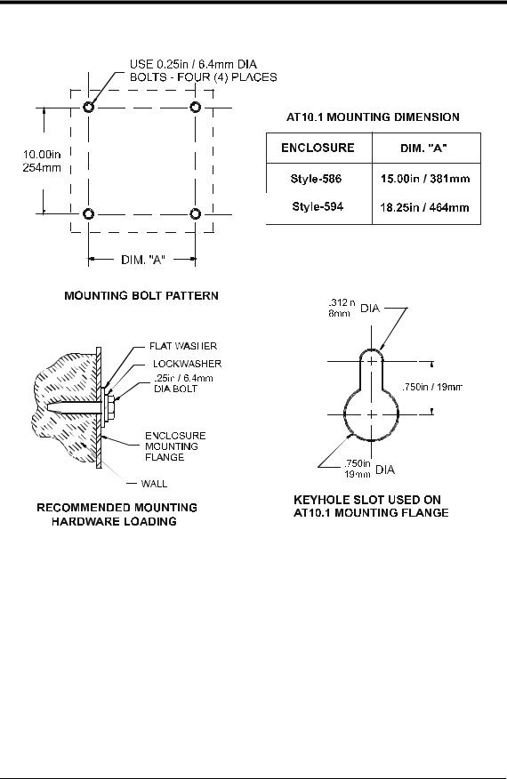
PROCEDURE
To wall-mount the AT10.1, install four (4)
.25in / 6.4mm bolts on the wall rated to support the AT10.1 weight plus a safety factor of at least 2 times. Place the AT10.1 on the bolts, add appropriate mounting hardware and tighten.
Reference the graphics on the next page. For more information, see Outline Drawings in Appendix C on page 72.
4
INSTALLING THE AT10.1
WALL-MOUNTING THE AT10.1 - GRAPHICS
5
INSTALLING THE AT10.1
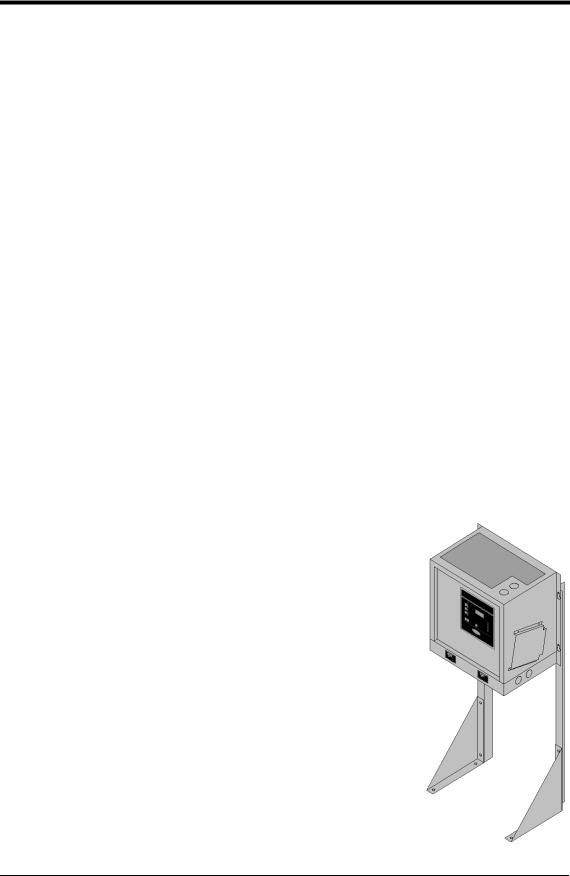
1.5.2.Floor-Mounting the AT10.1
To floor mount the AT10.1, you must use the floor mounting accessory kit (part number EI0192-00). For kit availability, see ordering information in Appendix B on page 71. The kit contains brackets that elevate the top of the AT10.1 approximately 47in / 1194mm above floor level, with provision for floor anchoring. The kit includes an instruction sheet (JA0083) showing assembly dimensions and mounting details.
You must locate the anchor-bolt holes at least 4.25in / 108mm from any wall, to allow clearance for the charger enclosure behind the mounting brackets. In addition, you must consider the following:
1.Placement of conduit entrances (use the knockouts on the sides or bottom of the charger to allow access for servicing without removing the unit from the mounting brackets).
2.The location:
∙Should be free of drips and splatter. If dripping liquids are a problem, install a drip shield kit (part number EI0191-00). For kit availability, see ordering information in Appendix B on page 71.
∙Should be between 32 and 122 °F / 0 and 50 °C, with relative humidity between 5 and 95% non-condensing.
∙Must be free of explosive materials.
3.Maintain at least 6in / 152mm of free air on top, bottom and both sides for cooling air.
4.Allow 36in / 914mm front clearance for operation and maintenance.
PROCEDURE
To floor-mount the AT10.1, follow the directions featured in instruction sheet (JA0083), included with your floormounting kit (part number EI0192-00). These instructions showing assembly dimensions and mounting details.
Place the AT10.1 assembly on the mounting bolts, add appropriate mounting hardware and tighten.
Reference the graphics on the next page.
6
INSTALLING THE AT10.1
FLOOR-MOUNTING THE AT10.1 - GRAPHICS
|
|
|
DIMENSION (in / mm) |
|
|
||
ENCLOSURE |
A |
|
B |
|
C |
|
D |
|
|
|
|||||
|
|
|
|
|
|
|
|
Style-586 |
16.50 / 419 |
|
46.63 / 1184 |
|
11.75 / 298 |
|
15.00 / 381 |
|
|
|
|
|
|
|
|
Style-594 |
19.75 / 502 |
|
47.75 / 1213 |
|
14.25 / 361 |
|
18.25 / 463 |
|
|
|
|
|
|
|
|
7

INSTALLING THE AT10.1
1.5.3.Rack-Mounting the AT10.1
The AT10.1 can be installed in most relay racks with standard EIA hole spacing (see the table below for the allowable combinations). The rack mounting kit (part number EI0193-00), includes mounting brackets and the necessary hardware to install one AT10.1 battery charger. The kit includes an instruction sheet (JA0091) showing installation details. For kit availability see ordering information in Appendix B on page 71.
When rack mounting the AT10.1, you must consider the following:
1.The rack must be strong enough to properly support the weight of the AT10.1. See the Weight Table located in section 1.4 on page 3.
2.Placement of conduit entrances (be sure the knockouts on the sides or bottom of the charger are accessible after the charger is rack-mounted).
3.The location:
∙Should be free of drips and splatter. If dripping liquids are a problem, install a drip shield kit (part number EI0191-00). For kit availability, see ordering information in Appendix B on page 71.
∙Should be between 32 and 122 °F / 0 and 50 °C, with relative humidity between 5 and 95% non-condensing.
∙Must be free of explosive materials.
4.Maintain at least 6in / 152mm of free air on top, bottom and both sides for cooling air.
5.Allow 36in / 914mm front clearance for operation and maintenance.
PROCEDURE
To rack mount the AT10.1, first install the brackets onto the rack. Second, mount the AT10.1 onto the rack-mounting brackets using the hardware supplied. Provide at least 6in / 152mm of air space above and below the AT10.1 in the rack for cooling. You do not need to modify the AT10.1 enclosure. Rack-mount outline dimensions are shown on the next page.
CHARGER RATING |
|
RACK WIDTH |
|
||
Vdc |
|
Adc |
|
|
|
|
19in / 483mm |
23in / 584mm |
24in / 610mm |
||
|
|
|
|
|
|
12 Vdc |
|
all |
Yes |
Yes |
Yes |
|
|
|
|
|
|
24 Vdc |
|
all |
Yes |
Yes |
Yes |
|
|
|
|
|
|
48 Vdc |
6-12 |
Adc |
Yes |
Yes |
Yes |
|
|
|
|
|
|
48 Vdc |
16-25 |
Adc |
No |
Yes |
Yes |
|
|
|
|
|
|
130 Vdc |
6 Adc |
Yes |
Yes |
Yes |
|
|
|
|
|
|
|
130 Vdc |
12-25 |
Adc |
No |
Yes |
Yes |
|
|
|
|
|
|
8

INSTALLING THE AT10.1
RACK-MOUNTING THE AT10.1 - GRAPHICS
Style-586 Enclosure
Style-594 Enclosure
NOTES:
1.Units are installed from the front.
2.Units shown above without penthouse enclosure. If penthouse is used, add 7in / 178mm to top of enclosure.
3.Refer to the outline drawings in Appedix C for enclosure dimensions.
9

INSTALLING THE AT10.1
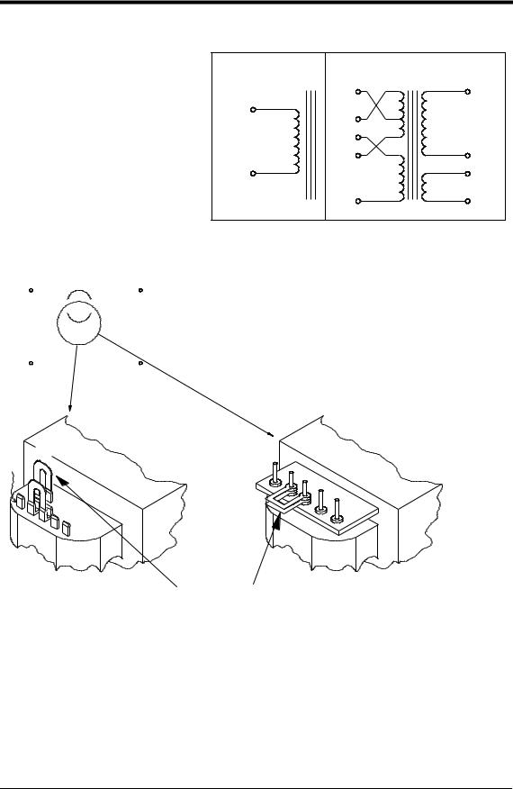
1.6. CHANGING TRANSFORMER TAPS
Before you wire ac power to the AT10.1, check the wiring of the main transformer T1, to be sure it is connected for your ac input voltage. The AT10.1 accepts standard input voltages of 120, 208 or 240 Vac by changing jumpers on T1. No other changes are required. The AT10.1 is wired at the factory for 240 Vac, except on special order. Models for 220, 380 or 416 Vac at 50/60 Hz are available on special order.
EXCEPTION: An AT10.1 battery charger rated for 480 Vac input uses a special transformer that has no taps or jumpers. The 480 Vac transformer cannot be used for any other input voltage.
Before changing the T1 taps, be sure that ac and dc supplies to the AT10.1 are turned off and locked out. Verify that no voltage is present by using a voltmeter at terminals TB1-L1 and TB1-L2 (ac), TB1(+) and TB1(-) (dc) and remote sense terminals (dc). Note that turning off the ac and dc circuit breakers on the AT10.1 does not eliminate live voltages inside the enclosure. Also de-energize any external wiring to the alarm relay contacts.
Verify that all voltages within the enclosure are de-energized and locked out. See section 3.5 for necessary steps to follow when accessing internal components within the AT10.1. Change the jumpers on T1 as shown in the table on the next page. All transformers have (2) jumpers; always use both as specified in the table. The transformers used in the small enclosure (586) use piggyback quick-connect terminals. The transformers in the larger enclosure (594) use 10-32 stud terminals.
Models designed for 220 Vac, 50/60 Hz have no jumpers, and can be used only for that voltage. Models designed for 380 or 416 Vac also have no jumpers, and can be operated on either voltage.
NOTE: This procedure refers only to Group I AT10.1 battery chargers (rated 6-25 Adc). A different procedure exists for Group II AT10.1 battery chargers (rated 30-100 Adc). Please refer to the Operating and Service Instructions specific to the Group II AT10.1 battery charger for changing the transformer taps on these larger units. Otherwise, damage to your charger and equipment may occur.
10
INSTALLING THE AT10.1
CHANGING TRANSFORMER TAPS - GRAPHICS
T1 CONNECTION TABLE
INPUT VAC |
|
|
|
JUMPERS |
|||||||||||
|
|
|
|
|
|
|
|
||||||||
120 |
|
|
|
|
H1-H3, H2-H5 |
||||||||||
208 |
|
|
|
|
H2-H4 (2) JUMPERS |
||||||||||
240 |
|
|
|
|
H2-H3 (2) JUMPERS |
||||||||||
480 |
|
|
|
|
NONE |
||||||||||
|
|
|
|
|
|
|
|
|
|
|
|
|
|
|
|
|
|
|
|
|
|
|
|
|
|
|
|
|
|
|
|
|
|
|
|
|
|
|
|
|
|
|
|
|
|
|
|
|
|
|
|
|
|
|
|
|
|
|
|
|
|
|
|
|
|
|
|
|
|
|
|
|
|
|
|
|
|
|
|
|
|
|
|
|
|
|
|
|
|
|
|
|
|
|
|
|
|
|
|
|
|
|
|
|
|
|
|
|
|
|
|
|
|
|
|
|
|
|
|
|
|
|
|
|
|
|
|
|
|
|
|
|
|
|
|
|
|
|
|
|
|
|
|
|
|
|
|
|
|
|
|
|
|
|
|
|
|
|
|
|
|
|
|
|
|
|
|
|
|
|
|
|
|
|
|
TYPICAL FOR TRANSFORMER
IN 586 ENCLOSURE
H1
H3
H2
H5
H4
480 V |
120/208/240 V |
|
PRIMARY |
PRIMARY |
SECONDARY |
|
H4 |
X1 |
H5 |
H5 |
|
|
|
|
|
H2 |
|
|
H3 |
X4 |
H1 |
|
Y2 |
|
H1 |
Y1 |
TRANSFORMER SCHEMATIC
PROCEDURE:
1)BE SURE ALL VOLTAGES ARE DE-ENERGIZED AND LOCKED OUT.
2)BE SURE TERMINALS ARE FULLY SEATED (586 ENCL).
.
3)BE SURE STUD TERMINALS ARE TIGHT (594 ENCL).
4)CHECK YOUR WORK AFTER COMPLETION.
5)FOR ADDITIONAL INFORMATION, SEE WIRING DIAGRAM IN APPENDIX.
TYPICAL FOR TRANSFORMER
IN 594 ENCLOSURE
H1 |
H3 |
H2
H5
H4
JUMPERS (2)
F1-5R2
11

INSTALLING THE AT10.1
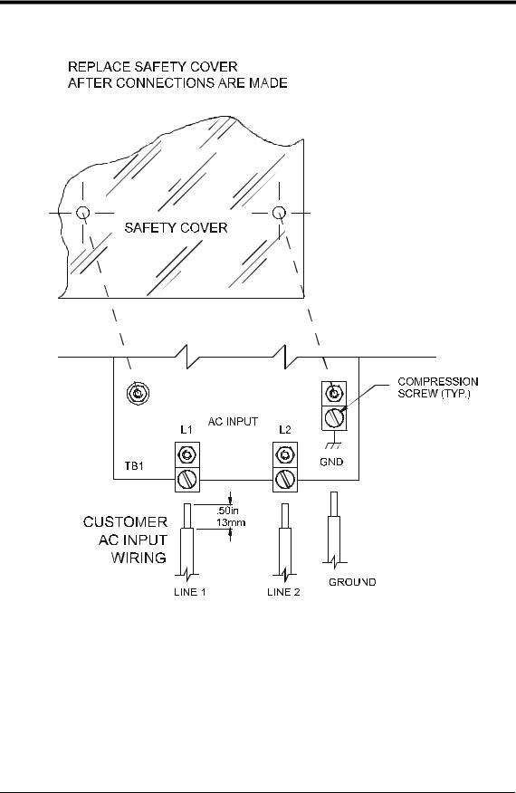
1.7. MAKING THE AC INPUT CONNECTIONS
Follow these steps to connect ac power to the AT10.1:
1.Use a branch circuit breaker or fused disconnect switch, properly sized for the maximum input current of the AT10.1, as shown in the table below. This device should have lockout capability so that the ac input can be deenergized and locked out for maintenance. A time delay circuit breaker or slow-blow fuse is recommended.
2.Size the ac input wiring per the National Electric Code (NEC) and local codes for the rating of the branch circuit breaker or fused disconnect switch.
3.All specific requirements of your facility take precedence over these instructions.
4.Be sure the AT10.1 main transformer, T1, is properly connected for your ac input voltage. See section 1.6 for details.
5.Remove the safety cover.
6.Run the ac wiring to terminals TB1-L1, TB1-L2 and TB1-GND on the I/O panel in the enclosure. Compression lugs accepting wire sizes #14-6 AWG. wire are supplied for your convenience. To make these connections, strip the insulation .50in / 13mm on the incoming wires and connect the wires to the appropriate lugs as shown on the next page.
7.Using a flat-head screwdriver, securely tighten the compression screws on the lugs to 35-45 in-lb / 4.0-5.1 Nm.
8.Reinstall the safety cover after you have made and checked all connections.
MAXIMUM INPUT CURRENT AT 120 Vac1
OUTPUT |
|
OUTPUT VOLTAGE |
|||||||
CURRENT |
12 |
|
|
24 |
|
48 |
|
130 |
|
|
|
|
|
||||||
|
|
|
|
|
|
|
|
|
|
6 |
2 |
|
|
4 |
|
8 |
|
14 |
|
|
|
|
|
|
|
|
|
|
|
12 |
3 |
|
|
7 |
|
14 |
|
30 |
|
16 |
4 |
|
|
9 |
|
18 |
|
32 |
|
|
|
|
|
|
|
|
|
|
|
20 |
5 |
|
|
11 |
|
23 |
|
39 |
|
|
|
|
|
|
|
|
|
|
|
25 |
6 |
|
|
14 |
|
29 |
|
49 |
|
|
|
|
|
|
|
|
|
|
|
Example (shaded):
A 130 Vdc/12 Adc battery charger draws 30 Aac at 120 Vac.
All currents shown are ±10%.
1 To determine the input current, Iac, for other input voltages, use the formula:
I ac |
= I T |
× |
120 |
|
V ac |
||||
|
|
|
where Vac is the new input voltage, and IT is the input current from the table above.
12
INSTALLING THE AT10.1
MAKING THE AC INPUT CONNECTIONS - GRAPHICS
NOTES:
1.The drawing above does not show other components mounted to the I/O panel. Be careful not to disconect any other component leads.
2.Always use a proper ground.
3.On 120 Vac input, connect the neutral leg to the terminal L2.
4.Wire insulation must be rated for 194° F / 90° C or better.
5.Use copper or aluminum conductors only.
13

INSTALLING THE AT10.1
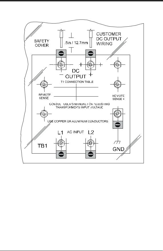
1.8. MAKING THE DC OUTPUT CONNECTIONS
Follow these steps to connect the battery to the AT10.1:
1.Size the dc wiring to minimize voltage drop. The acceptable wire size depends on your installation. As a guideline, the voltage drop should not exceed 1% of nominal output voltage at full current. Refer to the table below to determine the voltage drops for various wire sizes, currents and distances.
WIRE SIZING CHART
VOLTAGE DROP PER 100ft / 30.5m OF WIRE (FOR COPPER AT 68° F / 20° C)
WIRE SIZE |
|
DC CURRENT (AMPERES) |
|
||
(AWG.) |
|
|
|
|
|
6 |
12 |
16 |
20 |
25 |
|
|
|
|
|
|
|
16 |
2.5V |
5.0V |
6.7V |
8.2V |
10.5V |
|
|
|
|
|
|
14 |
1.6V |
3.2V |
4.2V |
5.3V |
6.6V |
|
|
|
|
|
|
12 |
1.0V |
2.0V |
2.6V |
3.3V |
4.2V |
|
|
|
|
|
|
10 |
0.63V |
1.3V |
1.7V |
2.1V |
2.6V |
|
|
|
|
|
|
8 |
0.40V |
0.80V |
1.1V |
1.3V |
1.7V |
|
|
|
|
|
|
6 |
0.25V |
0.50V |
0.66V |
0.83V |
1.1V |
|
|
|
|
|
|
4 |
0.16V |
0.32V |
0.42V |
0.52V |
0.65V |
|
|
|
|
|
|
EXAMPLE: 100ft / 30.5m of #8 AWG. wire at 16A has a 1.1V drop.
2.All specific requirements of your facility take precedence over these instructions.
3.The AT10.1 is factory wired to regulate output voltage at the output terminals. If the total voltage drop is greater than 1% (e.g., 1.3V for a 130 Vdc system), remote sense wiring is recommended, see section 1.9.
PROCEDURE
1.Use a dc disconnect switch or circuit breaker between the AT10.1 and dc bus. This device should have lockout capability to allow the AT10.1 to be disconnected from the dc bus for maintenance.
2.Remove the safety cover.
3.Run the dc wiring to terminals TB1(+) and TB1(-) on the I/O panel in the enclosure. Compression lugs, accepting wire sizes #14-6 AWG., are supplied for your convenience. To make these connections, strip the insulation .50in / 12.7mm on the incoming wires. Connect the wires to the appropriate lugs as shown on the next page.
4.Using a flat-head screwdriver, securely tighten the compression screws on the lugs to 35-45 in-lb / 4.0-5.1 Nm.
5.Reinstall the safety cover after you have made and checked all connections.
14
INSTALLING THE AT10.1
MAKING THE DC OUTPUT CONNECTIONS - GRAPHICS
NOTES:
1.The drawing above does not show other components mounted to the I/O panel. Be careful not to disconect any other component leads.
2.Always use a proper ground.
3.Wire insulation must be rated for 194° F / 90° C or better.
4.Use copper or aluminum conductors only.
15

INSTALLING THE AT10.1
1.9. WIRING THE AT10.1 FOR REMOTE SENSING
You can wire the AT10.1 to regulate the output voltage at the battery terminals, instead of at the charger output terminals. Remote sensing does the following:
1.Compensates for voltage drop in the dc wiring between the AT10.1 and the battery.
2.Directly monitors the battery or dc bus voltage. The front panel meter displays the actual voltage on the dc bus.
You wire the AT10.1 for remote sensing by installing a two-wire cable from the AT10.1 remote sense terminals to the battery terminals. The AT10.1 control circuitry then measures the dc voltage at the battery terminals, and controls the output of the charger to maintain the battery voltage at the desired float or equalize voltage.
NOTE: If the remote sense wiring fails, the AT10.1 detects the fault, and displays E 06 on the front panel meter. See section 3.2 for details.
CAUTION: The AT10.1 cannot protect against short circuits in the remote sense wiring. You should install a 1.0A fuse at the battery or dc bus end of the remote sense cable.
To wire the AT10.1 for remote sensing, follow the procedure and diagram on the next page.
If you ever need to disable remote sense, follow the steps below:
∙De-energize and lock out all ac and dc voltages to the AT10.1. Check with a voltmeter.
∙Disconnect the remote sense wires from the battery or dc bus terminals first.
CAUTION: You must do the steps above first.
∙Remove the remote sense leads from the remote sense (+) and (-) terminals on the I/O panel. Insulate each lead separately. Coil up the wires and leave them in the bottom of the charger, in case you want to wire for remote sense again in the future.
∙Reconnect wire # 74 to the dc output (+) terminal.
∙Reconnect wire # 72 to the dc output (-) terminal.
∙Restart the AT10.1 according to the instructions in section 2.1.
16
INSTALLING THE AT10.1
PROCEDURE
1.De-energize and lock out all ac and dc voltages within the AT10.1 enclosure. Check with a voltmeter.
2.Remove safety shield.
3.Wire the AT10.1 remote sense to the dc bus as shown in the figure below.
4.Move wires # 72 and # 74 from the TB1 (-) and (+) dc output terminals to the corresponding remote sense terminals as shown in the lower left figure.
5.Connect the external remote sense leads from the battery or dc bus to the remote sense terminals on the I/O panel as shown in the lower right figure.
6.Check your work thoroughly. Replace the safety shield before reeneregizing the charger.
7.Restart the AT10.1 according to the instructions in section 2.1.
NOTES:
1.Use #16 AWG. twisted pair.
2.Maximum current is 150 mA.
3.Run leads in their own conduit.
4.Fuse the wiring at the battery or dc bus.
17
INSTALLING THE AT10.1
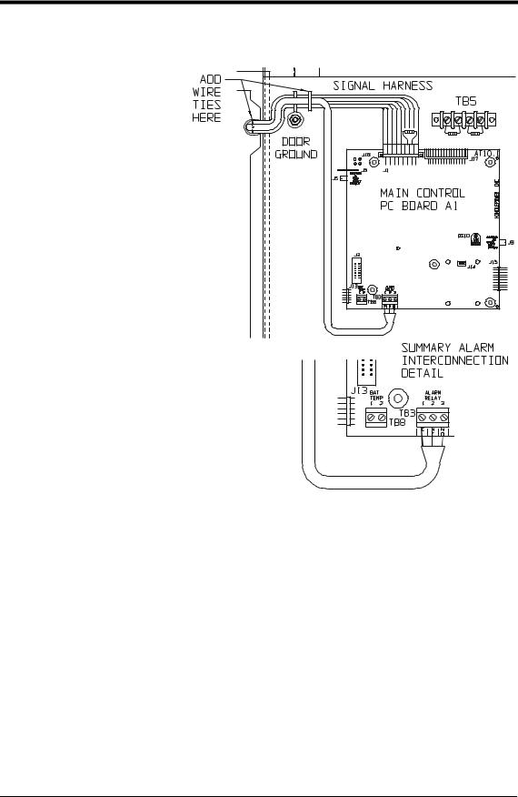
1.10.WIRING TO THE REMOTE ALARM CONTACTS
Built-in common alarm relay
The Primary Alarm functions are included as standard equipment with the AT10.1. The Common Alarm relay, located on the main control circuit board on the back of the door, provides one form C summary alarm (common alarm) contact that transfers for any alarm. Follow the procedure below to wire a remote annunciator to this contact. See section 2.2.7 for a description of the alarm functions.
PROCEDURE
1.Allow 30in / 762mm of wire inside the enclosure (excess will be trimmed).
2.Route wires to front door by following the existing harness through the door hinge as shown. Use (2) wire ties and allow a 4-6in / 102-153mm loop for the hinge.
3.Trim wires to the proper length for connecting to TB3. Strip .25in / 6.4mm of insulation from the wires. Make the connections at TB3, and securely tighten the screws.
NOTES:
1.Alarm contacts are rated at 0.5A / 125 Vac or Vdc.
2.Terminal block is a compression type, accepting wire sizes #22-14 AWG.
3.Terminals are labeled in non-alarm condition.
18
INSTALLING THE AT10.1
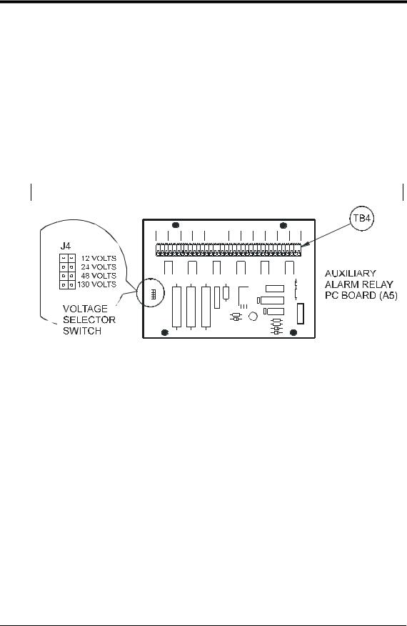
Auxiliary Relay Board (optional)
The Auxiliary Alarm Relay PC Board (A5), mounted inside the separate top enclosure (penthouse), provides two form C contacts (TB4-1 through TB4-36) for each of the following individual alarms:
∙High DC Voltage
∙Low DC Voltage
∙DC Output Failure
∙AC Failure
∙Ground Fault Detection (positive or negative)
∙Summary Alarm
|
|
|
|
|
|
|
|
|
|
DC OUT |
DC OUT |
|
|
GROUND |
GROUND |
|
|
HVDC |
HVDC |
LVDC |
LVDC |
FAILURE |
FAILURE |
AC FAIL |
AC FAIL |
DETECT |
DETECT |
SUMMARY |
SUMMARY |
||||||
C, NC, NO |
C, NC, NO |
C, NC, NO |
C, NC, NO |
C, NC, NO |
C, NC, NO |
C, NC, NO |
C, NC, NO |
C, NC, NO |
C, NC, NO |
C, NC, NO |
C, NC, NO |
||||||
1 |
2 |
3 |
4 |
5 |
6 |
7 |
8 |
9 |
10 11 12 |
13 14 15 |
16 17 18 |
19 20 21 |
22 23 24 |
25 26 27 |
28 29 30 |
31 32 33 |
34 35 36 |
Follow the procedure below to wire annunciators to one or more of these alarm contacts.
PROCEDURE
1.Remove the top panel from the penthouse enclosure (on top of the main charger enclosure).
2.Route your remote annunciator wiring into the penthouse enclosure through one of the unused knockouts in the side of the enclosure.
3.Connect the wiring (use #22-14 AWG.) to the appropriate terminals of TB4 on the back wall of the penthouse enclosure (as shown in the drawing at the right). Strip each wire .25in / 6.4mm, and securely tighten the terminal screws. The terminals are labeled in the non-alarm condition.
4.Replace the top panel on the penthouse enclosure.
NOTES:
1.Alarm contacts are rated at 0.5A / 125 Vac or Vdc.
2.Terminal block is a compression type, accepting wire sizes #22-14 AWG.
3.Terminals are labeled in non-alarm condition.
19

INSTALLING THE AT10.1
1.11.INSTALLING TEMP. COMPENSATION ASSEMBLY (OPTIONAL)
The temperature compensation assembly consists of a probe containing a temperature-dependent resistor in an epoxy module that you install near your battery. There are three steps in installing the assembly:
1.Mounting the probe assembly near the battery.
2.Installing an interconnection cable from the probe assembly to the AT10.1.
3.Wiring the charger end of the cable to a terminal block on the main control circuit board.
The actual tempco probe is the same for all battery types and all output voltages of the AT10.1. The kit part numbers differ depending on cable length ordered. See the tables in Appendix B on page 71 for ordering information. Each kit contains detailed installation instructions (JA501500). The main elements of the installation are outlined below.
WARNING:
High voltages appear at several points inside the battery charger. Use extreme caution when working inside the charger. Do not attempt to work inside the charger unless you are a qualified technician or electrician.
Disconnect and lock out all power to the battery charger before starting to remove or replace any components. Turn the ac power off at the distribution panel upstream from the battery charger. Disconnect the battery from the charger output terminals.
1.De-energize and lock out all ac and dc voltage sources to the AT10.1. Check with a voltmeter before proceeding.
2.Mount the probe on a clean, dry surface as close to the battery as possible, such as the battery rack. Do not mount the probe:
∙on the battery itself
∙on unpainted wood or bare galvanized metal.
∙on plastic surfaces
3.To apply the probe, clean the mounting surface with isopropyl alcohol, and allow to dry thoroughly. Remove the protective backing from the doublefaced adhesive tape on the probe, and securely press it onto the surface.
4.Install the cable supplied with the temperature compensation probe kit:
∙Start at the AT10.1. The end of the cable with two stripped wires and one lead with a quick-connect terminal will be connected inside the enclosure. Leave 30in / 762mm of cable inside the enclosure, and route the other end to the probe at the battery.
20
INSTALLING THE AT10.1
∙Run the cable though a conduit if possible, but not through a conduit containing any power wiring.
∙Route the other end to the probe at the battery and coil up excess cable.
NOTE: If the standard (25ft / 7.6m) cable isn't long enough, longer cable assemblies are available in lengths of 50, 100 & 200ft / 15.2, 30.5 & 61.0m. See Appendix B on page 71 for ordering information.
∙Be sure your wiring conforms to the NEC and your facility requirements.
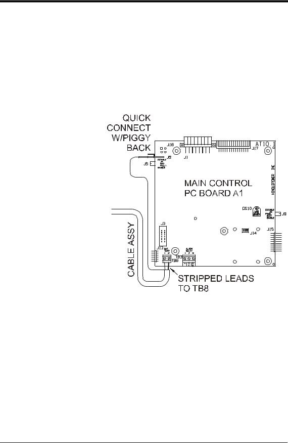
5.Attach the interconnection cable to the AT10.1 as shown in the figure below:
∙Route the cable within
the AT10.1 enclosure so that it runs with the wire harness to the back of the front panel, and easily reaches the main control circuit board.
∙ At the main control circuit board, insert one of the bare wires from the cable into each terminal of TB8. Polarity is not important.
∙Unplug the harness ground wire # 30 from terminal J6 on the left edge of the main control circuit board. Plug the connector at the end of the nylon-shielded wire of the cable assembly onto J6. Reconnect the ground wire # 30 from the system harness onto the piggy-back connector featured at the end of the nylon-shielded wire.
∙Using plastic wire ties, tie the interconnection cable loosely to the existing wire harness. Be especially sure that the cable conforms to the service loop at the hinge end of the door.
6.At the battery, connect the quick-connect terminals to the temperature compensation probe. Polarity is not important. Coil up any excess wire and tape or tie it together to prevent damage.
21

INSTALLING THE AT10.1
7.Check your work. Be sure that:
∙All connections are secure.
∙The shield is connected to ground at the charger end only (on the main circuit board).
∙The cable is connected to TB8 on the circuit board. Other terminal blocks may look similar.
8.Restart the AT10.1 using the startup procedure in section 2.1. During startup, the AT10.1 displays LEAD on the front panel, indicating that the temperature compensation is set up for lead-acid batteries. While this is being displayed, you can press any front panel key to change the display to read NICD, to change the temperature compensation setup for nickel cadmium batteries. The choice you make is saved internally, and will be used again by the AT10.1 the next time it starts.
9.Adjust the output float and equalize voltages to the battery manufacturer's recommended values, using the AT10.1's front panel meter, as described in section 2.3.2.
NOTE: If the temperature compensation probe, or the wiring from the probe to the AT10.1, is damaged and becomes an open circuit, the AT10.1 detects the damage and displays
E 08 on the display. The charger then reverts to normal non- temperature-compensated operation until the probe or wiring is repaired. Once the probe is repaired, you must restart the AT10.1 to activate the probe, as described in section 2.1.
Using temperature compensation
Whenever an electric storage battery is being charged, the terminal voltage of the battery changes a small amount whenever the battery temperature changes. As the battery temperature increases, its terminal voltage decreases. When the battery is being charged with a float type charger, with a constant output voltage, the float current increases when the temperature increases. This results in overcharging the battery, which can result in damage to the materials, or at least the need for more frequent maintenance.
When the AT10.1 is equipped with a temperature compensation probe, it is able to adjust the output voltage applied to the battery to keep the float current constant, thereby avoiding overcharging. The probe senses the ambient temperature at the battery, and adjusts the output float/equalize voltages to compensate for variations in temperature. If the ambient temperature increases, the AT10.1 output voltage decreases.
22

INSTALLING THE AT10.1
Please note the following:
∙You should set the Float and Equalize voltages to the values recommended by your battery manufacturer for 77° F (25° C).
∙When you enter the Edit mode to adjust the Float or Equalize voltage (see section 2.3.2), the front panel meter shows the 77° F (25° C) value for the Float or Equalize voltage, even if the battery is warmer or cooler than 77° F (25° C).
∙The actual output voltage of the AT10.1 may be different from the value shown on the front panel meter, if the battery is warmer or cooler than 77° F (25° C).
∙Use a digital meter to measure the actual output voltage of the AT10.1. If you know the temperature at the temperature compensation probe, you can use the graph below to determine that the output voltage is correct.
∙If the battery temperature goes below 32° F (0° C), there will be no further increase in charger output voltage. Likewise, if the battery temperature goes above 122° F (50° C), there is no further decrease in output voltage.
|
|
|
O U T P U T V O L T A G E V S B A T T E R Y T E M P E R A T U R E |
|
||
|
1 0 8 |
|
|
|
|
|
|
1 0 6 |
|
|
Lead-Acid |
|
|
|
1 0 4 |
|
|
|
|
|
Voltage |
1 0 2 |
|
|
|
|
|
Output |
|
|
|
|
|
|
|
N ickel-Cadm ium |
|
|
|
|
|
1 0 0 |
|
|
|
|
E x a m p le: |
|
Percent |
|
|
|
|
||
|
|
|
|
|
||
|
|
|
|
|
100 Deg . F |
|
|
|
|
|
|
9 7 % O u t p u t |
|
|
9 8 |
|
|
|
|
|
|
|
|
|
|
V o ltage |
|
|
9 6 |
|
|
|
|
|
|
9 4 |
|
|
|
|
|
|
2 0 |
4 0 |
6 0 |
8 0 |
1 0 0 |
120 |
Temperature, Degrees Fahrenheit
EXAMPLE: Suppose you have a lead-acid battery whose temperature is 100° F / 37.8° C. As shown on the graph, the output voltage should be approximately 97% of the 77° F voltage. If the float voltage is set on the front panel to 132 Vdc, the actual output voltage will be:
132 x 0.97 = 128 Vdc
23

OPERATING THE AT10.1
2. OPERATING THE AT10.1 BATTERY CHARGER
2.1. STARTING THE AT10.1
2.1.1.Understanding the startup sequence
The AT10.1 is set up at the factory to work with most common batteries and loads without further adjustment. When you start the AT10.1 for the first time, the factory settings (float voltage, equalize voltage, etc.) control the operation of the charger. You can change the settings after you start the charger. The FACTORY SETTINGS are shown in table on page 25.
The AT10.1 startup routine takes about five seconds. The microprocessor that controls the AT10.1 initializes the charger by reading the settings that are stored internally. The control circuit then "soft starts" the charger, and the dc output voltage and current increase gradually to the rated value.
2.1.2.Checking the installation
Be sure that you have followed the installation instructions carefully. Check the ac input supply voltage and the battery voltage, and be sure that they match the information on the AT10.1 nameplate. Verify that the jumpers on the main transformer T1 are correct for your ac supply voltage. Open the front panel, and check the battery polarity at the TB1 (+) and (-) terminals.
2.1.3.Starting the AT10.1
When you are sure that all connections to the AT10.1 are properly made, follow these steps to start up the AT10.1:
Using the Digital Meter
When you first start the AT10.1, the meter display alternates between dc output voltage and dc output current. Each reading is held for two seconds; lights to the left of the display indicate whether the meter is displaying voltage or current.
If you want to “freeze” the meter to display only voltage, press the METER MODE key on the front panel. To freeze the meter to display only current, press the key again. Press the key twice more to revert to the alternating display.
∙Turn on the front panel dc circuit breaker. The digital meter indicates the battery voltage only. If the meter display doesn't light, do not proceed. Turn off the dc breaker, and check all connections and the battery polarity again. Also check the battery voltage. It must be above 50% of nominal voltage to turn on the display. If you can't find the problem, refer to the Troubleshooting Procedure in section 3.1 on page 44.
CAUTION: If you try to turn on the dc circuit breaker with the battery connected in reverse polarity, the circuit breaker will immediately trip. Do not try to close the dc breaker again, since this may damage the battery charger. Correct the battery polarity before proceeding.
24

OPERATING THE AT10.1
∙If you have an optional temperature compensation probe installed, the front panel displays LEAD during startup, indicating that the temperature compensation is set up for lead-acid batteries. While this is being displayed, you can press any front panel key to change the display to read NICD, to change the temperature compensation setup for nickel cadmium batteries. The choice you make is saved internally, and will be used again by the AT10.1 then next time it starts.
∙Turn on the front panel ac circuit breaker. The digital meter displays the output voltage and current. See Using the Digital Meter on page 24. You should hear a soft hum from the AT10.1 as the output current increases.
NOTE: If you turn on the ac breaker before the dc breaker, and you have a filtered model of the AT10.1, there is a possibility that the dc breaker will trip when you try to turn it on. This is caused by the filter capacitors discharging into the battery. To get around this problem, turn off the ac breaker. Restart the AT10.1 by turning on the dc breaker first.
∙The green FLOAT indicator lights. Press the CHRG MODE key on the front panel. The FLOAT indicator goes off, and the yellow EQLZ indicator lights. Press the CHRG MODE key again to return the charger to the float mode.
The table below shows the normal factory settings for float and equalize voltages, equalize time, current limit setting, and alarm settings. If your purchase order specified other float or equalize voltage settings, a tag attached to the front panel of the AT10.1 lists the actual voltage settings.
FACTORY SETTINGS FOR ALL PARAMETERS
|
|
|
|
Nominal Vdc |
|
|||||
Parameter |
12 |
|
|
24 |
|
|
48 |
|
|
130 |
|
|
|
||||||||
|
|
|
|
|
|
|
|
|
|
|
Float Voltage |
13 |
|
|
26 |
|
|
52 |
|
|
131 |
|
|
|
|
|
|
|
|
|
|
|
Equalize Voltage |
14 |
|
|
28 |
|
|
56 |
|
|
139 |
|
|
|
|
|
|
|
|
|
|
|
HVDC Alarm |
14.4 |
|
|
28.8 |
|
|
57.6 |
|
|
144 |
|
|
|
|
|
|
|
|
|
|
|
LVDC Alarm |
12 |
|
|
24 |
|
|
48 |
|
|
120 |
|
|
|
|
|
|
|
|
|
|
|
Equalize Time |
|
|
|
|
24 Hours |
|
||||
|
|
|
|
|
|
|||||
Equalize Method |
|
|
|
Manual Timer |
|
|||||
|
|
|
|
|||||||
Current Limit |
|
110% of nominal output current |
|
|||||||
|
|
|
|
|
|
|
||||
HVDC Shutdown |
|
|
|
|
Disabled |
|
||||
|
|
|
|
|
|
|
|
|
|
|
25
 Loading...