


 Loading...
Cisco 8500 Series Wireless Controller
Installation Guide
October 2012
Revised: March 2013
Americas Headquarters
Cisco Systems, Inc. 170 West Tasman Drive
San Jose, CA 95134-1706 USA http://www.cisco.com Tel: 408 526-4000
800 553-NETS (6387) Fax: 408 527-0883
THE SPECIFICATIONS AND INFORMATION REGARDING THE PRODUCTS IN THIS MANUAL ARE SUBJECT TO CHANGE WITHOUT NOTICE. ALL STATEMENTS, INFORMATION, AND RECOMMENDATIONS IN THIS MANUAL ARE BELIEVED TO BE ACCURATE BUT ARE PRESENTED WITHOUT WARRANTY OF ANY KIND, EXPRESS OR IMPLIED. USERS MUST TAKE FULL RESPONSIBILITY FOR THEIR APPLICATION OF ANY PRODUCTS.
THE SOFTWARE LICENSE AND LIMITED WARRANTY FOR THE ACCOMPANYING PRODUCT ARE SET FORTH IN THE INFORMATION PACKET THAT SHIPPED WITH THE PRODUCT AND ARE INCORPORATED HEREIN BY THIS REFERENCE. IF YOU ARE UNABLE TO LOCATE THE SOFTWARE LICENSE OR LIMITED WARRANTY, CONTACT YOUR CISCO REPRESENTATIVE FOR A COPY.
The following information is for FCC compliance of Class A devices: This equipment has been tested and found to comply with the limits for a Class A digital device, pursuant to part 15 of the FCC rules. These limits are designed to provide reasonable protection against harmful interference when the equipment is operated in a commercial environment. This equipment generates, uses, and can radiate radio-frequency energy and, if not installed and used in accordance with the instruction manual, may cause harmful interference to radio communications. Operation of this equipment in a residential area is likely to cause harmful interference, in which case users will be required to correct the interference at their own expense.
The following information is for FCC compliance of Class B devices: This equipment has been tested and found to comply with the limits for a Class B digital device, pursuant to part 15 of the FCC rules. These limits are designed to provide reasonable protection against harmful interference in a residential installation. This equipment generates, uses and can radiate radio frequency energy and, if not installed and used in accordance with the instructions, may cause harmful interference to radio communications.
However, there is no guarantee that interference will not occur in a particular installation. If the equipment causes interference to radio or television reception, which can be determined by turning the equipment off and on, users are encouraged to try to correct the interference by using one or more of the following measures:
•Reorient or relocate the receiving antenna.
•Increase the separation between the equipment and receiver.
•Connect the equipment into an outlet on a circuit different from that to which the receiver is connected.
•Consult the dealer or an experienced radio/TV technician for help.
Modifications to this product not authorized by Cisco could void the FCC approval and negate your authority to operate the product.
The Cisco implementation of TCP header compression is an adaptation of a program developed by the University of California, Berkeley (UCB) as part of UCB’s public domain version of the UNIX operating system. All rights reserved. Copyright © 1981, Regents of the University of California.
NOTWITHSTANDING ANY OTHER WARRANTY HEREIN, ALL DOCUMENT FILES AND SOFTWARE OF THESE SUPPLIERS ARE PROVIDED “AS IS” WITH ALL FAULTS. CISCO AND THE ABOVE-NAMED SUPPLIERS DISCLAIM ALL WARRANTIES, EXPRESSED OR IMPLIED, INCLUDING, WITHOUT LIMITATION, THOSE OF MERCHANTABILITY, FITNESS FOR A PARTICULAR PURPOSE AND NONINFRINGEMENT OR ARISING FROM A COURSE OF DEALING, USAGE, OR TRADE PRACTICE.
IN NO EVENT SHALL CISCO OR ITS SUPPLIERS BE LIABLE FOR ANY INDIRECT, SPECIAL, CONSEQUENTIAL, OR INCIDENTAL DAMAGES, INCLUDING, WITHOUT LIMITATION, LOST PROFITS OR LOSS OR DAMAGE TO DATA ARISING OUT OF THE USE OR INABILITY TO USE THIS MANUAL, EVEN IF CISCO OR ITS SUPPLIERS HAVE BEEN ADVISED OF THE POSSIBILITY OF SUCH DAMAGES.
CCVP, the Cisco logo, and Welcome to the Human Network are trademarks of Cisco Systems, Inc.; Changing the Way We Work, Live, Play, and Learn is a service mark of Cisco Systems, Inc.; and Access Registrar, Aironet, Catalyst, CCDA, CCDP, CCIE, CCIP, CCNA, CCNP, CCSP, Cisco, the Cisco Certified Internetwork Expert logo, Cisco IOS, Cisco Press, Cisco Systems, Cisco Systems Capital, the Cisco Systems logo, Cisco Unity, Enterprise/Solver, EtherChannel, EtherFast, EtherSwitch, Fast Step, Follow Me Browsing, FormShare, GigaDrive, HomeLink, Internet Quotient, IOS, iPhone, IP/TV, iQ Expertise, the iQ logo, iQ Net Readiness Scorecard, iQuick Study, LightStream, Linksys, MeetingPlace, MGX, Networkers, Networking Academy, Network Registrar, PIX, ProConnect, ScriptShare, SMARTnet, StackWise, The Fastest Way to Increase Your Internet Quotient, and TransPath are registered trademarks of Cisco Systems, Inc. and/or its affiliates in the United States and certain other countries.
All other trademarks mentioned in this document or Website are the property of their respective owners. The use of the word partner does not imply a partnership relationship between Cisco and any other company. (0711R)
Any Internet Protocol (IP) addresses and phone numbers used in this document are not intended to be actual addresses and phone numbers. Any examples, command display output, network topology diagrams, and other figures included in the document are shown for illustrative purposes only. Any use of actual IP addresses or phone numbers in illustrative content is unintentional and coincidental.
Cisco 8500 Series Wireless Controller Installation Guide
© 2012 Cisco Systems, Inc. All rights reserved.

C O N T E N T S
Cisco 8500 Series Wireless Controller Installation Guide 1-1
About this Guide |
1-1 |
|
|
|
|
Obtaining Related Documentation |
1-2 |
|
|||
Cisco 8500 Series Wireless Controller |
1-2 |
||||
What is in the Cisco 8500 Series Wireless Controller 1-3 |
|||||
Integrated Management Module |
1-3 |
||||
Light path diagnostics |
1-3 |
|
|
|
|
Compliance and Safety Information |
1-4 |
||||
FCC Safety Compliance Statement |
1-4 |
||||
General Warnings, Regulatory and Safety 1-4 |
|||||
Conventions |
1-4 |
|
|
|
|
Warnings 1-5 |
|
|
|
|
|
Regulatory and Safety |
1-5 |
|
|
|
|
Required Tools and Information |
1-5 |
|
|||
Required Hardware |
1-5 |
|
|
|
|
CLI Console Requirements |
1-6 |
|
|
||
System Configuration Parameters |
1-6 |
||||
Choosing a Physical Location for the Cisco 8500 Series Wireless Controller 1-7 |
|||||
General Precautions |
1-7 |
|
|
|
|
Laser Devices |
1-7 |
|
|
|
|
Space and Airflow Requirements |
1-8 |
||||
Temperature Requirements |
1-8 |
|
|||
Power Requirements |
1-9 |
|
|
|
|
Power Supplies on the Cisco 8500 Series Wireless Controller 1-9 |
|||||
Batteries |
1-9 |
|
|
|
|
Electrical Grounding Requirements |
1-10 |
||||
Rack Warnings |
1-10 |
|
|
|
|
Unpacking the Controller |
1-10 |
|
|
|
|
Package Contents 1-11 |
|
|
|
||
Mounting the Cisco 8500 Series Wireless Controller in a Rack 1-11
Installing the Controller Into the Rack Cabinet Using Universal Rack Mount Kit 1-11
Front Panel 1-18 |
|
Front Panel Components |
1-18 |
Operator Information Panel |
1-19 |
Cisco 8500 Series Wireless Controller Installation Guide
iii

Contents
Operator Information Panel Components |
1-20 |
|
|
|
||||||
Light Path Diagnostics Panel 1-20 |
|
|
|
|
|
|
||||
Light Path Diagnostics Panel Components |
1-21 |
|
|
|
||||||
Rear Panel 1-24 |
|
|
|
|
|
|
|
|
|
|
Rear Panel Components |
|
1-24 |
|
|
|
|
|
|
||
Power-supply LEDs |
|
1-27 |
|
|
|
|
|
|
||
Cisco 8500 Series Wireless Controller Power Features 1-29 |
|
|||||||||
Turning on the Cisco 8500 Series Wireless Controller |
1-30 |
|
||||||||
Turning off the Cisco 8500 Series Wireless Controller |
1-30 |
|
||||||||
Grounding the Chassis |
1-30 |
|
|
|
|
|
|
|
|
|
Preventing ESD Damage |
1-30 |
|
|
|
|
|
|
|
||
Replacing a Failed Hot-Swap Hard Disk Drive |
1-31 |
|
|
|
||||||
Replacing a Hot-Swap AC Power Supply |
1-32 |
|
|
|
|
|||||
Replacing a Hot-Swap -48 VDC Power Supply |
1-33 |
|
|
|
||||||
Safety Information |
1-37 |
|
|
|
|
|
|
|
||
Removing DC Power Supply from Controller |
1-39 |
|
|
|
|
|||||
Connecting the Cables |
1-40 |
|
|
|
|
|
|
|
|
|
Connecting and Using the CLI Console |
1-40 |
|
|
|
|
|
||||
Powering On the Controller |
1-41 |
|
|
|
|
|
|
|||
Connecting the AC Version of the 8500 [AIR-CT8510-K9] to a Power Source |
1-41 |
|||||||||
Connecting the DC Version of the 8500 [AIR-CT85DC-K9] to a Power Source |
1-41 |
|||||||||
Running the Bootup Script and Power-On Self Test |
1-41 |
|
|
|||||||
Using the Startup Wizard |
1-43 |
|
|
|
|
|
|
|||
Logging into the Controller |
1-47 |
|
|
|
|
|
|
|||
Verifying Interface Settings and Port Operation |
1-47 |
|
|
|||||||
Connecting the Network (Distribution System) |
1-49 |
|
|
|
||||||
Connecting the Controller’s Service Port (Optional) |
1-49 |
|
|
|||||||
Connecting Access Points |
1-49 |
|
|
|
|
|
|
|||
Controller Specifications |
1-50 |
|
|
|
|
|
|
|||
Cisco 90-Day Limited Hardware Warranty Terms |
1-50 |
|
|
|
||||||
Safety Considerations and |
|
|
|
|
|
|
|
|
|
|
Translated Safety Warnings |
A-1 |
|
|
|
|
|
|
|||
Safety Considerations |
A-2 |
|
|
|
|
|
|
|
|
|
Warning Definition |
A-2 |
|
|
|
|
|
|
|
|
|
More Than One Power Supply |
A-5 |
|
|
|
|
|
|
|||
Installation Instructions |
A-7 |
|
|
|
|
|
|
|
|
|
Ground Conductor Warning |
A-9 |
|
|
|
|
|
|
|||
Cisco 8500 Series Wireless Controller Installation Guide
iv

Contents
Chassis Warning for Rack-Mounting and Servicing A-11 |
|||
Equipment Installation Warning |
A-20 |
||
Battery Handling |
A-23 |
|
|
Product Disposal |
A-25 |
|
|
Power Cable and AC Adapter |
A-27 |
||
Class 1 Laser Product |
A-28 |
|
|
Regulatory Information |
B-1 |
|
|
FCC Statement for Cisco 8500 Series Wireless Controller B-1 |
|||
Declaration of Conformity with Regard to the EU Directive 1999/5/EC (R&TTE Directive) B-1
Statement 191—VCCI Class A Warning for Japan B-2
Cisco 8500 Series Wireless Controller Installation Guide
v

Contents
Cisco 8500 Series Wireless Controller Installation Guide
vi

C H A P T E R 1
Cisco 8500 Series Wireless Controller
Installation Guide
About this Guide
This guide is designed to help you install and minimally configure your Cisco 8500 Series Wireless Controller. This document applies to the following products:
•AIR-CT8510-K9 - the AC version of the Cisco 8500 Series Wireless 8500 Controller
•AIR-CT85DC-K9 - the DC version of the Cisco 8500 Series Wireless 8500 Controller This document contains the following sections:
•Cisco 8500 Series Wireless Controller, page 1-2
•Obtaining Related Documentation, page 1-2
•What is in the Cisco 8500 Series Wireless Controller, page 1-3
•Compliance and Safety Information, page 1-4
•General Warnings, Regulatory and Safety, page 1-4
•Required Tools and Information, page 1-5
•Choosing a Physical Location for the Cisco 8500 Series Wireless Controller, page 1-7
•Unpacking the Controller, page 1-10
•Mounting the Cisco 8500 Series Wireless Controller in a Rack, page 1-11
•Front Panel, page 1-18
•Rear Panel, page 1-24
•Grounding the Chassis, page 1-30
•Preventing ESD Damage, page 1-30
•Replacing a Failed Hot-Swap Hard Disk Drive, page 1-31
•Replacing a Hot-Swap AC Power Supply, page 1-32
•Replacing a Hot-Swap -48 VDC Power Supply, page 1-33
•Removing DC Power Supply from Controller, page 1-39
•Connecting the Cables, page 1-40
•Connecting and Using the CLI Console, page 1-40
•Powering On the Controller, page 1-41
Cisco 8500 Series Wireless Controller Installation Guide
1-1

Chapter 1 Cisco 8500 Series Wireless Controller Installation Guide
Obtaining Related Documentation
•Using the Startup Wizard, page 1-43
•Controller Specifications, page 1-50
•Obtaining Documentation and Submitting a Service Request, page 1-50
•Cisco 90-Day Limited Hardware Warranty Terms, page 1-50
Obtaining Related Documentation
After installation and power up is complete, refer to the following documents for additional information on the Cisco 8500 Series Wireless Controller:
•For detailed software configuration information, refer to the appropriate controller configuration guide.
•For detailed feature support and compatibility information, refer to the latest release notes for the Cisco 8500 Series Wireless Controller.
These documents are available on Cisco.com. Follow these steps to access these documents:
Step 1 Browse to http://www.cisco.com.
Step 2 Click Support. A new window appears.
Step 3 Click Wireless under Find Product Support. The Select Your Product or Technology page appears.
Step 4 Enter Cisco 8500 in the Find field and click Find.
Step 5 Click the Cisco 8500 Series Wireless Controllers link. The Cisco 8500 Series Controllers Introduction page appears.
Step 6 Choose the appropriate link for the documentation you want to view or download.
Cisco 8500 Series Wireless Controller
The Cisco 8500 Series Wireless Controller is a highly scalable and flexible platform that enables mission-critical wireless networking in large-scale service provider and large-campus deployments.
The Cisco 8500 Series Wireless Controller can manage wireless access points in up to 6,000 branch locations and allows IT managers to configure, manage, and troubleshoot up to 6,000 access points and 64,000 clients from the data center. The Cisco 8500 Series Wireless Controller supports secure guest access, rogue detection for Payment Card Industry (PCI) compliance and in-branch (locally switched) Wi-Fi voice and video.
The 8500 series wireless controller can manage Centralized (local mode), FlexConnect mode, and mesh deployments in a single controller.
This Installation Guide contains information and instructions for setting up your Cisco 8500 Series Wireless Controller and instructions for cabling and configuring the controller. For diagnostics and troubleshooting information, see diagnostics and troubleshooting tables, Table 1-1 on page 1-22 and Table 1-2 on page 1-27.
Cisco 8500 Series Wireless Controller Installation Guide
1-2
Chapter 1 Cisco 8500 Series Wireless Controller Installation Guide
What is in the Cisco 8500 Series Wireless Controller
Note The Cisco 8500 Series Wireless Controller is available in two versions: the standard AC version with the PID [AIR-CT8510-K9] and the new DC version with the PID [AIR-CT85DC-K9]. The only difference between these two offerings is the power supply shipped with the product.
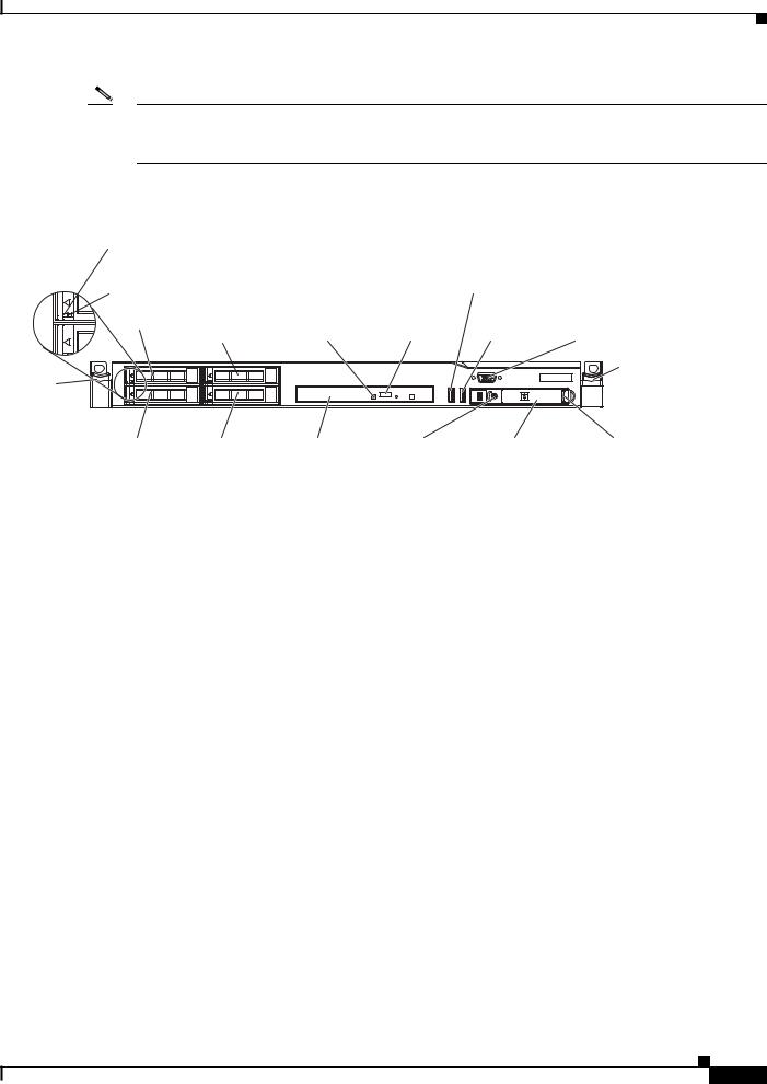
Figure 1-1 |
Cisco 8500 Series Wireless Controller |
|
|
|
||
|
Hard disk drive |
|
|
|
|
|
|
activity LED (green) |
|
|
|
|
|
|
Hard disk drive |
|
|
USB 1 |
|
|
|
|
|
connector |
|
||
|
status LED (amber) |
|
|
|
||
|
|
|
|
|
||
|
Drive bay 0 |
Drive bay 2 |
Optical drive |
Optical drive |
USB 2 |
Video |
|
|
(Not used) |
activity LED |
eject button |
connector |
connector |
Rack |
|
|
|
|
|
Rack |
release |
|
|
|
|
|
release |
latch |
|
|
|
|
|
latch |
|
Drive bay 1 |
Drive bay 3 |
Optical |
Power-control |
Operator |
Operator information |
|
|
(Not used) |
drive bay |
button and LED |
information panel release latch |
|
|
|
|
|
|
panel |
|
282299
What is in the Cisco 8500 Series Wireless Controller
The following sections describe the features and technologies used by the Cisco 8500 Series Wireless Controller.
Integrated Management Module
The Integrated Management Module (IMM) combines service processor functions. The IMM provides advanced service-processor control, monitoring, and alerting function. If an environmental condition exceeds a threshold or if a system component fails, the IMM lights LEDs to help you diagnose the problem, records the error in the event log, and alerts you to the problem. The IMM provides remote server management through the following industry-standard interfaces:
•Simple Network Management Protocol (SNMP) version 3
•Web browser
For additional information, see the Integrated Management Module User Guide.
Light path diagnostics
Light path diagnostics provides LEDs to help you diagnose problems. For more information about the light path diagnostics, see Light Path Diagnostics Panel, page 1-20.
Cisco 8500 Series Wireless Controller Installation Guide
1-3

Chapter 1 Cisco 8500 Series Wireless Controller Installation Guide
Compliance and Safety Information
Compliance and Safety Information
FCC Safety Compliance Statement
Modifying the equipment without Cisco’s authorization may result in the equipment no longer complying with FCC requirements for Class A digital devices. In that event, your right to use the equipment may be limited by FCC regulations, and you may be required to correct any interference to radio or television communications at your own expense.
This equipment has been tested and found to comply with the limits for a Class A digital device, pursuant to Part 15 of the FCC Rules. These limits are designed to provide reasonable protection against harmful interference when the equipment is operated in a commercial environment. This equipment generates, uses, and can radiate radio frequency energy and, if not installed and used in accordance with the instruction manual, may cause harmful interference to radio communications. Operation of this equipment in a residential area is likely to cause harmful interference in which case users will be required to correct the interference at their own expense.
Try to correct the interference by one or more of the following measures:
•Verify that the ambient temperature remains between 50 to 95° F (10 to 35° C), taking into account the elevated temperatures when installed in a rack or enclosed space.
•When multiple Cisco 8500 Series Wireless Controllers are mounted in an equipment rack, be sure that the power source is sufficiently rated to safely run all the equipment in the rack.
•Verify the integrity of the electrical ground before installing the controller.
General Warnings, Regulatory and Safety
Conventions
Safety warnings appear throughout this guide in procedures that may harm you if performed incorrectly. A warning symbol precedes each warning statement. Specific warnings are included in the sections to which they apply.
Warning This warning symbol means danger. You are in a situation that could cause bodily injury. Before you work on any equipment, be aware of the hazards involved with electrical circuitry and be familiar with standard practices for preventing accidents. Use the statement number provided at the end of each warning to locate its translation in the translated safety warnings that accompanied this device. Statement 1071 SAVE THESE INSTRUCTIONS
Caution Means reader be careful. In this situation, you might do something that could result in equipment damage or loss of data.
Cisco 8500 Series Wireless Controller Installation Guide
1-4
Chapter 1 Cisco 8500 Series Wireless Controller Installation Guide
Required Tools and Information
Warnings
The warnings below are general warnings that are applicable to the entire guide. Specific warnings are included in the sections to which they apply.
Warning There is the danger of explosion if the battery is replaced incorrectly. Replace the battery only with the same or equivalent type recommended by the manufacturer. Dispose of used batteries according to the manufacturer’s instructions. Statement 1015
Warning Read the installation instructions before connecting the system to the power source. Statement 1004
Warning Only trained and qualified personnel should be allowed to install, replace, or service this equipment. Statement 1030
Warning Ultimate disposal of this product should be handled according to all national laws and regulations. Statement 1040
Warning Class 1 laser product. Statement 1008
Regulatory and Safety
Note Refer to Appendix A for translated safety information for the Cisco 8500 Series Wireless Controller.
Note Refer to Appendix B for regulatory information for the Cisco 8500 Series Wireless Controller.
Required Tools and Information
This section lists the required hardware and other information that you need to install and setup the controller.
Required Hardware
You need the following equipment to install a Cisco 8500 Series Wireless Controller in an Electronics Industries Alliance (EIA) rack:
•A Cisco 8500 Series Wireless Controller
•Network cables
Cisco 8500 Series Wireless Controller Installation Guide
1-5
Chapter 1 Cisco 8500 Series Wireless Controller Installation Guide
Required Tools and Information
•One rack unit (RU) free space in an EIA-standard rack
•One or two Cisco SFP-10G-SR modules and corresponding optical cables
•Rack mounting kit (included with the Cisco 8500 Series Wireless Controller shipment)
•A serial console cable
For installing AIR-CT85DC-K9, the DC version of the Cisco Series 8500 Wireless Controller, 12 AWG copper cables and appropriate termination connectors are required. See details in Powering On the Controller, page 1-41.
Note If you are installing this unit in a threaded-hole rack, you must supply screws that fit the threaded-hole rack and the appropriate screwdriver or Torx driver for those screws.
CLI Console Requirements
You need this equipment to connect to the controller console:
• ANSI or VT-100 terminal emulator application on a laptop, desktop, or palmtop
Note Please refer to the latest Release Notes for Cisco 8500 Series Wireless Controller for compatibility by release between the Cisco WCS and controller releases at: http://www.cisco.com/en/US/products/ps12722/prod_release_notes_list.html
System Configuration Parameters
Obtain the following initial configuration parameters from your wireless LAN or network administrator:
•A system (controller) name.
•An administrative username and password.
•A service port interface IP address configuration protocol (none or DHCP).
•A management interface (DS port or network interface port) IP address.
Note The service port interface and management interface must be on different subnets.
•A management interface netmask address.
•A management interface default router IP address.
•A VLAN identifier if the management interface is assigned to a VLAN, or 0 for an untagged VLAN.
•Distribution system physical port number—1 through 2 for back panel 10 Gigabit Ethernet ports (with SFP+ 10G module).
•IP address of the default DHCP server that will supply IP addresses to clients.
•A virtual gateway IP address (a fictitious, unassigned IP address, such as 1.1.1.1, used by all Cisco wireless LAN controller Layer 3 security and mobility managers).
•A Cisco wireless LAN controller mobility group name, if required.
Cisco 8500 Series Wireless Controller Installation Guide
1-6

Chapter 1 Cisco 8500 Series Wireless Controller Installation Guide
Choosing a Physical Location for the Cisco 8500 Series Wireless Controller
•An 802.11 network name (SSID) for WLAN 1. This is the default SSID that the access points use when they join with the controller.
•Whether or not to allow static IP addresses from clients.
–Yes is more convenient, but has lower security (session can be hijacked).
–No is less convenient, but has higher security and works well for Windows XP devices.
•RADIUS server IP address, communications port, and secret (if you are configuring a RADIUS server).
•The country code for this installation. Refer to the Cisco Wireless LAN Controller Configuration Guide for country code information. This guide is available at cisco.com.
•Status of the 802.11a, 802.11b, and 802.11g networks (enabled or disabled).
•Status of radio resource management (RRM) (enabled or disabled).
•An IP address for the Integrated Management Module (IMM), if you are using a static IP address for IMM access. The IMM can use either a shared port with service port or the dedicated IMM Ethernet port.
Choosing a Physical Location for the Cisco 8500 Series Wireless Controller
For maximum safety and reliability, mount the controller using the following guidelines.
General Precautions
To reduce the risk of personal injury or damage to the controller:
•Place the product away from radiators, heat registers, stoves, amplifiers, or other products that produce heat.
•Never use the product in a wet location.
•Avoid inserting foreign objects through openings in the product.
•To reduce risk of injury from electric shock hazards, do not open the product enclosure.
Laser Devices
Laser devices are used within the DVD of the controller. The DVD has no defined use at the customer site.
To reduce the risk of exposure to hazardous radiation:
•Do not try to open the laser device enclosure. There are no user-serviceable components inside.
•Do not operate controls, make adjustments, or perform procedures to the laser device other than those specified herein.
•Allow only Cisco authorized service technicians to repair the laser device.
Cisco 8500 Series Wireless Controller Installation Guide
1-7
Chapter 1 Cisco 8500 Series Wireless Controller Installation Guide
Choosing a Physical Location for the Cisco 8500 Series Wireless Controller
Space and Airflow Requirements
Caution
Caution
Caution
Install the controller in a EIA-standard rack. One rack unit is required for each controller.
Ensure that you can reach the controller and all cables.
•Ensure that the controller is within 328 ft (100 m) equivalent distance from any equipment connected to the 10/100/1000BASE-T/10G ports. For specifications on the fiber optic cables, see “Connecting the Network (Distribution System)” section on page 1-49.
•Ensure that the power cord can reach a 110 or 220 VAC grounded electrical outlet.
Ensure that there is sufficient room at the back of the controller for all cables and connectors.
•Leave a minimum clearance of 63.5 cm (25 in.) in front of the rack.
•Leave a minimum clearance of 76.2 cm (30 in.) behind the rack.
•Leave a minimum clearance of 121.9 cm (48 in.) from the back of the rack to the back of another rack or row of racks.
To prevent improper cooling and damage to the equipment, do not block the ventilation openings.
Always use blanking panels to fill empty vertical spaces in the rack. This arrangement ensures proper airflow. Using a rack without blanking panels results in improper cooling that can lead to thermal damage.
When selecting a rack to use, observe the following additional requirements to ensure adequate airflow and to prevent damage to the equipment: (1) Front and rear doors—If the 42U rack includes closing front and rear doors, you must allow 5,350 sq. cm (830 sq. in.) of holes evenly distributed from top to bottom to permit adequate airflow (equivalent to the required 64 percent open area for ventilation).
(2) Side—The clearance between the installed rack component and the side panels of the rack must be a minimum of 7 cm (2.75 in.).
Temperature Requirements
To ensure continued safe and reliable equipment operation, install or position the system in a well ventilated, climate-controlled environment.
Ensure that the ambient operating temperature remains between 10 and 35° C (50 and 95° F), taking into account the elevated temperatures that occur when equipment is installed in a rack.
Caution To reduce the risk of damage to the equipment when installing third-party options: (1) Do not permit optional equipment to impede airflow around the controller or to increase the internal rack temperature beyond the maximum allowable limits. (2) Do not exceed the manufacturer’s maximum recommended ambient temperature (TMRA).
Cisco 8500 Series Wireless Controller Installation Guide
1-8
Chapter 1 Cisco 8500 Series Wireless Controller Installation Guide
Choosing a Physical Location for the Cisco 8500 Series Wireless Controller
Power Requirements
Installation of this equipment must comply with local and regional electrical regulations governing the installation of information technology equipment by licensed electricians. This equipment is designed to operate in installations covered by NFPA 70, 1999 Edition (National Electric Code) and NFPA 75, 1992 (code for Protection of Electronic Computer/Data Processing Equipment). For electrical power ratings on options, refer to the product rating label or the user documentation supplied with that option.
Caution Protect the controller from power fluctuations and temporary interruptions with a regulating uninterruptible power supply (UPS). This device protects the hardware from damage caused by power surges and voltage spikes and keeps the system in operation during a power failure.
When installing more than one controller, you may need to use additional power distribution devices (PDUs) to safely provide power to all devices. Observe the following guidelines:
•Balance the controller power load among available AC supply branch circuits.
•If you are using the AC version [AIR-CT8510-K9], do not allow the overall system AC current load to exceed 80 percent of the branch circuit AC current rating.
•Do not use common power outlet strips for this equipment.
•Provide a separate electrical circuit for the controller.
Please follow the instructions in Connecting the DC Version of the 8500 [AIR-CT85DC-K9] to a Power Source, page 1-41 to connect the DC version [AIR-CT85DC-K9] to DC power source.
Power Supplies on the Cisco 8500 Series Wireless Controller
The Cisco 8500 Series Wireless Controller has two power supplies.
Warning This unit might have more than one power supply connection. All connections must be removed to de-energize the unit. Statement 1028
Caution Verify that the external power source connected to the controller matches the type of power source indicated on the electrical ratings label. If you are not sure of the type of power source required, consult your Cisco authorized reseller or local power company.
Batteries
The controller might include a real-time clock battery or coin cell battery that might contain perchlorate and might require special handling when recycled or disposed of in California.
Refer to the following link for disposal information.
http://www.dtsc.ca.gov/hazardouswaste/perchlorate
Caution Do not dispose of batteries with the general household waste. Recycle them using the public collection system.
Cisco 8500 Series Wireless Controller Installation Guide
1-9
Chapter 1 Cisco 8500 Series Wireless Controller Installation Guide
Unpacking the Controller
Electrical Grounding Requirements
The controller must be grounded properly for proper operation and safety. In the United States, you must install the equipment in accordance with NFPA 70, 1999 Edition (National Electric Code), Article 250, as well as any local and regional building codes. In Canada, you must install the equipment in accordance with Canadian Standards Association, CSA C22.1, Canadian Electrical Code. In all other countries, you must install the equipment in accordance with any regional or national electrical wiring codes, such as the International Electrotechnical Commission (IEC) Code 364, parts 1 through 7.
Furthermore, you must verify that all power distribution devices used in the installation, such as branch wiring and receptacles, are listed or certified grounding-type devices. Because of the high ground-leakage currents associated with multiple systems connected to the same power source, Cisco recommends the use of a PDU that is either permanently wired to the building’s branch circuit or includes a nondetachable cord that is wired to an industrial-style plug. NEMA locking-style plugs or those complying with IEC 60309 are considered suitable for this purpose. Using common power outlet strips for the controller is not recommended.
Rack Warnings
Warning To prevent bodily injury when mounting or servicing this unit in a rack, you must take special precautions to ensure that the system remains stable. The following guidelines are provided to ensure your safety: (1) This unit should be mounted at the bottom of the rack if it is the only unit in the rack.
(2) When mounting this unit in a partially filled rack, load the rack from the bottom to the top with the heaviest component at the bottom of the rack. (3) If the rack is provided with stabilizing devices, install the stabilizers before mounting or servicing the unit in the rack. Statement 1006.
Caution To reduce the risk of personal injury or equipment damage when unloading a rack, at least two people are needed to safely unload the rack from the pallet.
Caution To prevent damage, ensure that water or excessive moisture cannot get into the controller.
Unpacking the Controller
Follow these steps to unpack the Cisco 8500 Series Wireless Controller and prepare it for operation:
Step 1 Open the shipping container and carefully remove the contents.
Step 2 Return all packing materials to the shipping container and save it.
Step 3 Ensure that all items listed in the “Package Contents” section on page 1-11 are included in the shipment.
Step 4 Check each item for damage. If any item is damaged or missing, notify your authorized Cisco sales representative.
Cisco 8500 Series Wireless Controller Installation Guide
1-10

Chapter 1 Cisco 8500 Series Wireless Controller Installation Guide
Mounting the Cisco 8500 Series Wireless Controller in a Rack
Package Contents
Each controller package contains the following items:
•Cisco 8500 Series Wireless Controller
•One rack mount kit
•Two power cords (for AIR-CT8510-K9 only)
•One console cable for 10 Gb SFP+ card
•Regulatory Compliance and Safety Information for the Cisco 8500 Series Wireless Controller
•Cisco product registration and Cisco documentation feedback cards
Mounting the Cisco 8500 Series Wireless Controller in a Rack
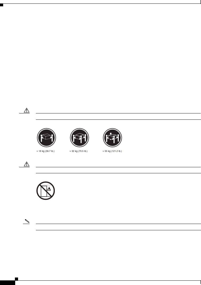
Warning Only trained and qualified personnel should be allowed to install, replace, or service this equipment. Statement 1030
Caution The controller is heavy (35 lbs, 15.9 kgs).
To reduce the risk of personal injury or damage to the equipment:
•Observe local occupational health and safety requirements and guidelines for manual material handling.
•Get help to lift and stabilize the controller during installation or removal is recommended, especially when the system is not fastened to the rails.
•Use caution when installing the controller in or removing it from the rack; it is unstable when not fastened to the rails.
•Always plan the rack installation so that the heaviest item is on the bottom of the rack. Install the heaviest item first and continue to populate the rack from the bottom to the top.
The controller comes with a universal rack mount kit that can be installed in a square-hole rack, round-hole rack, or a threaded-hole rack. You can order replacement universal rack mount kits from Cisco. The replacement part PID is AIR-SRVR-URMK=.
Note You must provide the threaded-hole screws to secure the mounting rails to the rack. Threaded-hole screws are not shipped with the system.
Installing the Controller Into the Rack Cabinet Using Universal Rack Mount Kit
Review the documentation that comes with the rack cabinet for safety and cabling information. Before you install the controller in a rack cabinet, review the following guidelines:
•Two or more people are required to install this device in a rack cabinet.
•Make sure that the room air temperature is below 35° C (95° F).
Cisco 8500 Series Wireless Controller Installation Guide
1-11
Chapter 1 Cisco 8500 Series Wireless Controller Installation Guide
Mounting the Cisco 8500 Series Wireless Controller in a Rack
•Do not block any air vents; usually 15 cm (6 in.) of space provides proper airflow.
•Do not leave open spaces above or below an installed controller in your rack cabinet. To help prevent damage to controller components, always install a blank filler panel to cover the open space and to help ensure proper air circulation.
•Install the controller only in a rack cabinet with perforated doors.
•Plan the device installation starting from the bottom of the rack cabinet.
•Install the heaviest device in the bottom of the rack cabinet.
•Do not extend more than one device out of the rack cabinet at the same time.
•Remove the rack doors and side panels to provide easier access during installation.
•Connect the controller to a properly grounded outlet.
•Do not overload the power outlet when you install multiple devices in the rack cabinet.
•Install the controller in a rack that meets the following requirement:
–Minimum depth of 70 mm (2.76 in.) between the front mounting flange and inside of the front door.
Caution Use safe practices when lifting.
Caution Do not place any object on top of rack-mounted devices.
The following illustration shows the items that you need to install the controller in the rack cabinet. If any items are missing or damaged, contact your place of purchase.
Note Some items come with the controller, not in the rack installation kit.
Cisco 8500 Series Wireless Controller Installation Guide
1-12

Chapter 1 Cisco 8500 Series Wireless Controller Installation Guide
Mounting the Cisco 8500 Series Wireless Controller in a Rack
Slide rail
(left) Slide rail (right)
EIA latches 


(2)
Cage bars
(4)
Front of rails |
|
Clip nuts |
|
|
(13) |
||
10-32 screws |
12-24 screws |
||
M6 screws |
|||
(13) |
(13) |
(12) |
255172
Note Use cage bars with square-holed racks, clip nuts with round-holed racks, and your own screws or the screws provided in this kit with threaded-hole racks.
Note If the slide rails in your rack installation kit came with shipping thumbscrews, remove them before you begin the following installation procedure.
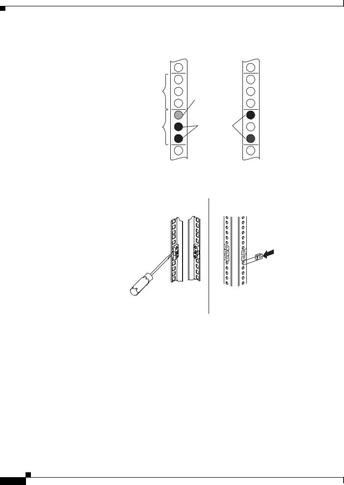
Step 1 Select an available 1U space in your rack to install your controller. If you have either a round-holed or square-holed rack, install cage bars or clip nuts in the middle and the bottom (optional for the upper) holes of the lower U on each side of the front of the rack. Then, install cage bars or clip nuts in the upper and the bottom holes of the lower U on each side of the rear of the rack.
Cisco 8500 Series Wireless Controller Installation Guide
1-13
Chapter 1 Cisco 8500 Series Wireless Controller Installation Guide
Mounting the Cisco 8500 Series Wireless Controller in a Rack
Front |
Rear |
Upper U
(For 2 U
system)
Lower U
Optional screw to secure system into the rack
Clip or cage nuts
255156
Step 2 Use a screwdriver to install the cage bars or the clip nuts on the inside of the mounting rail, as required for your rack, into the selected holes.
Front Rear |
Front Rear |
Cage |
Clip |
|
bars |
||
nuts |
||
|
255157
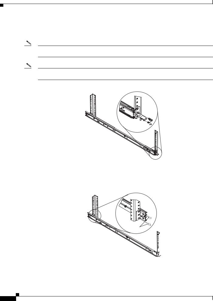
Step 3 The rail depth can be adjusted from 17 in (432 mm) to 31.25 in (794 mm). To adjust the depth, you can loosen the nuts on the posts and slide the bracket until the distance between the front and rear slide rail flanges matches the distance between the front and rear EIA rails of the rack cabinet. If you need further adjustment, remove the nuts, move the bracket to the appropriate set of posts (A, B, C, and D) to obtain the appropriate slide rail depth, then reinstall and tighten the nuts.
Cisco 8500 Series Wireless Controller Installation Guide
1-14
Chapter 1 Cisco 8500 Series Wireless Controller Installation Guide
Mounting the Cisco 8500 Series Wireless Controller in a Rack
Post D
Post C
Post B
Post A
Slots
255158
Step 4 To remove the support bracket, remove the screw (1) and remove the bracket (2) from the rear of the slide rail.
1
2
255160
Step 5 To remove the mounting brackets, remove the screws (1) and (3). Slide out the brackets (2) and (4) from the rear of the slide rail.
3
4
1
2 |
255161 |
|
Cisco 8500 Series Wireless Controller Installation Guide
1-15
Chapter 1 Cisco 8500 Series Wireless Controller Installation Guide
Mounting the Cisco 8500 Series Wireless Controller in a Rack
Step 6 Attach the front of the slide rail and EIA latch to the front of the rack cabinet by installing a screw in the bottom hole of the lower U; then, install another screw in the middle hole of the lower U to attach the front of the slide rail to the front of the rack cabinet.
Note When you fasten the slides to the rack, ensure the screws are engaged but the flange can move slightly. You will use a screwdriver to fully tighten them in Step 9.
Note Use 12-24 screws (not hex head M6 screws) on the front mounting bracket if you are installing this system into a rack with round or square holes (i.e., not threaded holes).
Cap head 

M6 screw
255170
Step 7 Use two screws to attach the rear of the slide rail to the rear of the rack cabinet in the upper and the bottom holes of the lower U.
Repeat Step 3 through Step 7 to install the other slide rail into the rack.
Hex head
M6 screw


 255171
Cisco 8500 Series Wireless Controller Installation Guide
1-16
Chapter 1 Cisco 8500 Series Wireless Controller Installation Guide
Mounting the Cisco 8500 Series Wireless Controller in a Rack
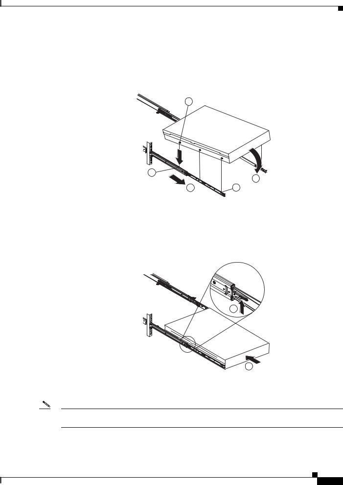
Step 8 Pull the slide rails forward (1) until they click, two times, into place. Carefully lift the controller and tilt it into position over the slide rails so that the rear nail heads (2) on the controller line up with the rear slots (3) on the slide rails. Slide the controller down until the rear nail heads slip into the two rear slots, and then slowly lower the front of the controller (4) until the other nail heads slip into the other slots on the slide rails. Make sure that the front latch (5) slides over the nail heads.
2
3
4
1  5
5
255162
Step 9 Lift the locking levers (1) on the slide rails and push the controller (2) all the way into the rack until it clicks into place.
Slide the system in and out twice to make sure the system slides correctly. Push the system inwards to the rack as close as possible but able to access the screws with a screwdriver. Then tighten the screws with a screwdriver.
1
2
255163
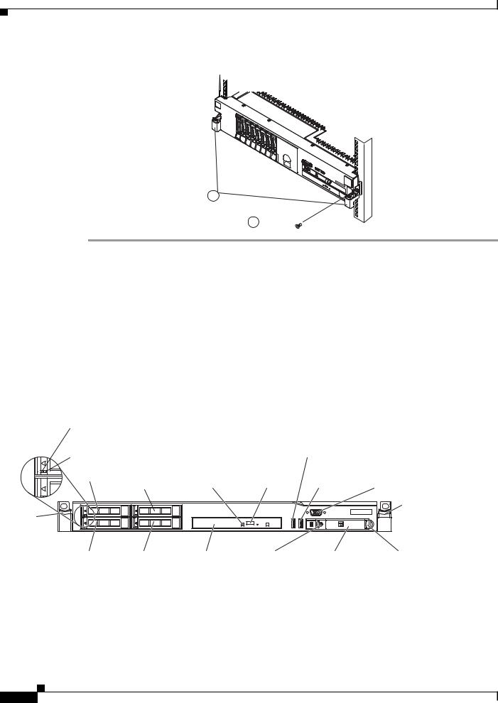
Step 10 Slide the controller into the rack until it snaps into place. To slide the controller out of the rack, press on the release latches (1).
Note When you move the rack cabinet, or if you install the rack cabinet in a vibration-prone area, insert the optional M6 screws (2) in the front of the controller.
Cisco 8500 Series Wireless Controller Installation Guide
1-17
Front Panel
1
Chapter 1 Cisco 8500 Series Wireless Controller Installation Guide
255169
2 

To remove the controller from the rack, reverse these instructions. Store this information with your controller documentation for future use.
Front Panel
Figure 1-2 shows the controls, Light Emitting Diodes (LEDs), and connectors on the front panel of the Cisco 8500 Series Wireless Controller.
Figure 1-3 shows a detailed view of the operator information panel.
Figure 1-2 Cisco 8500 Series Wireless Controller Front Panel
Hard disk drive |
|
|
activity LED (green) |
|
|
Hard disk drive |
|
|
status LED (amber) |
|
|
Drive bay 0 Drive bay 2 |
Optical drive |
Optical drive |
(Not used) |
activity LED |
eject button |
Rack |
|
|
release |
|
|
latch |
|
|
USB 1 connector
USB 2 |
Video |
connector |
connector |
Rack release latch
Drive bay 1 |
Drive bay 3 |
Optical |
Power-control |
Operator |
Operator information |
|
(Not used) |
drive bay |
button and LED |
information |
panel release latch |
|
|
|
|
panel |
|
282299
Front Panel Components
•Rack release latches: Press the latches on each front side of the controller to remove it from the rack.
Cisco 8500 Series Wireless Controller Installation Guide
1-18
Chapter 1 Cisco 8500 Series Wireless Controller Installation Guide
Front Panel
•Hard disk drive status LEDs: This LED is used to indicate the status of the SAS hard disk drives. When this LED is lit, it indicates that the drive has failed. When this LED is flashing slowly (one flash per second), it indicates that the drive is being rebuilt. When the LED is flashing rapidly (three flashes per second), it indicates that the controller is identifying the drive.
•Hard disk drive activity LEDs: Each hot-swap hard disk drive has an activity LED, and when this LED is flashing, it indicates that the drive is in use.
•Optical drive eject button: Press this button to release a DVD or CD from the DVD drive.
•Optical drive activity LED: When this LED is lit, it indicates that the DVD drive is in use.
•Operator information panel: This panel contains controls and LEDs that provide information about the status of the controller. For information about the controls and LEDs on the operator information panel, see Operator Information Panel, page 1-19.
•Operator information panel release latch: Slide the blue release latch to the left to pull out the light path diagnostics panel and view the light path diagnostics LEDs and buttons. See Light Path Diagnostics Panel, page 1-20 for more information about the light path diagnostics.
•Video connector: Connect a monitor to this connector. The video connectors on the front and rear of the controller can be used simultaneously. Controller configuration and management is only supported via the serial console connection. Controller configuration and management is not supported using the keyboard and monitor directly connected to the controller.
Note The maximum video resolution is 1600 x 1200 at 75 Hz.
•USB connectors: Connect a USB device, such as a USB mouse or keyboard, to any of these connectors. During normal operation, this USB slot is not used by the Cisco 8500 Series Wireless Controller.
Operator Information Panel
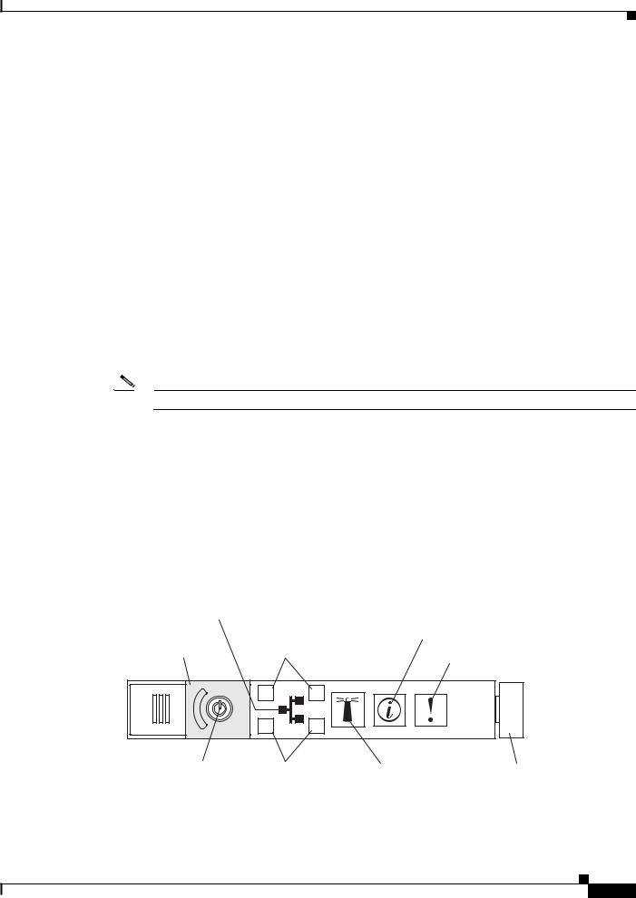
Figure 1-3 shows a detailed view of the controls and LEDs on the operator information panel.
Figure 1-3 Close Up of Cisco 8500 Operator Information Panel
Ethernet icon LED
Power-control |
Ethernet |
Information LED |
button cover |
activity LEDs |
System-error LED |
|
|
|
1 |
2 |
|
3 |
4 |
Power-control button/ |
Ethernet |
Locator button/ Release latch |
power-on LED |
activity LEDs locator LED |
|
255126
Cisco 8500 Series Wireless Controller Installation Guide
1-19

Chapter 1 Cisco 8500 Series Wireless Controller Installation Guide
Front Panel
Operator Information Panel Components
•Power-control button and power-on LED: Press this button to turn the controller on and off manually or to wake it from a reduced-power state. The states of the power-on LED are as follows:
–Off: Power is not present, or the power supply or the LED itself has failed.
–Flashing rapidly (4 times per second): The controller is turned off and is not ready to be turned on. The power-control button is disabled. This will last approximately 20 to 40 seconds.
–Flashing slowly (once per second): The controller is turned off and is ready to be turned on. You can press the power-control button to turn on the controller.
–Lit: The controller is turned on.
–Fading on and off: The controller is in a reduced-power state. To wake the controller, press the power-control button or use the IMM Web interface. See the Integrated Management Module User’s Guide for information on logging on to the IMM Web interface.
•Ethernet activity LEDs: When any of these LEDs is lit, they indicate that the controller is transmitting to or receiving signals from the Ethernet LAN that is connected to the Ethernet port that corresponds to that LED.
•System-locator button/LED: Use this blue LED to visually locate the controller among other servers. This LED is also used as a presence detection button. This LED is controlled by the IMM. When you press the System-locator button, the LED will blink and it will continue to blink until you press it again to turn it off. The locator button is pressed to visually locate the controller among the other servers.
•System-information LED: When this amber LED is lit, it indicates that a noncritical event has occurred. The IMM can be used to diagnose and correct the problem.
•System-error LED: When this amber LED is lit, it indicates that a system error has occurred. A system-error LED is also on the rear of the controller. An LED on the light path diagnostics panel on the operator information panel is also lit to help isolate the error. This LED is controlled by the IMM.
Light Path Diagnostics Panel
The light path diagnostics panel is on the top of the operator information panel, as shown in Figure 1-4. For additional information about the LEDs on the light path diagnostics panel, see Table 1-1.
To access the light path diagnostics panel, slide the blue release button on the operator information panel to the left. Pull forward on the unit until the hinge of the operator panel is free of the chassis. Then pull down on the unit, so that you can view the light path diagnostics panel information.
Note When you slide the light path diagnostics panel out of the controller to check the LEDs or checkpoint codes, do not run the controller continuously with the light path diagnostics panel outside of the controller. The panel should only be outside of the controller a short time. The light path diagnostics panel must remain in the controller when it is running to ensure proper cooling.
Cisco 8500 Series Wireless Controller Installation Guide
1-20

Chapter 1 Cisco 8500 Series Wireless Controller Installation Guide
Front Panel
Figure 1-4 Light Path Diagnostics Panel
Operator information panel
Light path diagnostics LEDs
Release latch
255127
Figure 1-5 shows the LEDs and controls on the light path diagnostics panel.
Figure 1-5 Light Path Diagnostics Panel Components
OVERSPEC LOG |
LINK |
PS |
PCI |
REMIND |
SP |
FAN |
TEMP |
MEM |
NMI |
NMI button |
|
||||
|
|
|
|
Checkpoint code |
CNFG CPU |
VRM |
DASD |
RAID |
BRD |
Light Path Diagnostics
RESET
255134
Light Path Diagnostics Panel Components
•Remind button: This button places the system-error LED on the front panel into Remind mode. In Remind mode, the system-error LED flashes once every 2 seconds until the problem is corrected, the controller is restarted, or a new problem occurs.
By placing the system-error LED indicator in Remind mode, you acknowledge that you are aware of the last failure but will not take immediate action to correct the problem. The Remind function is controlled by the IMM.
Cisco 8500 Series Wireless Controller Installation Guide
1-21
Loading...