


 Loading...
Installing and Formatting Cisco 2691, Cisco 3631 and Cisco 3700 CompactFlash Memory Cards
Product Numbers: MEM2691-32CF=, MEM2691-64CF=, MEM2691-128CF=, MEM3631-32CF=, MEM3631-64CF=, MEM3631-128CF=, MEM3725-32CF=, MEM3725-64CF=, MEM3725-128CF=, MEM3745-32CF=, MEM3745-64CF=, MEM3745-128CF=
This document describes how to install Cisco 2691, Cisco 3631, and Cisco 3700 CompactFlash memory cards in Cisco modular routers which use Cisco 2691, Cisco 3631, or Cisco 3700 CompactFlash memory. This document also contains procedures for formatting the CompactFlash cards with a Class B Flash file system (low end file system) or a Class C Flash file system (similar to DOS), and it describes how to perform file and directory operations in each file system. Some Cisco routers have an external CompactFlash memory card that resides in a slot in the rear panel; some have an internal CompactFlash memory card that mounts on a connector on the CPU/mainboard; and some have both. Cisco 2691, Cisco 3631, and Cisco 3700 CompactFlash memory cards are available with 32, 64, or 128 MB of memory.
Use this document with the Cisco 2600 Series, 3600 Series, and 3700 Series Regulatory Compliance and Safety Information document, which shipped with your router. If you have questions or need help, refer to the “Obtaining Documentation” section on page 31.
This document contains the following sections:
•Preventing Electrostatic Discharge Damage, page 2
•External CompactFlash Memory Card Installation and Removal, page 2
•Internal CompactFlash Memory Card Installation and Removal, page 4
•Formatting Procedures for CompactFlash Memory Cards, page 20
•File and Directory Procedures, page 23
•Obtaining Documentation, page 31
•Obtaining Technical Assistance, page 32
Corporate Headquarters: Cisco Systems, Inc., 170 West Tasman Drive, San Jose, CA 95134-1706 USA
A printed version of this document is an uncontrolled copy. Company Confidential |
78-13892-03 |
March 2002
Preventing Electrostatic Discharge Damage
Preventing Electrostatic Discharge Damage
CompactFlash memory cards are sensitive to electrostatic discharge (ESD) damage. ESD damage, which can occur when electronic cards or components are handled improperly, results in complete or intermittent failures.
Follow these guidelines to prevent ESD damage:
•Always use an ESD wrist or ankle strap and ensure that it makes good skin contact.
•Connect the equipment end of the strap to an unfinished chassis surface.
•Place a removed CompactFlash memory card on an antistatic surface or in a static shielding bag. If the card will be returned to the factory, immediately place it in a static shielding bag.
•Avoid contact between the card and clothing. The wrist strap protects the card from ESD voltages on the body only; ESD voltages on clothing can still cause damage.
•Do not remove the wrist strap until the installation is complete.
Caution For safety, periodically check the resistance value of the antistatic strap. The measurement should be between 1 and 10 megohms (Mohms).
Tools and Equipment Needed
You need the following tools and equipment to remove and install CompactFlash memory cards:
•ESD-preventive wrist strap
•Antistatic bag or mat
•Number 2 Phillips screwdriver or flat blade screwdriver (only for internally mounted CompactFlash memory cards)
External CompactFlash Memory Card Installation and Removal
Complete the appropriate procedure below for installing or removing a CompactFlash memory card if your Cisco router has an external CompactFlash memory card.
If you have questions or need assistance, see the “Obtaining Technical Assistance” section on page 32.
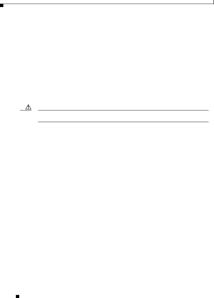
External CompactFlash memory-card slots are located as shown in Figure 1, Figure 2, and Figure 3.
Installing and Formatting Cisco 2691, Cisco 3631 and Cisco 3700 CompactFlash Memory Cards
2 |
78-13892-03 |
|
|
March 2002
External CompactFlash Memory Card Installation and Removal
Figure 1 External CompactFlash Slot Location in a Cisco 2691 Router
NM-HDV
BANK 4 |
|
|
|
|
|
2MFT-E1 |
|
AL |
SEE |
|
|
|
|
|
BANK 3 |
|
|
|
|
VWIC |
|
LP |
|
|
|
|
|
|
BANK |
2 |
BA |
|
|
CTRLR |
CD |
MANUAL |
|
|
|
|
|
|
|
|
NK 1 |
|
|
E2 |
BEFORE |
|
|
|
|
||
|
|
|
|
|
BANK 0 |
|
CTRLR E1 |
INSTALLATION |
TD |
RD |
LP |
AL |
|
|
|
|
|
|
|
|
|
V0 |
SEE |
|
|
CD |
|
|
|
|
|
|
MANUAL BEFORE |
|
DSU |
TD |
|
|
|
|
|
||
EN |
|
|
INSTALLATION |
56K |
RD |
LP |
AL |
|
CD |
|
|
|
|
|
|
|
SEE |
|
|
|
|
|
|
|
|
|
|
MANUAL BEFORE |
INSTALLATION |
DSU |
||
|
|
|
|
|
|
|
|
|
56K |
|
SEE MANUAL BEFORE INSTALLATION
Compact Flash slot
Figure 2 External CompactFlash Slot Location in a Cisco 3725 Router
NM-HDV
BANK 4 |
|
|
|
2MFT-E1 |
AL |
SEE |
|
|
|
|
|
BANK 3 |
|
|
VWIC |
LP |
|
|
|
|
|
|
BANK 2 |
|
|
CD |
MANUAL |
|
|
|
|
|
|
|
BANK 1 |
|
CTRLR E2 |
BEFORE |
|
|
|
|
|
|
|
|
BANK 0 |
CTRLR E1 |
INSTALLATION |
TD |
RD |
LP |
AL |
V0 |
SEE |
|
|
CD |
|
|
|
|
|
|
MANUAL BEFORE |
|
DSU |
TD |
|
|
|
|
|
||
|
INSTALLATION |
RD |
LP |
|
|
|
||||
EN |
|
|
56K |
AL |
|
CD |
||||
|
|
|
|
|
|
SEE |
|
|
|
|
|
|
|
|
|
|
MANUAL BEFORE |
INSTALLATION |
DSU |
||
|
|
|
|
|
|
|
|
|
56K |
|
SEE MANUAL BEFORE INSTALLATION
CF LED
Compact Flash
62484
62485
slot
Figure 3 External CompactFlash Slot Location in a Cisco 3745 Router
|
CONN |
|
|
|
SERIAL 1 |
|
|
|
|
|
|
|
|
|
|
|
|
|
|
|
|
|
|
SEE |
MANUAL |
BEFORE |
SERIAL 0 |
|
WIC |
|
|
|
|
|
|
|
|
|
|
|
|
|
|
|
|
|
|
|
INSTALLATION |
CONN |
2T |
TD |
RD |
|
|
|
|
|
|
|
|
|
|
|
|
|
|
|
|
|
|
|
|
|
LP |
AL |
|
|
|
|
|
|
|
|
|||
|
|
|
|
|
|
|
|
|
|
CD |
|
|
|
|
|
|
|
||||
|
|
|
|
|
|
|
|
|
|
SEE |
MANUAL BEFORE |
|
|
|
|
|
|
|
|||
|
|
|
|
|
|
|
|
|
|
|
INSTALLATION |
DSU |
|
|
|
|
|
|
|||
|
|
|
|
|
|
|
|
|
|
|
|
|
|
|
|
|
SERIAL 1 |
|
|
||
|
|
|
|
|
|
|
|
|
|
|
|
|
|
|
56K |
CONN |
|
|
|
|
|
|
|
|
|
|
|
|
|
|
|
|
|
|
|
|
|
SEE |
MANUAL |
BEFORE |
SERIAL 0 |
|
WIC |
|
|
|
|
|
|
|
|
|
|
|
|
|
|
|
|
|
INSTALLATION |
CONN |
|||
|
|
|
|
|
|
|
|
|
|
|
|
|
|
|
|
|
|
2T |
|||
BANK 4 |
|
|
|
|
|
VWIC |
|
|
AL |
|
|
|
|
|
|
|
|
|
|
|
|
BANK 3 |
|
|
|
|
|
|
LP |
|
|
|
|
|
|
|
|
|
|
|
|
||
|
BANK 2 |
|
|
2MFT-E1 |
|
|
|
SEE |
|
NM-HDV |
|
|
|
|
|
|
|
||||
|
|
BANK 1 |
|
|
CTRLR |
CD |
|
|
MANUAL |
|
|
|
|
|
|
|
|||||
NM-HDV |
|
|
|
|
|
BANK 0 |
|
|
CTRLR E1 |
INSTALLATION |
|
|
|
|
|
|
|
||||
|
|
|
|
|
|
|
|
|
|
|
|
|
|
|
|
|
|
|
|
|
|
V0
|
|
|
|
|
|
|
|
EN |
BANK 4 |
|
|
|
|
VWIC |
AL |
|
|
|
|
|
|
|
|
|
|
BANK |
3 |
BANK 2 |
|
2MFT-E1 |
LP |
BANK 4 |
BANK 3 |
|
|
|
VWIC |
AL |
|
|
|
|
|
BANK 1 |
BANK 0 |
CTRLR E2 |
|
|
BANK 2 |
|
|
2MFT-E1 |
LP |
SEE |
|
NM-HDV |
|
|
|
|
CTRLR E1 |
||
|
|
BANK 1 |
|
CTRLR |
CD |
MANUAL |
|
|
|
|
|
|
|
||
|
|
|
|
BANK 0 |
|
CTRLR E1 |
INSTALLATION |
|
|
|
|
|
|
|
|
V0
EN |
BANK 4 |
|
|
|
|
VWIC |
AL |
|
|
BANK 3 |
BANK 2 |
|
|
2MFT-E1 |
LP |
|
|
|
BANK 1 |
|
CTRLR |
CD |
|
|
|
|
|
|
BANK 0 |
|
CTRLR E1 |
CF LED
SEE |
MANUAL |
BEFORE |
INSTALLATION |
V0
EN
SEE
MANUAL
BEFORE
INSTALLATION
V0
EN
Compact Flash
slot
62486
Installing and Formatting Cisco 2691, Cisco 3631 and Cisco 3700 CompactFlash Memory Cards
|
78-13892-03 |
3 |
|
|
|

March 2002
Internal CompactFlash Memory Card Installation and Removal
Removing a CompactFlash Memory Card from an External Slot
Complete the following steps to remove a CompactFlash memory card from an external slot:
Caution If the CF LED is lit or blinking, do not remove the CompactFlash memory card. The router might reload, or the CompactFlash memory card can be damaged.
Step 1 Locate the CompactFlash memory card in its slot in the front panel of the chassis. (See Figure 1, Figure 2, and Figure 3.)
Step 2 Move the release button, located next to the slot, to its fully extended position, and press the button to unseat the card.
Step 3 Carefully pull the card out of the slot.
Step 4 Place the removed CompactFlash memory card on an antistatic surface or in a static shielding bag.
Installing a CompactFlash Memory Card in an External Slot
Complete the following steps to install a CompactFlash memory card:
Step 1 Locate the CompactFlash memory-card slot in the front panel of the chassis. (See Figure 1, Figure 2, and Figure 3.)
Step 2 With the label facing up, insert the connector end of the CompactFlash memory card into the slot until the card is seated in the connector and the release button is pushed out. The card is keyed so that it cannot be inserted wrong.
Step 3 Pull the release button out and move it to the left, to latch the card in the slot.
Step 4 Refer to the “Formatting Procedures for CompactFlash Memory Cards” section on page 20 for instructions on formatting the CompactFlash memory card.
Internal CompactFlash Memory Card Installation and Removal
Complete the appropriate procedure below for installing or removing a CompactFlash memory card mounted internally on the CPU/mainboard. To access the internal CompactFlash memory card, you need to either remove the chassis cover or slide the CPU/mainboard out, depending on the platform. For Cisco 2691, Cisco 3631, and Cisco 3725 routers, refer to the “Removing the Chassis Cover” section on page 9. For Cisco 3745 routers, refer to the “Removing a Plug-in CPU/Mainboard” section on page 7.
If you have questions or need assistance, see the “Obtaining Technical Assistance” section on page 32.
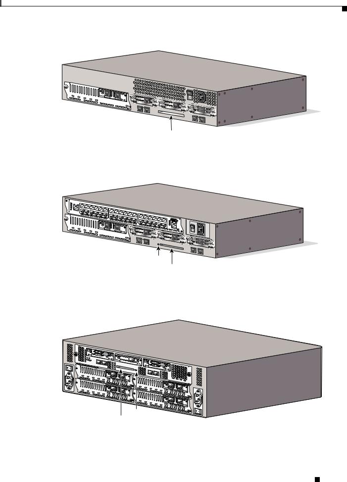
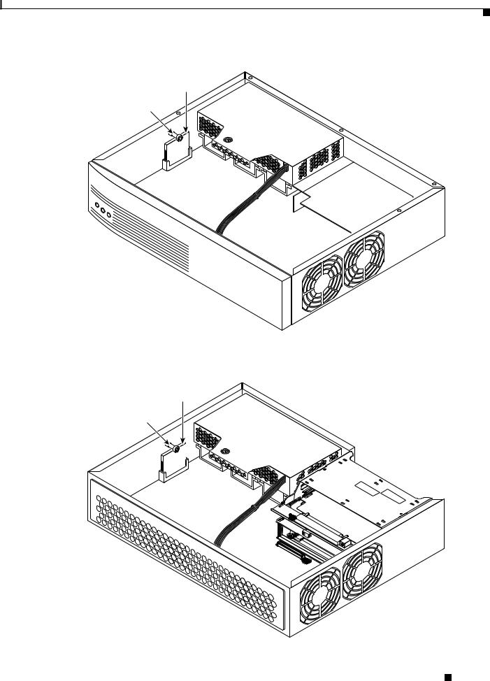
Internal CompactFlash memory card connectors are located as shown in Figure 4, Figure 5, Figure 6, and Figure 7.
Installing and Formatting Cisco 2691, Cisco 3631 and Cisco 3700 CompactFlash Memory Cards
4 |
78-13892-03 |
|
|
March 2002
Internal CompactFlash Memory Card Installation and Removal
Figure 4 Internal CompactFlash Memory Card Location in a Cisco 2691
Compact Flash
memory card
Retention screw
62478
Figure 5 Internal CompactFlash Memory Card Location in a Cisco 3631
Compact Flash
memory card
Retention screw
62479
Installing and Formatting Cisco 2691, Cisco 3631 and Cisco 3700 CompactFlash Memory Cards
|
78-13892-03 |
5 |
|
|
|

March 2002
Internal CompactFlash Memory Card Installation and Removal
Figure 6 Internal CompactFlash Memory Card Location in a Cisco 3725
Compact Flash
memory
Retention screw
62480
Figure 7 Internal CompactFlash Memory Card Location in a Cisco 3745
Compact Flash
memory card
62487
Plug-in mainboard
Installing and Formatting Cisco 2691, Cisco 3631 and Cisco 3700 CompactFlash Memory Cards
6 |
78-13892-03 |
|
|
March 2002
Internal CompactFlash Memory Card Installation and Removal
Removing a Plug-in CPU/Mainboard
This section describes how to access a CompactFlash memory card mounted on a CPU/mainboard that slides out of the chassis. You need a number 2 Phillips or flat-blade screwdriver to complete this procedure.
Cisco 3745 routers have a plug-in CPU/mainboard.
Observe the following precaution if your router uses AC power:
Warning Do not touch the power supply when the power cord is connected. For systems with a power switch, line voltages are present within the power supply even when the power switch is OFF and the power cord is connected. For systems without a power switch, line voltages are present within the power supply when the power cord is connected. To see translations of the various warnings that appear in this publication, refer to the Regulatory Compliance and Safety Information document that accompanied this device.
Observe the following precaution if your router uses DC power:
Warning Before performing any of the following procedures, ensure that power is removed from the DC circuit. To ensure that all power is OFF, locate the circuit breaker on the panel board that services the DC circuit, switch the circuit breaker to the OFF position, and tape the switch handle of the circuit breaker in the OFF position. To see translations of the various warnings that appear in this publication, refer to the Regulatory Compliance and Safety Information document that accompanied this device.
Complete the following procedure to remove the CPU/mainboard from the chassis:
Step 1 Power OFF the router. However, to channel ESD voltages to ground, do not unplug the power cable.
Caution The Cisco 3745 can have more than one power supply. Be sure that all power supplies are powered OFF, and that the LEDs are all dark.
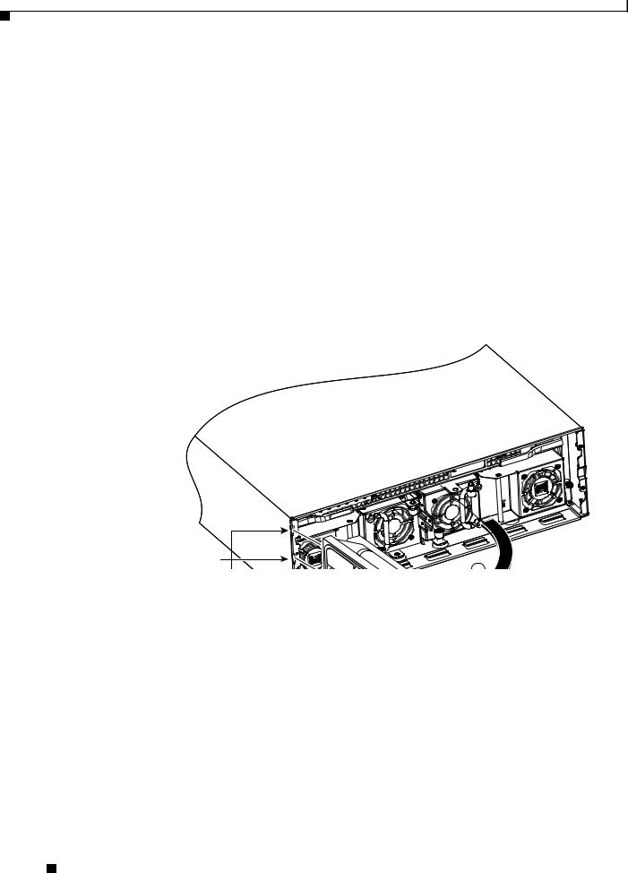
Step 2 Place the router on a flat surface so that the front panel is facing you, and open the small access panel at the right-hand edge of the front panel.
Step 3 Loosen the two captive screws located behind the access panel. (See Figure 8.)
Step 4 Open the front panel to the straight-out position, and lift it off its hinges. (See Figure 8.)
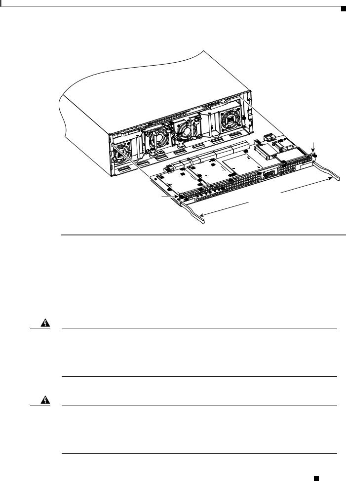
Step 5 Loosen the captive retention screws; there is one at each side of the CPU/mainboard. (See Figure 9.)
Step 6 Pull the ejector levers at both sides, and carefully pull the CPU/mainboard straight out of the chassis. Place it on an antistatic surface. (See Figure 9.)
Step 7 When you are ready to reinstall the CPU/mainboard, refer to the “Reinstalling a Plug-in CPU/Mainboard” section on page 14.
Installing and Formatting Cisco 2691, Cisco 3631 and Cisco 3700 CompactFlash Memory Cards
|
78-13892-03 |
7 |
|
|
|
March 2002
Internal CompactFlash Memory Card Installation and Removal
Figure 8 Removing the Front Panel from a Cisco 3745 Router
62481
Hinges
Installing and Formatting Cisco 2691, Cisco 3631 and Cisco 3700 CompactFlash Memory Cards
8 |
78-13892-03 |
|
|
March 2002
Internal CompactFlash Memory Card Installation and Removal
Figure 9 Removing the CPU/Mainboard from a Cisco 3745 Router
Captive retention screw
Captive |
Ejector levers |
retention |
|
screw |
|
Removing the Chassis Cover
This section describes how to remove the chassis cover to access internally mounted CompactFlash memory cards. You need a number 2 Phillips or flat-blade screwdriver to complete this procedure.
You must remove the chassis cover from Cisco 2691, Cisco 3631, and Cisco 3725 routers.
Observe the following precaution if your router uses AC or DC power:
Warning Do not touch the power supply when the power cord is connected. For systems with a power switch, line voltages are present within the power supply even when the power switch is OFF and the power cord is connected. For systems without a power switch, line voltages are present within the power supply when the power cord is connected. To see translations of the various warnings that appear in this publication, refer to the Regulatory Compliance and Safety Information document that accompanied this device.
Observe the following precaution if your router uses DC power:
Warning Before performing any of the following procedures, ensure that power is removed from the DC circuit. To ensure that all power is OFF, locate the circuit breaker on the panel board that services the DC circuit, switch the circuit breaker to the OFF position, and tape the switch handle of the circuit breaker in the OFF position. To see translations of the various warnings that appear in this publication, refer to the Regulatory Compliance and Safety Information document that accompanied this device.
Installing and Formatting Cisco 2691, Cisco 3631 and Cisco 3700 CompactFlash Memory Cards
|
78-13892-03 |
9 |
|
|
|

March 2002
Internal CompactFlash Memory Card Installation and Removal
Complete the following procedure to remove the chassis cover:
Step 1 Power OFF the router. However, to channel ESD voltages to ground, do not unplug the power cable.
Warning Before opening the chassis, disconnect the telephone-network cables to avoid contact with telephone-network voltages. To see translations of the various warnings that appear in this publication, refer to the Regulatory Compliance and Safety Information document that accompanied this device.
Step 2 Disconnect all network interface cables from the rear panel.
Step 3 Place the router on a flat surface. Remove the screws located on top of the cover (five screws on a Cisco 2691 or Cisco 3631 router; six screws on a Cisco 3725 router). Set the screws aside in a safe place.
Step 4 Rotate the cover up to a 45-degree angle. (See Figure 10, Figure 11, or Figure 12.)
Step 5 Slide the cover to the side (away from the side with the fans) until the tabs are free from the slots. (See Figure 10, Figure 11, or Figure 12.)
To replace the cover, see the “Reinstalling the Cover on a Cisco Router” section on page 16.
Installing and Formatting Cisco 2691, Cisco 3631 and Cisco 3700 CompactFlash Memory Cards
10 |
78-13892-03 |
|
|
March 2002
Internal CompactFlash Memory Card Installation and Removal
Figure 10 Removing the Cover from a Cisco 2691
1
62482
1 |
Lift cover |
2 |
Slide cover |
|
|
|
|
Installing and Formatting Cisco 2691, Cisco 3631 and Cisco 3700 CompactFlash Memory Cards
|
78-13892-03 |
11 |
|
|
|
Loading...