


CG8010DX16

CG8010
Data Sheet
品 名:POWER SUPPLY SUPER VISOR
WITH PWM CONTROLLER
奇高料號:CG8010
版 本:Rev 0.30
日 期:October 4, 2007
頁 數:8 頁
發文日期:2007/10/05
October 4, 2007 – Rev. 0.30
YT
CG8010
POWER SUPPLY SUPERVISOR WITH PWM CONTROLLER
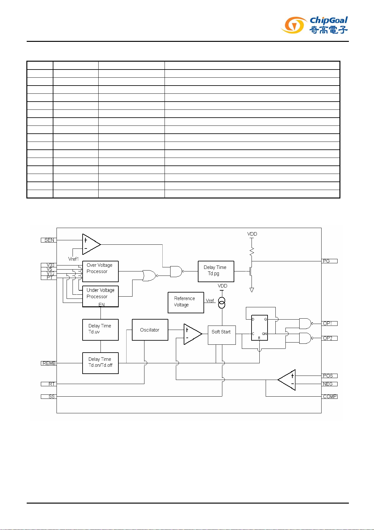
complete power supervisor for use in the switched mode power supply .
It contains various functions, like under voltage protection (UVP), over voltage
protection (OVP), power good output (PG) and ON/OFF control (REM).
UVP(Under voltage protection) function is for +3.3V, +5V, +12V outputs.
OVP(Over voltage protection) function is for +3.3V, +5V, +12V and PT is for
extra protection input.
PG(Power good signal) is a safe operation signal to inform the external parts.
REM(Remote on/off) is used to control the SMPS on/off. The REM control
signal has the on/off transferred debounce–time.
FEATURE
■ 3-channel under voltage protection (UVP)
■ 3-channel over voltage protection (OVP)
■ 1-channel extra protection (PT)
■ 1-channel sense input to control the PG (SEN)
■ Remote on/off control function (REM)
■ Dual output for push-pull operation (OP1/OP2)
■ Soft start capability by external capacitor (SS)
■ VCC under voltage lockout
■ 16-Pin dual in-line package
■ Pb-free Package are available
ORDERING INFORMATION
ORDER NUMBER Package Shipping Top Marking
CG8010DX16 DIP-16 (Pb-free) Tube CG8010DX16
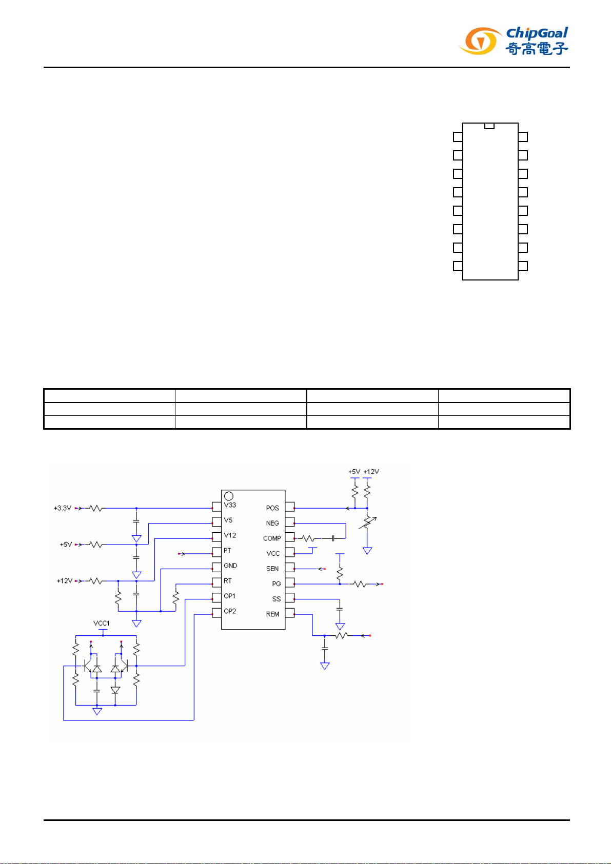
REFERENCE APPLICA TION CIRCUIT
PIN CONFIGURATION (Top View) The CG8010 is designed with a pulse-width-modulation control circuit and a
V33
V5
V12
PT
GND
RT
OP1
OP2
1
2
3
4
5
6
7
8
16
15
14
13
12
11
10
POS
NEG
COMP
VCC
SEN
PG
SS
REM
9
October 4, 2007 – Rev. 0.30 datasheet
YT 1
CG8010
POWER SUPPLY SUPERVISOR WITH PWM CONTROLLER
PIN DESCRIPTION
Pin Symbol Type Function
1 V33 I OVP, UVP for +3.3V
2 V5 I OVP, UVP for +5V
3 V12 I OVP, UVP for +12V
4 PT I Extra protection input
5 GND - Ground
6 RT - Oscillation frequency setting resistor
7 OP1 O PWM output1
8 OP2 O PWM output2
9 REM I Remote ON/OFF control input
10 SS - Soft start function setting capacitor
11 PG O Power good signal
12 SEN I Sense signal input
13 VCC I Supply voltage
14 COMP O Error amplifier output
15 NEG I Error amplifier (-) input
16 POS I Error amplifier (+) input
FUNCTION BLOCK DIAGRAM
October 4, 2007 – Rev. 0.30 datasheet
YT 2
 Loading...