


 Loading...
Belt Drive Battery Backup Garage Door Opener
Models
HD920EV • 349544 • WD962KEV • WD962KPEV
FOR RESIDENTIAL USE ONLY
■Please read this manual and the enclosed safety materials carefully!
■Fasten the manual near the garage door after installation.
■ The door WILL NOT CLOSE unless the Protector System® is connected and properly aligned.
■ Periodic checks of the garage door opener are required to ensure safe operation.
■ The model number label is located on the left side panel of your garage door opener.
■This garage door opener is compatible with MyQ™ and Security 2.0™ accessories.
■DO NOT enable the Timer-to-Close feature if you are installing the garage door opener on a one-piece door. The Timer-to-Close is to be used ONLY with sectional doors.
Write down the following information for future reference:
Model Number:
Serial Number: |
. |
|
www.chamberlain.com |
||
|
||
Date of Purchase: |
The Chamberlain Group, Inc. |
|
|
845 Larch Avenue |
|
|
Elmhurst, Illinois 60126-1196 |
CONTENTS
Preparation . . . . . . . . . . . . . . . .2-5
Assembly . . . . . . . . . . . . . . . . 6-10
Installation . . . . . . . . . . . . . . 11-20
Install the Door Control . . . . . . 21-23
Install the Protector System® . . 23-26
Power. . . . . . . . . . . . . . . . . . 27-28
Adjustments . . . . . . . . . . . . . 29-31
Battery Backup. . . . . . . . . . . . 32-33
Operation . . . . . . . . . . . . . . . . . 34
Features . . . . . . . . . . . . . . . . . . 35
Door Control . . . . . . . . . . . . . 36-38
Remote Control . . . . . . . . . . . 39-40
To Erase the Memory . . . . . . . . . 40
To Open the Door Manually . . . . . 41
Maintenance . . . . . . . . . . . . . . . 42
Troubleshooting. . . . . . . . . . . 43-44
Repair Parts . . . . . . . . . . . . . 45-46
Accessories. . . . . . . . . . . . . . . . 47
Warranty. . . . . . . . . . . . . . . . . . 48
Preparation
Safety Symbol and Signal
Word Review
Thisgarage door opener hasbeen designed and tested to offer safe service provided itisinstalled, operated,maintained and tested in strict accordance with the instructionsand warnings contained in thismanual.
When you see these SafetySymbolsand Signal Wordson the following pages,theywill alertyou to the possibilityofserious injury ordeathifyou do notcomplywith the warningsthataccompany them.The hazard maycome fromsomething mechanical or fromelectricshock.Read the warningscarefully.
Mechanical
Electrical
When you see thisSignal Word on the following pages,itwill alertyou to the possibilityofdamage to your garage door and/or the garage door opener ifyou do notcomplywith the cautionary statementsthataccompanyit.Read them carefully.
Check the Door
1.Disable locksand remove anyropes connected to the garage door.
2.Liftthe door halfwayup.Release the door.Ifbalanced,itshould stayin place,supported entirelybyitssprings.
3.Raise and lower the door to checkfor binding or sticking.Ifyour door binds, sticks,or isoutofbalance,call a trained door systemstechnician.
4.Checkthe seal on the bottomofthe door.Anygap between the floor and the bottomofthe door mustnotexceed 1/4 inch (6 mm).Otherwise,the safety reversal systemmaynotworkproperly.
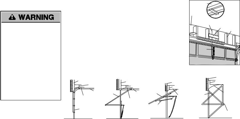
5.The opener should be installed above the center ofthe door.Ifthere isa torsion spring or center bearing plate in the wayofthe header bracket,itmay be installed within 4 feet(1.2 m) to the leftor rightofthe door center.
See page 13.
Torsion Spring OR Extension Spring
To preventpossible SERIOUS NJURY or DEATH:
•ALWAYS call a trained door systems technician ifgarage door binds,sticks,or isoutofbalance.An unbalanced garage door mayNOTreverse when required.
•NEVERtryto loosen,move or adjust garage door,door springs,cables, pulleys,bracketsor their hardware, ALL ofwhich are under EXTREME tension.
•Disable ALL locksand remove ALL ropes connected to garage door BEFORE installation and operating garage door opener to avoid entanglement.
To preventdamage to garage door and opener:
•ALWAYS disable locksBEFORE installing and operating the opener.
•ONLY operate garage door opener at 120 V,60 Hzto avoid malfunction and damage.
2
Preparation
üAdditional items you may need:
Surveyyour garage area to see ifyou will need anyofthe following items:
q(2) 2X4 PIECES OFWOOD
Maybe used to fasten the header bracketto the structural supports.Also used to position the garage door opener during installation and for testing the safetyreversing sensors.
qSUPPORTBRACKETANDFASTENING HARDWARE
Mustbe used ifyou have a finished ceiling in your garage.
qEXTENSIONBRACKETS (MODEL 41A5281) ORWOODBLOCKS
Depending upon garage construction, extension bracketsor wood blocksmaybe needed to install the safetyreversing sensor.
qFASTENING HARDWARE
Alternate floor mounting ofthe safety reversing sensor will require hardware not provided.
qOUTSIDE QUICKRELEASE (MODEL7702CB)
Required for a garage with NO accessdoor.
qDOORREINFORCEMENT
Required ifyou have a lightweightsteel, aluminum,fiberglassor glasspanel door.
qRAILEXTENSIONKIT
Required ifyour garage door ismore than 7 feet(2.13 m) high.
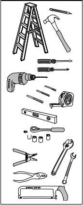
Tools Needed
5/32 3/16 

5/16
1 |
2 |
1/2 

5/8 |
1/4 |
7/16 9/16
7/16
3
Preparation
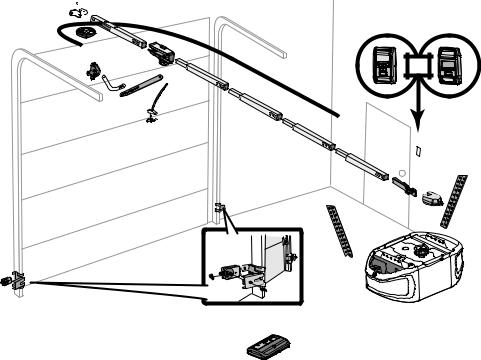
Carton Inventory
Your garage door opener ispackaged in one carton which containsthe motor unitand all partsillustrated below.Accessoriesvarydepending on the garage door opener model purchased.Depending on your model,other accessoriesmaybe included with your garage door opener.Instructionsfor these accessorieswill be attached to the accessoryand are notincluded in thismanual.Ifanything ismissing,carefully checkthe packing material.Partsmaybe stuckin the foam.Hardware for assemblyand installation isshown on the nextpage.Save the carton and packing material until the installation and adjustmentis complete.The imagesthroughoutthismanual are for reference onlyand your productmaylookdifferent.
A.Header bracket
B.Pulley
C.Door bracket
D.Curved door arm
E.Straight door arm (Packaged inside rail section)
F.Trolley
NOTE: Be sure to assemble the trolley before sliding onto rail.
G.Emergency release rope and handle
H.Rail (1 front and 4 center sections)
I.Hanging brackets (2) (Packaged inside rail section)
J.Garage door opener
K.Sprocket cover and screws
L.“U” bracket
M.Belt
N.Door control (Motion-Detecting Control Panel or Smart Control Panel®)
O.Remote control
P.The Protector System®
Safety reversing sensors with 2 conductor white and white/black wire attached: Sending Sensor (1), Receiving Sensor (1), and Safety Sensor Brackets (2)
NOT SHOWN
White and red/white wire
Owner's manual
A 
|
B |
|
C |
F |
OR |
|
D |
|
M
E
 G
G
H
K
L
I
P
J
O
4
Preparation
Carton Inventory
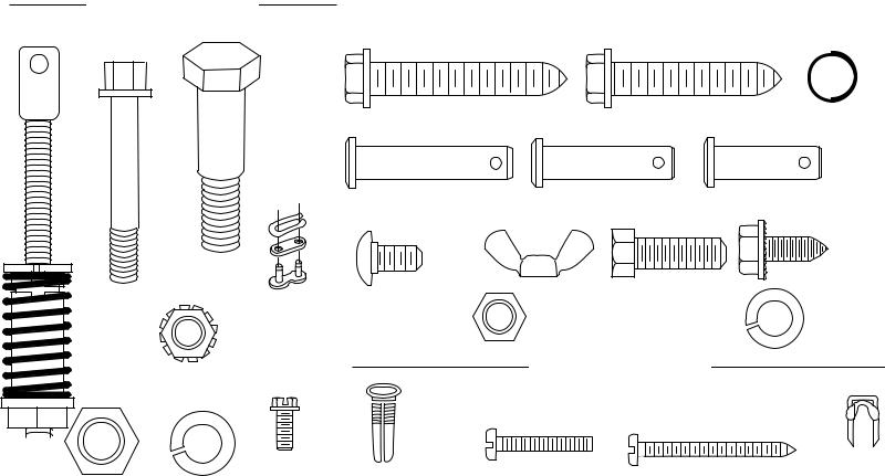
ASSEMBLY HARDWARE
H2 |
H3 |
Bolt |
Bolt |
1/4"-20x1-3/4" (2) |
|
H1
Threaded Shaft with
H8
Spring Trolley Nut
H4
Lock Nut 1/4"-20 (2)
H6 |
H7 |
|
Nut 3/8" |
||
Lock Washer 3/8" |
||
|
|
INSTALLATION HARDWARE |
|
|
|
|
H10 |
H11 |
H19 |
Lag Screw 5/16"-18x1-7/8" (2) |
Lag Screw 5/16"-9x1-5/8" (2) |
Ring Fastener (3) |
H12 |
|
H13 |
|
H14 |
Clevis Pin 5/16"x1-1/2" |
|
Clevis Pin 5/16"x1-1/4" |
Clevis Pin 5/16"x1" |
|
H5 |
|
|
|
H16 |
Master Link |
H18 |
|
H15 |
|
H17 |
|
Self-Threading Screw |
||
Carriage Bolt 1/4"-20x1/2" (2) |
Wing Nut 1/4"-20 (2) |
Hex Bolt 5/16"-18x7/8" (4) |
1/4"-14x5/8" (2) |
|
|
||||
H20 |
H21 |
Nut 5/16"-18 (8) |
Lock Washer 5/16"-18 (7)
H9
Hex Screw #8x3/8" (3)
(packed with the DOOR CONTROL HARDWARE
sprocket cover)
|
Screw 6-32x1" (2) |
Screw 6ABx1-1/2" (2) |
|
|
|
|
|
Insulated |
Drywall Anchors (2) |
|
Staples |
5
Assembly
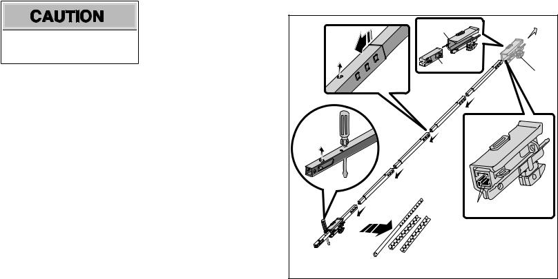
1 Assemble the rail and trolley
To prevent NJURY frompinching,keep hands and fingersawayfromthe jointswhile assembling the rail.
Toavoidinstallationdifficulties,donot runthe garage dooropeneruntilinstructedtodoso.
1.1Assemble the trolleybysliding the inner trolleyinto the outer trolley.
1.2Carefullyremove the straightdoor arm and hanging bracketspackaged inside the frontrail.
1.3Align the railson a flatsurface asshown. The frontrail hasa cutoutwindownear the end.Make sure thatthe larger hole on the frontrail isfacing up.
1.4Slide the tapered end ofeach rail section into the larger end ofthe rail section in frontofit.The tabsalong the side will lock in place.All holesin the rail sections should face up.
1.5Inserta screwdriver into the hole shown (thiswill temporarilykeep the trolleyfrom sliding offthe end ofthe rail).
1.6Checkto make sure thatthe 4 plasticwear padsare inside the inner trolley.Iftheyare missing checkall the packing material and snap thembackinto place.
1.7Slide the trolleyalong the rail toward the screwdriver asshown.
Outer Trolley |
To garage |
|
door opener |
||
|
||
Inner Trolley |
|
|
|
Trolley |
|
|
Wear Pads |
6
Assembly
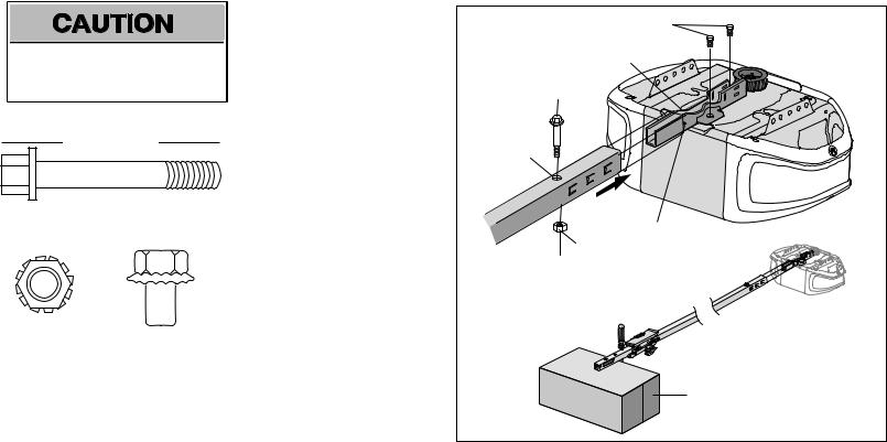
2 Fasten the rail to the garage door opener
To avoid SERIOUS damage to garage door opener,use ONLY those bolts/fasteners mounted in the top ofthe opener.
HARDWARE
H2
Bolt 1/4"-20x1-3/4"
H4 |
(Mounted in the |
||||
Lock Nut 1/4"-20 |
garage door opener) |
||||
|
|
|
|
|
|
|
|
|
|
|
|
|
|
|
|
|
|
|
|
|
|
|
|
|
|
|
|
|
|
|
|
|
|
|
|
NOTE: ONLY use the boltsremoved fromthe garage door opener.Place the garage door opener on the packing material to prevent scratching.
2.1Insertthe bolt(H2) into the hole on the backend ofthe rail asshown.Tighten securelywith the locknut(H4).Do not overtighten.
2.2Remove the two boltsfromthe top ofthe garage door opener.
2.3Place the “U” bracket,flatside down onto the garage door opener and align the brackethole with the boltholes.Fasten the “U” bracketwith the previouslyremoved bolts.
2.4Prop up the end ofthe rail on the carton to help align itwith the “U” bracket.
2.5Slide the rail onto the “U” bracket,until it reachesall the stopson the top and sides ofthe “U” bracket.
|
Bolts |
|
|
“U” Bracket |
|
H2 |
|
|
Cover |
|
|
Protection |
|
|
Bolt Hole |
|
|
|
SLIDE RAIL TO |
|
H4 |
STOPS ON TOP AND |
|
SIDES |
||
|
||
|
Carton |
7
Assembly
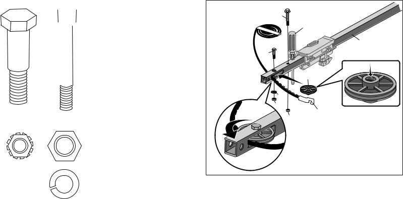
3 Install the pulley
|
HARDWARE |
|
|
|
|
|||
H3 |
|
|
|
|
||||
|
H2 |
|
|
|
|
|||
Bolt |
|
Bolt 1/4"-20x1-3/4" |
||||||
|
|
|
|
|
|
|
|
|
|
|
|
|
|
|
|
|
|
|
|
|
|
|
|
|
|
|
|
|
|
|
|
|
|
|
|
H4 |
H6 |
Lock Nut 1/4"-20 |
Nut 3/8" |
H7
Lock Washer 3/8"
3.1Laythe beltbeside the rail,asshown. Grasp the end with the hooked trolley connector and passapproximately12" (30 cm) ofbeltthrough the window.Keep the ribbed side toward the rail,and allowitto hang.
3.2Remove the tape fromthe pulley.The center should be greased,ifnot,regrease the center ofthe pulley.
3.3Insertthe pulleyinto the windowofthe frontrail.
3.4Insertthe bolt(H3) into the rail and pulley. Tighten securelywith the lockwasher (H7) and nut(H6).
3.5Rotate the pulleyto be sure itspinsfreely.
3.6Insertthe bolt(H2) into the hole shown and fasten with the locknut(H4).
H2 |
|
|
|
Screwdriver |
|
|
Rail |
|
H3 |
|
|
|
Pulley |
|
H7 |
|
|
H6 |
|
|
H4 |
Trolley |
|
Connector |
||
|
8
Assembly
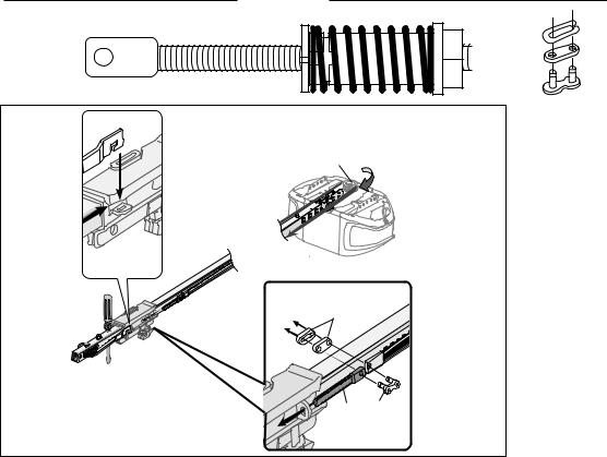
4 Install the belt
4.1 Pull the beltaround the pulleyand toward |
H1 |
HARDWARE |
H5 |
the trolley.The ribbed side mustcontact |
|
||
the pulley. |
Threaded |
Shaft |
Master Link |
4.2 Hookthe trolleyconnector into the |
with |
|
|
H8 |
|
|
|
retaining sloton the trolleyasshown. |
|
|
|
4.3 With the trolleyagainstthe screwdriver, |
Spring |
|
|
Trolley Nut |
|
||
dispense the remainder ofthe beltalong |
|
||
|
|
|
|
the rail length toward the motor unitand |
|
|
|
around the sprocket.The sprocketteeth |
|
|
|
mustengage the belt. |
|
|
|
4.4 Checkto make sure the beltisnottwisted. |
|
Sprocket |
|
Connectthe trolleythreaded shaft(H1) |
|
|
|
with the master link(H5). |
|
|
|
• Push pinsofmaster linkbar through |
|
|
|
holesin end ofbeltand trolleythreaded |
|
|
|
shaft(H1). |
|
|
|
• Push master linkcap over pinsand past |
|
|
|
pin notches. |
|
|
|
• Slide clip-on spring over cap and onto |
|
|
|
pin notchesuntil both pinsare securely |
|
|
|
locked in place. |
|
|
|
4.5 Remove the spring trolleynut(H8) from |
|
H5 |
|
the threaded shaft(H1). |
|
|
|
4.6 Insertthe trolleythreaded shaft(H1) |
|
|
|
through the hole in the trolley. |
|
|
|
|
|
H1 |
H5 |
|
|
9 |
|

Assembly
5 Tighten the belt and install the sprocket cover
To avoid possible SERIOUS NJURY to finger frommoving garage door opener:
•ALWAYS keep hand clear ofsprocketwhile operating opener.
•Securelyattach sprocketcover BEFORE operating.
HARDWARE
H8 |
H9 (3) |
Spring Trolley Nut |
|
|
Hex Screw #8x3/8" |
|
(Packed with the |
|
sprocket cover) |
5.1Byhand,thread the spring trolleynuton the threaded shaft(H8) until itisfinger tight againstthe trolley.Do notuse anytools. Remove the screwdriver.
(to motor unit)
H8
5.2Inserta flathead screwdriver tip into one ofthe nutring slotsand brace itfirmly againstthe trolley.
Nut ring slot
5.3Tighten the spring trolleynutwith an adjustable wrench or a 7/16" open end wrench abouta quarter turn until the spring releasesand snapsthe nutring againstthe trolley.Thissetsthe spring to optimumbelttension.
Nut Ring |
Nut Ring |
BEFORE |
AFTER |
1" |
1-1/4" |
(2.5 cm) |
(3.18 cm) |
5.4Position the sprocketcover over the garage door opener sprocketand attach with hex screws(H9).
H9
10
Installation
IMPORTANT INSTALLATION INSTRUCTIONS
To reduce the risk of SEVERE INJURY or DEATH:
1.READANDFOLLOWALL INSTALLATIONWARNINGS ANDINSTRUCTIONS.
2.Install garage door opener ONLY on properlybalanced and lubricated garage door.An improperlybalanced door mayNOTreverse when required and could resultin SEVERE INJURY or DEATH.
3.ALL repairsto cables,spring assembliesand other hardware MUSTbe made bya trained door systemstechnician BEFORE installing opener.
4.Disable ALL locksand remove ALL ropesconnected to garage door BEFORE installing opener to avoid entanglement.
5.Install garage door opener 7 feet(2.13 m) or more above floor.
6.Mountthe emergencyrelease within reach,butatleast6 feet(1.83 m) above the floor and avoiding contactwith vehiclesto avoid accidental release.
7.NEVERconnectgarage door opener to power source until instructed to do so.
8.NEVERwear watches,ringsor loose clothing while installing or servicing opener.Theycould be caughtin garage door or opener mechanisms.
9.Install wall-mounted garage door control:
•within sightofthe garage door.
•outofreach ofchildren atminimumheightof5 feet(1.5 m).
•awayfromALL moving partsofthe door.
10.Place entrapmentwarning label on wall nextto garage door control.
11.Place manual release/safetyreverse testlabel in plain viewon inside ofgarage door.
12.Upon completion ofinstallation,testsafetyreversal system.Door MUSTreverse on contact with a 1-1/2"(3.8 cm) high object(or a 2x4 laid flat) on the floor.
13.To avoid SERIOUS PERSONAL NJURY or DEATHfromelectrocution,disconnectALL electricand batterypower BEFORE performing anyservice or maintenance.
14.DO NOTenable the Timer-to-Close functionalityifoperating either one-piece or swinging garage doors.To be enabled ONLY when operating a sectional door.
11
Installation
1 Determine the header bracket location
To preventpossible SERIOUS INJURY or DEATH:
•Header bracketMUSTbe RIGIDLY fastened to structural supporton header wall or ceiling,otherwise garage door might NOTreverse when required.DO NOT install header bracketover drywall.
•Concrete anchorsMUSTbe used if mounting header bracketor 2x4 into masonry.
•NEVERtryto loosen,move or adjust garage door,springs,cables,pulleys, brackets,or their hardware,ALL ofwhich are under EXTREME tension.
•ALWAYS call a trained door systems technician ifgarage door binds,sticks,or is outofbalance.An unbalanced garage door mightNOTreverse when required.
Installation proceduresvaryaccording to garage door types.Followthe instructionswhich applyto your |
Unfinished |
|
OPTIONAL |
door. |
|
||
Ceiling |
|
CEILING |
|
1.1 Close the door and markthe inside vertical centerline ofthe garage door. |
|
||
|
|
MOUNT FOR |
|
1.2 Extend the line onto the header wall above the door. |
Header Wall |
2x4 |
HEADER |
Youcanfastenthe headerbracket within4 feet (1.22 m) of the left orright of the door |
|
BRACKET |
|
|
|
||
Vertical Centerline |
|
|
|
centeronly if a torsionspringorcenterbearingplate is inthe way; oryoucanattachit to |
|
|
|
of Garage Door |
2x4 |
Structural |
|
the ceilingwhenclearance is minimal.(It may be mountedonthe wallupside downif |
|
||
|
|
Supports |
|
necessary,togainapproximately 1/2" (1 cm). |
|
|
|
|
|
|
|
Ifyou need to install the header bracketon a 2x4 (on wall or ceiling),use lag screws(not |
|
|
|
provided) to securelyfasten the 2x4 to structural supports. |
|
|
|
1.3 Open your door to the highestpointoftravel asshown.Drawan intersecting horizontal line on |
|
|
|
the header wall 2" (5 cm) above the high point. |
Level |
|
|
• 2" (5 cm) above the high pointfor sectional door and one-piece door with track. |
|
|
|
(Optional) |
|
|
|
• 8" (20 cm) above the high pointfor one-piece door withouttrack.Thisheightwill provide travel |
|
|
|
clearance for the top edge ofthe door.NOTE: Ifthe total number ofinchesexceedsthe height |
|
|
|
available in your garage,use the maximumheightpossible,or refer to page 13 for ceiling |
|
|
|
installation. |
|
|
|
Header Wall |
Header Wall |
|
|
2" (5 cm) |
2" (5 cm) |
|
Track |
Door |
Track |
|
||
|
|
Highest Point
of Travel Highest Point
of Travel
Door
|
|
|
Header Wall |
|
|
Header Wall |
|
8" (20 cm) |
|
|
8" (20 cm) |
|
|
|
Door |
Highest |
|
Highest |
|
Door |
Point of |
|||
|
||||
|
Point of |
|
Travel |
|
|
Travel |
|
||
|
|
|
Jamb
Hardware
Pivot
Sectional door with |
One-piece door with |
One-piece door without track: |
One-piece door without track: |
curved track |
horizontal track |
jamb hardware |
pivot hardware |
12
Installation
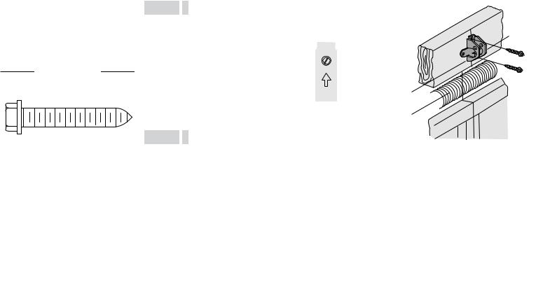
2 Install the Header Bracket
You can attach the header bracketeither to the wall above the garage door,or to the ceiling. Followthe instructionswhich will workbestfor your particular requirements.Donot installthe headerbracket overdrywall.If installinginto masonry,use concrete anchors (not provided).
HARDWARE
H11 (2)
Lag Screw 5/16"-9x1-5/8"
OPTION A WALL INSTALLATION
2.1A Center the bracketon the vertical centerline with the bottomedge ofthe bracketon the horizontal line asshown (with the arrowpointing toward the ceiling).
2.2A Markthe vertical setofbracketholes(do notuse the holesdesignated for ceiling mount).Drill 3/16" pilotholesand fasten the bracketsecurelyto a structural supportwith the hardware provided (H11).
OPTION B CEILING INSTALLATION
2.1B Extend the vertical centerline onto the ceiling asshown.
2.2B Center the bracketon the vertical mark, no more than 6" (15 cm) fromthe wall. Make sure the arrowispointing away fromthe wall.The bracketcan be mounted flush againstthe ceiling when clearance isminimal.
2.3B Markthe side holes.Drill 3/16" pilotholes and fasten bracketsecurelyto a structural supportwith the hardware
provided (H11).
|
(Header Wall) |
Vertical |
|
Centerline of |
|
Wall Mount |
|
|
|
Garage Door |
|
|
|
|
|
2x4 Structural |
|
|
Support |
|
|
Header |
|
|
Bracket |
H11 |
UP |
|
|
|
|
|
|
Horizontal |
Door Spring |
|
|
|
|
Line |
|
Highest Point of
Garage Door
Optional Travel (Garage Door)
Mounting
Holes
|
Header |
(Finished Ceiling) |
|
Bracket |
|
|
|
|
Ceiling Mounting Holes |
6" (15 cm) |
|
|
Maximum |
|
|
Door Spring |
Vertical |
|
Centerline of |
|
|
|
|
|
|
Garage Door |
UP |
|
|
|
|
H11 |
|
|
(Header Wall) |
|
(Garage Door) |
|
13
Installation
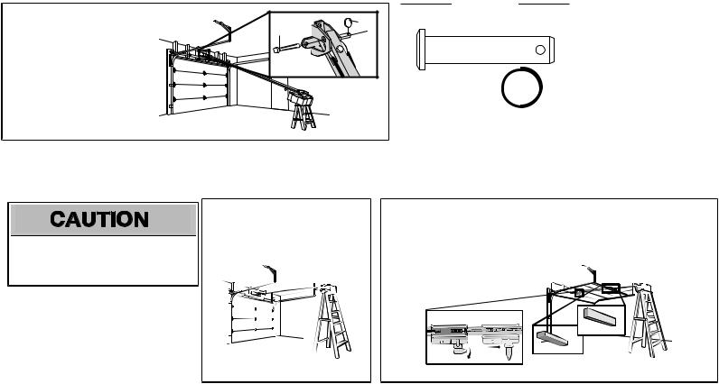
3 Attach the rail to the header bracket
HARDWARE
3.1Align the rail with the header bracket.Insertthe clevispin (H12) through the holesin the header bracketand rail.Secure with the ring fastener (H19).
NOTE: Use the packing material asa protective base for the garage door opener.
H19 |
H12 |
H12
Clevis Pin 5/16"x1-1/2"
H19
Ring Fastener
4 Position the garage door opener
To preventdamage to garage door,restgarage door opener rail on 2x4 placed on top section of door.
4.1Remove the packing material and liftthe garage door opener onto a ladder.
NOTE: A 2x4 isideal for setting the distance between the rail and the door.Ifthe ladder is nottall enough you will need help atthispoint.
4.2Fullyopen the door and place a 2x4 (laid flat) under the rail.For one-piece doorswithout tracks,laythe 2x4 on it'sside.
NOTE: Ifthe door hitsthe trolleywhen itisraised,pull the trolleyrelease armdown to disconnectthe inner and outer trolley.Slide the outer trolleytoward the garage door opener. The trolleycan remain disconnected until instructed.
Connected Disconnected
|
|
One-piece |
|
|
|
|
|
|
|
|
door |
|
All other |
|
|
without tracks |
|
|
door types |
|
14
Installation
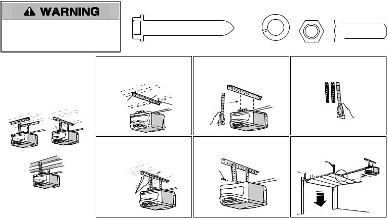
5 Hang the garage door opener
To avoid possible SERIOUS NJURY froma falling garage door opener,fasten itSECURELY to
structural supportsofthe garage.Concrete anchorsMUST be used ifinstalling ANY bracketsinto masonry.
|
|
|
|
|
|
|
|
|
|
|
|
|
|
|
|
|
|
|
|
|
|
|
|
|
|
|
HARDWARE |
|
|
|
|
|
|
|
|
|
|
|
|
|
|
|
|
|
|
|
|
|
|
|
|
|
|
|
|
H10 (2) |
|
|
|
|
|
|
|
|
|
H21 (2) |
|
H15 (2) |
|||||||||||||||||||||||||||||||||||||
|
|
|
|
|
|
|
|
|
|
|
|
H20 (2) |
|
|||||||||||||||||||||||||||||||||||||||
|
|
|
Lag Screw 5/16"- 18x1-7/8" |
|
|
|
|
|
|
|
|
Lock Washer |
Nut 5/16"-18 |
|
Hex Bolt 5/16"- 18x7/8" |
|||||||||||||||||||||||||||||||||||||
|
|
|
|
|
|
|
|
|
|
|
|
|
|
|
|
|
|
|
|
|
|
|
|
|
|
|
||||||||||||||||||||||||||
|
|
|
|
|
|
|
|
|
|
|
|
|
|
|
|
|
|
|
|
|
|
|
|
|
|
5/16"-18 |
|
|
|
|
|
|
|
|
|
|
|
|
|
|
|
|
|
|
|
|
|
|
|
|
|
|
|
|
|
|
|
|
|
|
|
|
|
|
|
|
|
|
|
|
|
|
|
|
|
|
|
|
|
|
|
|
|
|
|
|
|
|
|
|
|
|
|
|
|
|
|
|
|
|
|
|
|
||
|
|
|
|
|
|
|
|
|
|
|
|
|
|
|
|
|
|
|
|
|
|
|
|
|
|
|
|
|
|
|
|
|
|
|
|
|
|
|
|
|
|
|
|
|
|
|
|
|
|
|
|
|
|
|
|
|
|
|
|
|
|
|
|
|
|
|
|
|
|
|
|
|
|
|
|
|
|
|
|
|
|
|
|
|
|
|
|
|
|
|
|
|
|
|
|
|
|
|
|
|
|
|
|
|
|
|
|
|
|
|
|
|
|
|
|
|
|
|
|
|
|
|
|
|
|
|
|
|
|
|
|
|
|
|
|
|
|
|
|
|
|
|
|
|
|
|
|
|
|
|
|
|
|
|
|
|
|
|
|
|
|
|
|
|
|
|
|
|
|
|
|
|
|
|
|
|
|
|
|
|
|
|
|
|
|
|
|
|
|
|
|
|
|
|
|
|
|
|
|
|
|
|
|
|
|
|
|
|
|
|
|
|
|
|
|
|
|
|
|
|
|
|
|
|
|
|
|
|
|
|
|
|
|
|
|
|
|
|
|
|
|
|
|
|
|
|
|
|
|
|
|
|
|
|
|
|
|
|
|
|
|
|
|
|
Hanging the garage door opener will vary depending on your garage.Beloware three example installations.Your installation maybe different.For ALL installationsthe garage door opener MUSTbe connected to structural supports.The instructionsillustrate one ofthe examplesbelow.
Finished Ceiling
5.1On finished ceilings,use the lag screws (H10) to attach a supportbracket(not provided) to the structural supports before installing the garage door opener.
|
|
(not provided) |
|
Finished |
H10 |
|
|
Ceiling |
H10 |
||
|
|||
|
|
5.2Make sure the garage door opener is aligned with the header bracket.Measure the distance fromeach side ofthe garage door opener to the supportbracket.
5.3Cutboth piecesofthe hanging bracket (notprovided) to required lengths.
|
5.4 Attach the end ofeach hanging bracketto |
|
the supportbracketwith appropriate |
Unfinished Ceiling |
hardware (notprovided). |
(not provided)
5.5Attach the garage door opener to the hanging bracketswith the bolts(H21), lockwashers(H15) and nuts(H20).
H15
H21 


H20
5.6Remove the 2x4 and manuallyclose the door.Ifthe door hitsthe rail,raise the header bracket.
15
Loading...