


 Loading...
The Chamberlain Group, Inc. 845 Larch Avenue
Elmhurst, Illinois 60126-1196 www.liftmaster.com
12 VOLT DC SINGLE
SOLAR RESIDENTIAL GATE OPERATOR

 Models LA412 and LA412-S
For Residential Use Only
Owner’s Manual
■Please read this manual and the enclosed safety materials carefully!
■Periodic checks of the operator by a qualified technician are required to ensure safe operation.
■The model number label is located inside the control box of your operator.
■Serial #
■Installation Date

TABLE OF CONTENTS
2-7 INTRODUCTION
2Safety Symbol and Signal Word Review
3Operator Specifi cations
4-5 Safety Installation Information
6 Carton Inventory
6Hardware Inventory
7Additional Items for Purchase
7Tools Needed
8-12 PREPARATION AND OVERVIEW
8Single Gate Overview
9Dual Gate Overview
10Check Your Gate
11Mounting Options
12-21 INSTALLATION
12-18 Attach the Operator to the Gate
19-20 Mount the Control Box
21-22 WIRING
21-23 Connect Gate Operator (Gate 1) to Control Box 24-26 Connect Gate Operator (Gate 2) to Control Box
(Model LA412-S Only)
27-32 SOLAR PANEL INSTALLATION
27Select Site for Solar Panel(s)
28Overview of Solar Panel Installation
29Position Solar Panel(s)
30Position Solar Bracket
30 Insert Mounting Bolts
30Secure Solar Panel(s) to Solar Bracket
30Mount Solar Panel(s) Assembly
31Connect Solar Panel(s) to Operator Control Box
32Connect Batteries
33-36 PROGRAMMING
33-34 Program Limits
35Force and Timer To Close
36To Add or Reprogram a Remote Control
36 To Add a Wireless Keyless Entry
36 To Erase All Codes
37-43 OPERATION AND MAINTENANCE
37 Important Safety Information
37 Using Your Gate Operator
37 Manual Release
37 Maintenance
39Wiring Diagram
40Diagnostic Chart 41-43 Troubleshooting
INTRODUCTION
44-45 REPAIR PARTS
46ACCESSORIES
47WARRANTY
47 |
REPAIR PARTS AND SERVICE |
BACK |
TEMPLATE FOR POST BRACKET MOUNTING |
Safety Symbol and Signal Word Review
This gate operator has been designed and tested to offer safe service provided it is installed, operated, maintained and tested in strict accordance with the instructions and warnings contained in this manual.
 WARNING
Mechanical
 WARNING
Electrical
CAUTION
When you see these Safety Symbols and Signal Words on the following pages, they will alert you to the possibility of serious injury or death if you do not comply with the warnings that accompany them. The hazard may come from something mechanical or from electric shock. Read the warnings carefully.
When you see this Signal Word on the following pages, it will alert you to the possibility of damage to your gate and/or the gate operator if you do not comply with the cautionary statements that accompany it. Read them carefully.
IMPORTANT NOTE
• BEFORE attempting to install, operate or maintain the operator, you must read and fully understand this manual and follow all safety instructions.
• DO NOT attempt repair or service of your commercial door and gate operator unless you are an Authorized Service Technician.
Introduction |
2 |
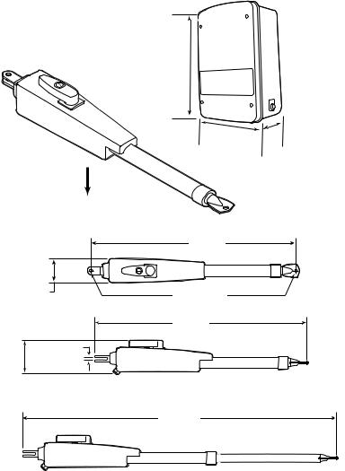
Operator Dimensions and Specifications
Main Supply |
12VDC Battery run. Operational between 11.5VDC and 14.5VDC. |
Accessory Power |
12V nominal Class II battery voltage source is limited to: |
|
• Solar or AC Cable up to 50' - 500 mA |
|
• AC Cable 50' up to 250' - 250mA |
|
• AC Cable 250' up to 1000' - 100mA |
|
NOTE: Increased accessory power drawn from the operator will shorten the |
|
battery life. |
Battery Charger Supply (Optional) |
14.5Vac nominal, 30 VA max. |
Maximum Gate Length and Weight |
16 ft. at 550 lbs. |
Temperature |
-20°C to +50°C (-4°F to 122°F) |
Protection Fuse Battery 1 |
ATC 20A |
Protection Fuse Battery 2 |
ATC 20A |
14" (35.6 cm)
10"
(25.4 cm) 6"
(15.2 cm)
Weight: 47 lbs. (21 kg)
36.3" (92.1 cm)
4.00" (10.2 cm)
.475" DIA. (1.2 cm DIA.)
37.4" (95.0 cm)
4.50" |
.250" |
(11.2 cm) |
(0.635 cm) |
53.5" (136.0 cm)
3 |
Introduction |
SAFETY INSTALLATION INFORMATION
1.READ and FOLLOW all instructions.
2.The gate operator is intended for use with Class I vehicular swing gates.
Class I denotes a vehicular gate operator (or system) intended for use in a home of one to four single family dwellings, or a garage or parking area associated therewith.
Install the gate operator only when the operator is appropriate for the construction and the usage class of the gate.
3.Gate operating system designers, installers and users must take into account the possible hazards associated with each individual application. Improperly designed, installed or maintained systems can create risks
for the user as well as the bystander. Gate system design and installation must reduce public exposure to potential hazards. Install the gate operator only when the operator is appropriate for the construction of the gate and the usage class of the gate. All exposed pinch points must be eliminated or guarded.
4.A gate operator can create high levels of force during normal operation. Therefore, safety features must be incorporated into every installation. Specifi c safety features include safety sensors.
5.The gate must be properly installed and work freely in both directions prior to the installation of the gate operator.
6.The gate must be installed in a location so that enough clearance is provided between the gate and adjacent structures when opening and closing to reduce the risk of entrapment. Swinging gates shall not open into public access areas.
7.The operator is intended for use only on gates used for vehicles. Pedestrians must be supplied with a separate access opening. The pedestrian access opening
shall be designed to promote pedestrian usage. The pedestrian access shall be located such that persons will not come in contact with the moving vehicular gate.
8.Pedestrians should never cross the pathway of a moving gate. The gate operator is not acceptable for use on any pedestrian gate. Pedestrians must be supplied with a separate pedestrian access.
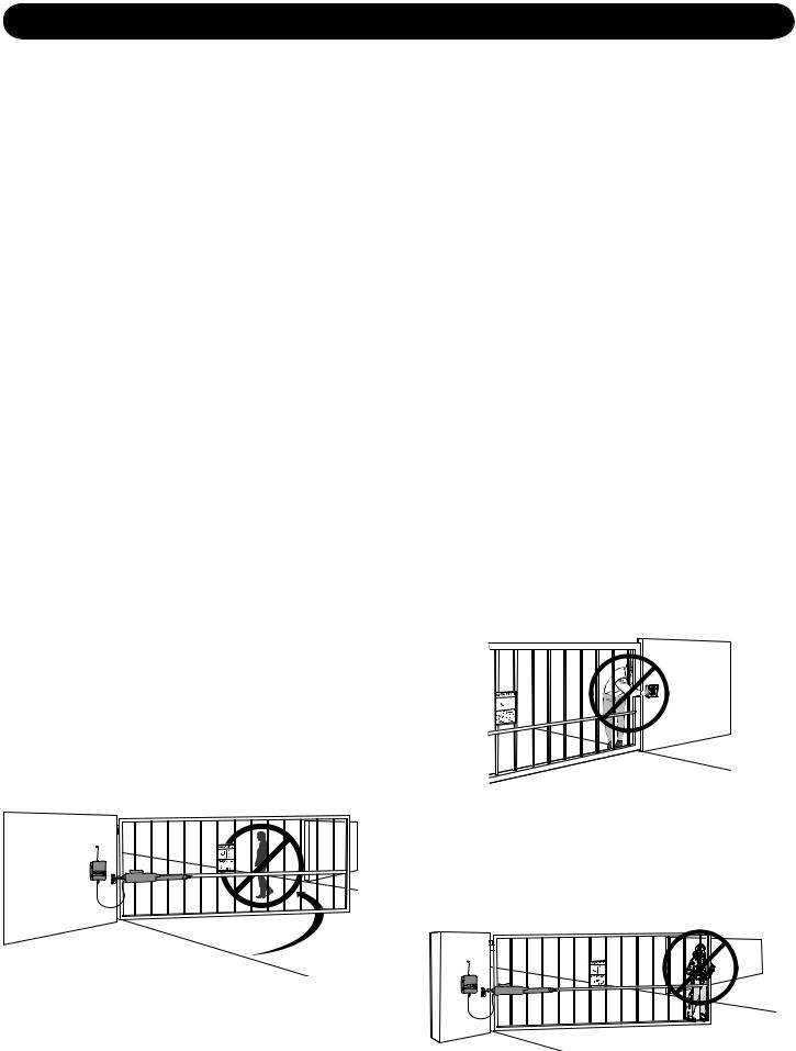
9.For an installation utilizing non-contact sensors (safety sensors), see product manual on the placement of non-contact sensors (safety sensors) for each type of application.
a.Care shall be exercised to reduce the risk of nuisance tripping, such as when a vehicle trips the safety sensor while the gate is still moving.
b.One or more non-contact sensors (safety sensors) shall be located where the risk of entrapment or obstruction exists, such as the perimeter reachable by a moving gate or barrier.
10. For a gate operator utilizing a contact sensor such as an edge sensor:
a.A hard wired contact sensor shall be located and its wiring arranged so the communication between the sensor and the gate operator is not subject to mechanical damage.
b.One or more contact sensors shall be located on the inside and outside leading edge of a swing gate. Additionally, if the bottom edge of a swing gate is greater than 6" (152 mm) above the ground at any point in its arc of travel, one or more contact sensors shall be located on the bottom edge.
11.Never mount any device that operates the gate operator where the user can reach over, under, around or through the gate to operate the controls. Controls are to be placed at least 6' (1.8 m) from any part of the moving gate:
•A hard wired control device shall be located and its wiring arranged so that communication between the control device and the gate operator is not subject to mechanical damage.
12.Controls intended to be used to reset an operator after 2 sequential activations of the entrapment protection device or devices must be located in the line of sight of the gate, or easily accessible controls shall have a security feature to prevent unauthorized use. Never allow anyone to hang on or ride the gate during the entire travel of the gate.
Introduction |
4 |
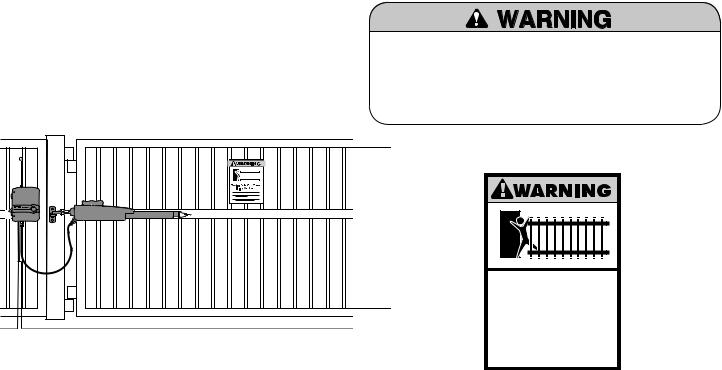
13.Each gate operator is provided with two safety warning placards. The placards are to be installed on the front and back of the gate where they are plainly visible. The placards may be mounted using cable ties through the four holes provided on each placard.
All warning signs and placards must be installed where visible in the area of the gate.
To prevent SERIOUS INJURY or DEATH from a moving gate:
•Install warning signs on the front and back of the gate in PLAIN VIEW.
•Permanently secure each warning sign in a suitable manner using fastening holes.
14.To AVOID damaging gas, power, or other underground utility lines, contact underground utility locating companies BEFORE digging.
15.SAVE THE INSTRUCTIONS.
Moving Gate Can Cause
Injury or Death
KEEP CLEAR! Gate may move at any time without prior warning.
Do not let children operate the gate or play in the gate area.
This entrance is for vehicles only. Pedestrians must use separate entrance
5 |
Introduction |
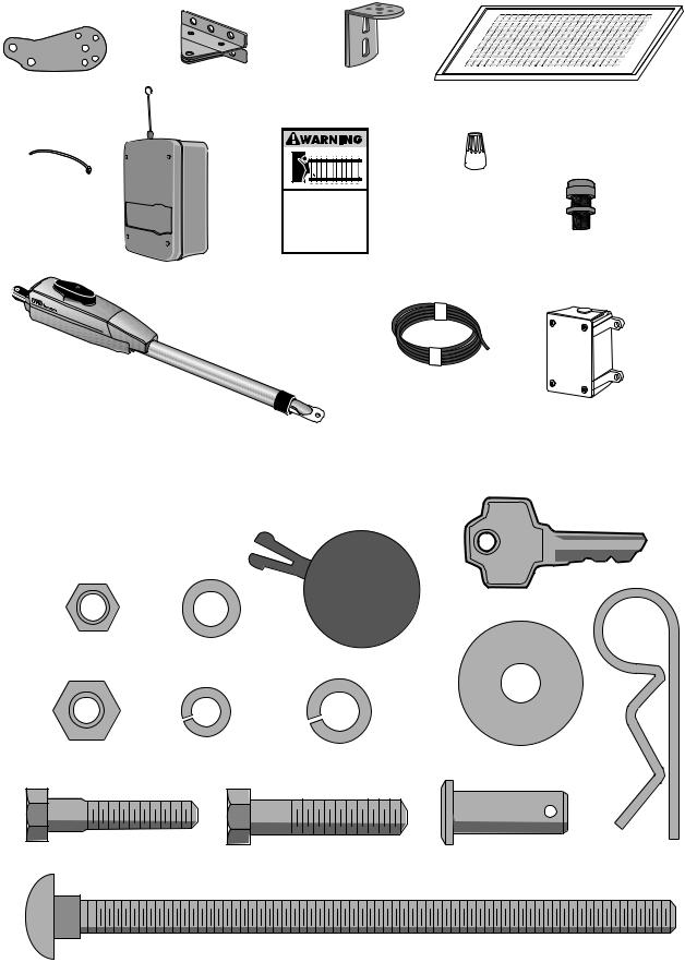
Carton Inventory
This operator comes with the hardware to install on a gate that pulls-to-open. If your application requires the gate to be pushed open, accessory kit 50-19503 is required.
Extension Bracket |
Gate Bracket |
Model LA412 (1) |
Model LA412 (1) |
Model LA412-S (2) |
Model LA412-S (2) |
Cable Ties (4)
Control Box (1) with 2 Batteries
Post Bracket
Model LA412 (1)
Model LA412-S (2)
Moving Gate Can Cause Injury or Death
KEEP CLEAR! Gate may move at any time without prior warning.
Do not let children operate the gate or play in the gate area.
This entrance is for vehicles only Pedestrians must use separate entrance
Warning Signs (2)
12V 10W Solar Panel
Model SOLPNL10W12V (1)
Wire Nuts (6)
Model LA412 ONLY
Watertight Connector
Model LA412-S ONLY (2)
Gate Operator |
Extension Cable |
|
Model LA412-S ONLY |
||
Model LA412 (1) |
||
|
||
Model LA412-S (2) |
Junction Box |
|
|
Model LA412-S ONLY |
Hardware Inventory
NOTE: Hardware quantities shown below are for LA412. Quantities are doubled for LA412-S.
Key (2)
Hex Nut 5/16"-18 (1) |
Flat Washer 5/16" (1) |
|
Cap |
Lock Washer 5/16" (1) |
Lock Washer 3/8" (3) |
|
|
Hex Nut 3/8"-16 (3) |
Flat Washer 3/8" (3) |
|
|
|
|
||
Hex Bolt 5/16"-18 x 1-1/2 (1) |
Hex Bolt |
Pin (2) |
|
|
Hairpin Clip (2) |
||
|
3/8"-16 x 1-1/2" (1) |
|
|
|
|
|
Carriage Bolt 3/8" x 5-15/16" (2)
Introduction |
6 |
 Additional Items For Purchase
The following items are REQUIRED to complete the installation:
ALL MODELS:

 SAFETY SENSORS
The Model 50-220 safety sensors are intended for installation with the operators covered in this manual.
To order call 1-800-528-2806 or visit www.liftmaster.com.

 HARDWARE
•5/16" mounting hardware for gate bracket.
•The following hardware is needed to mount the control box depending on the mounting surface:
Wood: Four #8 1-1/4" zinc plated wood screws.
Metal: Four #10-32x6" zinc plated machine screws with nut and lock washers.
Concrete, Brick, etc.: Four 1/4" x 1-3/4" masonry screws.
LA412-S ONLY:

 CONDUIT
UL Listed outdoor electrical conduit with 3/4" diameter to hold the extension cable between the junction box and the control box.
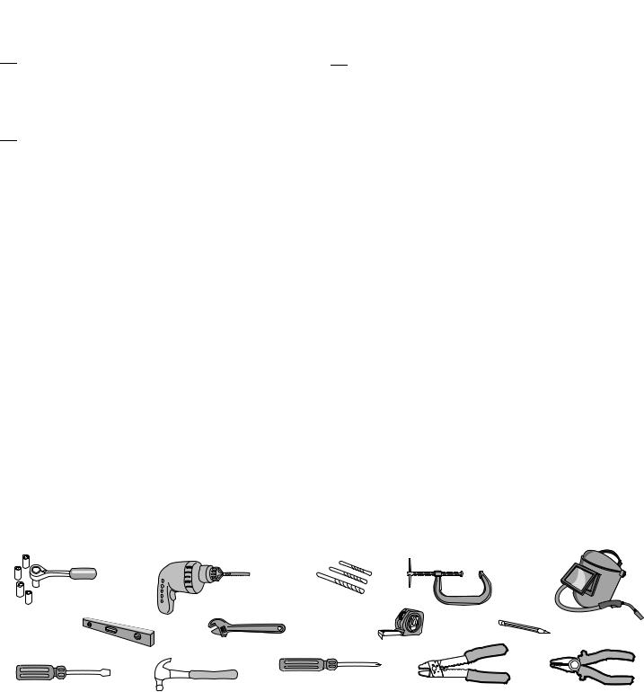
Tools Needed
During assembly, installation and adjustment of the operator, instructions will call for tools as illustrated below.
Deep Well Sockets |
|
Drill Bits |
|
|
and Wrench |
|
|
||
|
1/2", 3/16", 5/16" |
|
||
1/2", 5/8", 7/16", 9/16" |
Drill |
|
||
and 5/32" |
Clamps |
|||
and 1/4" |
|
|||
|
|
Welder (Optional)
1
2
|
Adjustable End Wrench |
Tape Measure |
Pencil |
Carpenter's Level |
|
||
|
|
||
|
|
|
|
Screwdriver |
Phillips Head Screwdriver |
|
|
Hammer |
Wire Strippers (Optional) |
Wire Cutters (Optional) |
|
|
|
7 |
Introduction |
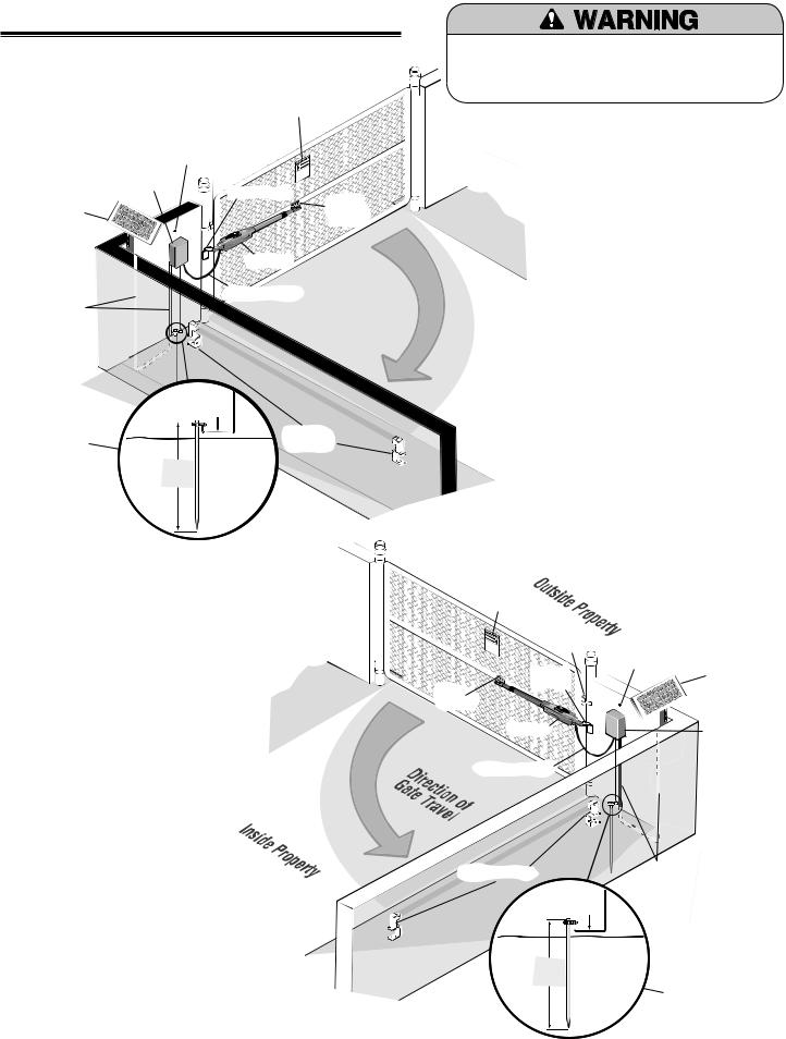
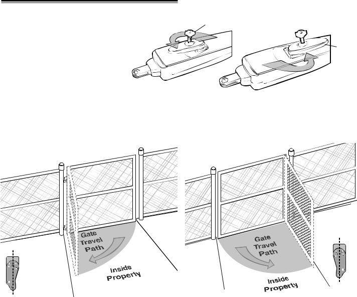
OVERVIEW OF TYPICAL INSTALLATION
LEFT-HAND GATE
|
|
|
|
|
Property |
Warning Sign |
||||
|
|
|
|
|
|
|||||
|
|
Outside |
|
|
|
|||||
|
Control Box |
|
Antenna |
|
||||||
|
|
|
|
|
|
|
Hinge |
|
||
|
with Batteries |
|
|
|||||||
|
|
|
|
|||||||
Solar Panel |
|
|
|
|
|
|
|
|
Post Bracket |
|
(facing South) |
|
|
|
|
|
|
|
|
|
Gate |
|
|
|
|
|
|
|
|
|
Bracket |
|
|
|
|
|
|
|
|
|
|
|
|
PVC Conduit (not |
|
|
|
|
|
|
|
|
|
Operator |
|
|
|
|
|
|
|
|
|
||
|
|
|
|
|
|
|
|
|
||
|
|
|
|
|
|
|
|
|
|
|
provided) to |
|
|
|
|
|
|
|
|
|
|
protect the power |
|
|
|
|
|
|
|
|
Operator Cable |
|
cable for solar and |
|
|
|
|
|
|
|
|
||
|
|
|
|
|
|
|
|
|
|
|
low voltage wire |
|
|
|
|
|
|
|
|
|
|
from lawn mowers |
|
|
|
|
|
|
|
|
|
|
and string |
|
|
|
|
|
|
|
|
|
|
trimmers. |
|
|
|
|
|
|
|
|
|
|
|
|
|
|
|
|
|
|
12 |
|
|
|
|
|
|
|
|
|
|
|
||
|
|
|
|
|
|
|
|
|
gauge |
|
|
|
|
|
|
|
|
|
|
wire |
|
Earth Ground |
|
|
|
|
|
|
|
|
|
Safety |
|
|
|
|
|
|
|
|
|
||
|
|
|
|
|
|
|
|
|
||
|
|
|
|
|
|
|
|
|
||
Installation |
|
|
|
|
|
|
|
|
|
|
|
|
|
|
|
|
|
|
|
Sensors |
|
(Optional) |
|
|
|
|
|
|
|
|
|
|
|
|
|
|
|
|
|
|
|
|
|
|
|
|
8 ft. |
|
|
|
||||
|
|
|
(2.4 m) |
|
|
|
||||
To prevent SERIOUS INJURY or DEATH; one or more shall be located where the risk of
obstruction exists.
Property
Inside
NOTE: One or more non-contact sensors shall be located where the risk of entrapment or obstruction exists at either the opening or closing direction. Care shall be exercised to reduce the risk of nuisance tripping, such as when a vehicle, trips the sensor while the gate is still moving.
Warning
Sign
Hinge
|
Post |
Antenna |
Solar Panel |
||
|
|
|
|||
|
|
|
(facing South) |
||
|
Bracket |
|
|
||
Gate |
|
|
|
||
|
|
|
|
|
|
Bracket |
Operator |
|
|
|
Control Box |
|
|
|
|
||
|
|
|
|
||
|
|
|
|
||
|
|
|
|
||
|
|
|
|
with Batteries |
|
|
|
|
|
|
|
|
Operator Cable |
|
|
|
|
Safety Sensors
12 gauge wire
8 ft.
(2.4 m)
PVC Conduit (not provided) to protect the power cable for solar and low voltage wire from lawn mowers and string trimmers.
Earth Ground Installation (Optional)
Preparation and Overview |
8 |
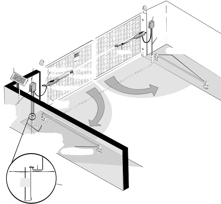
Dual Gate Typical Installation
Property
Outside
Warning Sign
Hinge
e Can |
Cause |
ng Gator Death |
|
MoviInjury |
|
Solar Panel
(facing South) Antenna
 Post Bracket


 Gate Bracket


 Gate 1


Junction Box
|
Extension Cable |
Gate 2 |
Safety Sensors |
|
Gate
Control Box with Batteries


 Operator
Cable
|
of |
|
ravel |
Direction |
|
T |
|
1 |
|
Gate |
|
Property
Inside
PVC Conduit (not provided) to |
|
||||
protect the power cable for |
|
||||
solar and low voltage wire |
|
||||
from lawn mowers and string |
|
||||
trimmers. |
Safety Sensors |
||||
12 |
|
||||
|
|
|
|
gauge |
|
|
|
|
|
wire |
|
|
|
|
|
|
|
|
|
|
|
|
|
|
|
|
|
|
|
8 ft.
(2.4 m) Earth Ground Installation (Optional)
NOTE: One or more non-contact sensors shall be located where the risk of entrapment or obstruction exists at either the opening or closing direction. Care shall be exercised to reduce the risk of nuisance tripping, such as when a vehicle, trips the sensor while the gate is still moving.
9 |
Preparation and Overview |
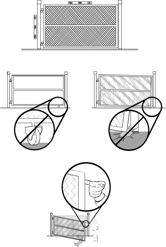
Check Your Gate
Gate MUST be level.
and gate post MUST |
be plumb. |
Gate |
|
Remove ANY/ALL wheels from the bottom of gate.
Gate MUST NOT hit or drag across ground.
Gate MUST swing freely and be supported entirely by its hinges.
Preparation and Overview |
10 |
Mounting Options
Mounting locations vary depending on the type and style of your gate.
NOTES:
•The top of the operator must be mounted at least 10 inches above the ground. Environmental conditions should be considered at this time.
•The operator is not recommended for plastic or vinyl gates. Contact the gate’s manufacturer for recommendations and options.
Recommended:
= Gate post bracket mounting locations
= Gate bracket mount locations
|
|
|
LEFT-HAND HINGE MOUNTED |
|
|
|
|
|
RIGHT-HAND HINGE MOUNTED |
|
|
|
|||||||||
|
|
|
|
|
|
|
|
|
|
|
|
|
|
|
|
|
|
|
|
|
|
|
|
|
|
|
|
|
|
|
|
|
|
|
|
|
|
|
|
|
|
|
|
|
|
|
|
|
|
|
|
|
|
|
|
|
|
|
|
|
|
|
|
|
|
|
|
|
|
|
|
|
|
|
|
|
|
|
|
|
|
|
|
|
|
|
|
|
|
|
|
|
|
|
|
|
|
|
|
|
|
|
|
|
|
|
|
|
|
|
|
|
|
|
|
|
|
|
|
|
|
|
|
|
|
|
|
|
|
|
|
|
|
|
|
|
|
|
|
|
|
|
|
|
|
|
|
|
|
|
|
|
|
|
|
|
|
|
|
|
|
|
|
|
|
|
|
|
|
|
|
|
|
|
|
|
|
|
|
|
|
|
|
|
|
|
|
|
|
|
|
|
|
|
|
|
|
|
|
|
|
|
|
|
|
|
|
|
|
|
|
|
|
|
|
|
|
|
|
|
|
|
|
|
|
|
|
|
|
|
|
|
|
|
|
|
|
|
|
|
|
Typical Chain-Link Gate
Typical Chain-Link Gate
|
|
|
|
|
|
|
|
|
|
|
|
|
|
|
|
|
|
|
|
|
|
|
|
|
|
|
|
|
|
|
|
|
|
|
|
|
|
|
|
|
|
|
|
|
|
|
|
|
|
|
|
|
|
|
|
|
|
|
|
|
|
|
|
|
|
|
|
|
|
|
|
|
|
|
|
|
|
|
|
|
|
|
|
|
|
|
|
|
|
|
|
|
|
|
|
|
|
|
|
|
|
|
|
|
|
|
|
|
|
|
|
|
|
|
|
|
|
|
|
|
|
|
|
|
|
|
|
|
|
|
|
|
|
|
|
|
|
|
|
|
|
|
|
|
|
|
|
|
|
|
|
|
|
|
|
|
|
|
|
|
|
|
|
|
|
|
|
|
|
|
|
|
|
|
|
|
|
|
|
|
|
|
|
|
|
|
|
|
|
|
|
|
|
|
|
|
|
|
|
|
|
|
|
|
|
|
|
|
|
|
|
|
|
|
|
|
|
|
|
|
|
|
|
|
|
|
|
|
|
|
|
|
|
|
|
|
|
|
|
|
|
|
|
|
|
|
|
|
|
|
|
|
|
|
|
|
|
|
|
|
|
|
|
|
|
|
|
|
|
|
|
|
|
|
|
|
|
|
|
|
|
|
|
|
|
|
|
|
|
|
|
|
|
|
|
|
|
|
|
|
|
|
|
|
|
|
|
|
|
|
|
|
|
|
|
|
|
|
|
|
|
|
|
|
|
|
|
|
|
|
|
|
|
|
|
|
|
|
|
|
|
|
|
|
|
|
|
|
|
|
|
|
|
|
|
|
|
|
|
|
|
|
|
|
|
|
|
|
|
|
|
|
|
|
|
|
|
|
|
|
|
|
|
|
|
|
|
|
|
|
|
|
|
|
|
|
|
|
|
|
|
|
|
|
|
|
|
|
|
|
|
|
|
|
|
|
|
|
|
|
|
|
|
|
|
|
|
|
|
|
|
|
|
|
|
|
|
|
|
|
|
|
|
|
|
|
|
|
|
|
|
|
|
|
|
|
|
|
|
|
|
|
|
|
|
|
|
|
|
|
|
|
|
|
|
|
|
|
|
|
|
|
|
|
|
|
|
|
|
|
|
|
|
|
|
|
|
|
|
|
|
|
|
|
|
|
|
|
|
|
|
|
|
|
|
|
|
|
|
|
|
|
|
|
|
|
|
|
|
|
|
|
|
|
|
|
|
|
|
|
|
|
|
|
|
|
|
|
|
|
|
|
|
|
|
|
|
|
|
|
|
|
|
|
|
|
|
|
|
|
|
|
|
|
|
|
|
|
|
|
|
|
|
|
|
|
|
|
|
|
|
|
|
|
|
|
|
|
|
|
|
|
|
|
|
|
|
|
|
|
|
|
|
|
|
|
|
|
|
|
|
|
|
|
|
|
|
|
|
|
|
|
|
|
|
|
|
|
|
|
|
|
|
|
|
|
|
|
|
|
|
|
|
|
|
|
|
|
|
|
|
|
|
|
|
|
|
|
|
|
|
|
|
|
|
|
|
|
|
|
|
|
|
|
|
|
|
|
|
|
|
|
|
|
|
|
|
|
|
|
|
|
|
|
|
|
|
|
|
|
|
|
|
|
|
|
|
|
|
|
|
|
|
|
|
|
|
|
|
|
|
|
|
|
|
|
|
|
|
|
|
|
|
|
|
|
|
|
|
|
|
|
|
|
|
|
|
|
|
|
|
|
|
|
|
|
|
|
|
|
|
|
|
|
|
|
|
|
|
|
|
|
|
|
|
Typical Farm/Ranch Gate |
|
|
|
|
|
|
|
|
|
|
|
|
Typical Farm/Ranch Gate |
|
|
|
|||||||||||||||||||||||||||||||||||||||||||||||||||||||||
|
|
|
|
|
|
|
|
|
|
|
|
|
|
|
|
|
|
|
|
|
|
|
|
|
|
|
|
|
|
|
|
|
|
|
|
|
|
|
|
|
|
|
|
|
|
|
|
|
|
|
|
|
|
|
|
|
|
|
|
|
|
|
|
|
|
|
|
|
|
|
|
|
|
|
|
|
|
|
|
|
|
|
|
|
|
|
|
|
|
|
|
|
|
|
|
|
|
|
|
|
|
|
|
|
|
|
|
|
|
|
|
|
|
|
|
|
|
|
|
|
|
|
|
|
|
|
|
|
|
|
|
|
|
|
|
|
|
|
|
|
|
|
|
|
|
|
|
|
|
|
|
|
|
|
|
|
|
|
|
|
|
|
|
|
|
|
|
|
|
|
|
|
|
|
|
|
|
|
|
|
|
|
|
|
|
|
|
|
|
|
|
|
|
|
|
|
|
|
|
|
|
|
|
|
|
|
|
|
|
|
|
|
|
|
|
|
|
|
|
|
|
|
|
|
|
|
|
|
|
|
|
|
|
|
|
|
|
|
|
|
|
|
|
|
|
|
|
|
|
|
|
|
|
|
|
|
|
|
|
|
|
|
|
|
|
|
|
|
|
|
|
|
|
|
|
|
|
|
|
|
|
|
|
|
|
|
|
|
|
|
|
|
|
|
|
|
|
|
|
|
|
|
|
|
|
|
|
|
|
|
|
|
|
|
|
|
|
|
|
|
|
|
|
|
|
|
|
|
|
|
|
|
|
|
|
|
|
|
|
|
|
|
|
|
|
|
|
|
|
|
|
|
|
|
|
|
|
|
|
|
|
|
|
|
|
|
|
|
|
|
|
|
|
|
|
|
|
|
|
|
|
|
|
|
|
|
|
|
|
|
|
|
|
|
|
|
|
|
|
|
|
|
|
|
|
|
|
|
|
|
|
|
|
|
|
|
|
|
|
|
|
|
|
|
|
|
|
|
|
|
|
|
|
|
|
|
|
|
|
|
|
|
|
|
|
|
|
|
|
|
|
|
|
|
|
|
|
|
|
|
|
|
|
|
|
|
|
|
|
|
|
|
|
|
|
|
|
|
|
|
|
|
|
|
|
|
|
|
|
|
|
|
|
|
|
|
|
|
|
|
|
|
|
|
|
|
|
|
|
|
|
|
|
|
|
|
|
|
|
|
|
|
|
|
|
|
|
|
|
|
|
|
|
|
|
|
|
|
|
|
|
|
|
|
|
|
|
|
|
|
|
|
|
|
|
|
|
|
|
|
|
|
|
|
|
|
|
|
|
|
|
|
|
|
|
|
|
|
|
|
|
|
|
|
|
|
|
|
|
|
|
|
|
|
|
|
|
|
|
|
|
|
|
|
|
|
|
|
|
|
|
|
|
|
|
|
|
|
|
|
|
|
|
|
|
|
|
|
|
|
|
|
|
|
|
|
|
|
|
|
|
|
|
|
|
|
|
|
|
|
|
|
|
|
|
|
|
|
|
|
|
|
|
|
|
|
|
|
|
|
|
|
|
|
|
|
|
|
|
|
|
|
|
|
|
|
|
|
|
|
|
|
|
|
|
|
|
|
|
|
|
|
|
|
|
|
|
|
|
|
|
|
|
|
|
|
|
|
|
|
|
|
|
|
|
|
|
|
|
|
|
|
|
|
|
|
|
|
|
|
|
|
|
|
|
|
|
|
|
|
|
|
|
|
|
|
|
|
|
|
|
|
|
|
|
|
|
|
|
|
|
|
|
|
|
|
|
|
|
|
|
|
|
|
|
|
|
|
|
|
Typical Wood Gate |
|
|
|
|
|
|
|
|
|
|
|
|
|
|
|
|
|
|
|
|
|
|
|
Typical Wood Gate |
|||||||||||||||||||||||||||||||||||||||||||||||||||||||||||||||
|
|
|
|
|
|
|
|
|
|
|
|
|
|
|
|
|
|
|
|
|
|
|
|
|
|
|
|
|
|
|
|
|
|
|
|
|
|
|
|
|
|
|
|
|
|
|
|
|
|
|
|
|
|
|
|
|
|
|
|
|
|
|
|
|
|
|
|
|
|
|
|
|
|
|
|
|
|
|
|
|
|
|
|
|
|
|
|
|
|
|
|
|
|
|
|
|
|
|
|
|
|
|
|
|
|
|
|
|
|
|
|
|
|
|
|
|
|
|
|
|
|
|
|
|
|
|
|
|
|
|
|
|
|
|
|
|
|
|
|
|
|
|
|
|
|
|
|
|
|
|
|
|
|
|
|
|
|
|
|
|
|
|
|
|
|
|
|
|
|
|
|
|
|
|
|
|
|
|
|
|
|
|
|
|
|
|
|
|
|
|
|
|
|
|
|
|
|
|
|
|
|
|
|
|
|
|
|
|
|
|
|
|
|
|
|
|
|
|
|
|
|
|
|
|
|
|
|
|
|
|
|
|
|
|
|
|
|
|
|
|
|
|
|
|
|
|
|
|
|
|
|
|
|
|
|
|
|
|
|
|
|
|
|
|
|
|
|
|
|
|
|
|
|
|
|
|
|
|
|
|
|
|
|
|
|
|
|
|
|
|
|
|
|
|
|
|
|
|
|
|
|
|
|
|
|
|
|
|
|
|
|
|
|
|
|
|
|
|
|
|
|
|
|
|
|
|
|
|
|
|
|
|
|
|
|
|
|
|
|
|
|
|
|
|
|
|
|
|
|
|
|
|
|
|
|
|
|
|
|
|
|
|
|
|
|
|
|
|
|
|
|
|
|
|
|
|
|
|
|
|
|
|
|
|
|
|
|
|
|
|
|
|
|
|
|
|
|
|
|
|
|
|
|
|
|
|
|
|
|
|
|
|
|
|
|
|
|
|
|
|
|
|
|
|
|
|
|
|
|
|
|
|
|
|
|
|
|
|
|
|
|
|
|
|
|
|
|
|
|
|
|
|
|
|
|
|
|
|
|
|
|
|
|
|
|
|
|
|
|
|
|
|
|
|
|
|
|
|
|
|
|
|
|
|
|
|
|
|
|
|
|
|
|
|
|
|
|
|
|
|
|
|
|
|
|
|
|
|
|
|
|
|
|
|
|
|
|
|
|
|
|
|
|
|
|
|
|
|
|
|
|
|
|
|
|
|
|
|
|
|
|
|
|
|
|
|
|
|
|
|
|
|
|
|
|
|
|
|
|
|
|
|
|
|
|
|
|
|
|
|
|
|
|
|
|
|
|
|
|
|
|
|
|
|
|
|
|
|
|
|
|
|
|
|
|
|
|
|
|
|
|
|
|
|
|
|
|
|
|
|
|
|
|
|
|
|
|
|
|
|
|
|
|
|
|
|
|
|
|
|
|
|
|
|
|
|
|
|
|
|
|
|
|
|
|
|
|
|
|
|
|
|
|
|
|
|
|
|
|
|
|
|
|
|
|
|
|
|
|
|
|
|
|
|
|
|
|
|
|
|
|
|
|
|
|
|
|
|
|
|
|
|
|
|
|
|
|
|
|
|
|
|
|
|
|
|
|
|
|
|
|
|
|
|
|
|
|
|
|
|
|
|
|
|
|
|
|
|
|
|
|
|
|
|
Typical Tubular Metal Gate |
Typical Tubular Metal Gate |
11 |
Preparation and Overview |
INSTALLATION
MANUAL RELEASE |
Key |
Insert the key into the lock and turn it 180° |
|
1 counterclockwise. Turn the release lever |
|
180° counterclockwise. The operator is |
Release |
now in manual mode. |
Lever |
2 DETERMINE THE POSITION OF THE EXTENSION BRACKET
The extension bracket can be assembled to work on a Left-Hand or a Right-Hand gate. Review the gate types below and select the type of installation required.
NOTE: If the extension bracket is not assembled correctly damage to the operator may result.
Left-Hand Gate |
Right-Hand Gate |
Right-Hand
Gate
Left-Hand Gate
IMPORTANT NOTE: For Push to Open installation purchase kit 50-19503, see accessories.
Installation |
12 |
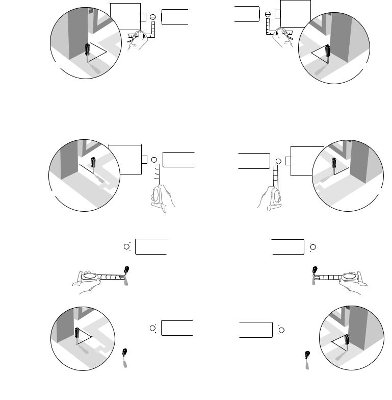
3 MEASURING AND MARKING FOR THE GATE BRACKET
Before proceeding, begin with the gate in the fully closed position. There are two methods for determining the proper location of the post brackets:
•Paper template (located on the back page of this manual. Must be cut out.)
•Tape measure.
Either method will work depending on preference.
NOTE: Be sure gate is in the closed position before proceeding.
Template Method
Place the template (provided on the back page) under the gate hinge point. Use a screwdriver or dowel rod to temporarily mark the location in front of the gate post.
LEFT SIDE BRACKET MOUNTING
Gate Post
Gate Hinge Point
TOP VIEW
Gate Post
Use a screwdriver or dowel rod to temporarily mark measurement.
Tape Measure Method
RIGHT SIDE BRACKET MOUNTING
Gate Post
Gate Hinge Point
TOP VIEW
Gate Post
Use a screwdriver or dowel rod to temporarily mark measurement.
Place the measuring tape under the gate hinge point and measure 7". Use a screwdriver or dowel rod to temporarily mark the location of the first measurement.
LEFT SIDE BRACKET MOUNTING
Gate Post
Gate Hinge Point
7" X

Gate Post
RIGHT SIDE BRACKET MOUNTING
Gate Post
Gate Hinge Point

 X 7"
X 7"
Gate Post
Measure 7" from the previous mark.
Gate Post |
|
|
|
Gate Post |
|||
|
Gate Hinge Point |
Gate Hinge Point |
|
||||
|
|
||||||
|
|
|
|
|
|
|
|
|
|
|
|
|
|
|
|
|
|
|
|
|
|
|
|
X 7"
7"
X
Use the screwdriver or dowel rod to mark the location of the second measurement.
Gate Post |
|
Gate Hinge Point |
|
|
|
Gate Post |
|
|
|
|
|
|
|||
|
|
|
|
Gate Hinge Point |
|
||
|
|
|
|
|
|
|
|
|
|
|
|
|
|
|
|
|
|
|
|
|
|
|
|
|
|
|
|
|
|
|
|
|
|
|
|
|
|
|
|
X First Marking
First Marking
X
13 |
Installation |
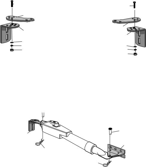
POSITION THE EXTENSION BRACKET TO POST BRACKET
Assemble the post bracket by placing the extension bracket on top of post bracket. Insert the bolt through |
||
4 the brackets and fasten them using the washer, lock washer and nut. DO NOT TIGHTEN AT THIS TIME. |
||
LEFT-HAND GATE |
RIGHT-HAND GATE |
|
Hex Bolt 3/8" |
Hex Bolt 3/8" |
|
|
||
Extension |
|
|
Bracket |
|
|
|
Extension |
|
Post Bracket |
Bracket |
|
|
||
|
Post Bracket |
|
Washer |
|
|
Lock Washer |
Washer |
|
Lock Washer |
||
Nut |
||
Nut |
||
|
||
NOTE: All the illustrations on the following pages display a typical Left-Hand Gate installation.
5 ATTACH BRACKETS TO GATE OPERATOR
Attach post bracket and gate bracket to operator using pins and hairpin clips.

 Pin
Pin
Pin
Post Bracket
Gate
Bracket
Hairpin
Clip
Hairpin
Clip
Installation |
14 |

6POSITION GATE OPERATOR ON GATE
The post bracket assembly can be mounted several places on the gate post. Refer to page 11 for mounting options. Place the operator arm against gate post at the desired vertical position and temporarily secure post bracket with a clamp. The gate operator (arm) must be level.
Open the gate to desired open position (no greater than 100°) and hold operator against gate. Mark mounting holes on gate for reference. Temporarily secure the gate bracket using a clamp.
For push to open installations refer to instructions with push to open kit 50-19503.
7 Hold the post bracket in the desired position. Align the extension bracket to a position as CLOSE AS POSSIBLE above the marker. Insert hex bolt through extension bracket and post bracket and secure with washer, lock washer and nut.
Hex Bolt 3/8"
Washer |
Lock Washer |
Nut |
15 |
Installation |
Loading...