


 Loading...
TM |
® |
|
Garage Door Opener
Owner’s Manual
Model 1000SDC-R |
|
Model 2000SDC-R |
1/3 HP |
|
1/2 HP |
|
|
|
For Residential Use Only
■Please read this manual and the enclosed safety materials carefully!
■Fasten the manual near the garage door after installation.
■The door WILL NOT CLOSE unless the Protector System® is connected properly aligned.
■Periodic checks of the opener are required to ensure safe operation.
■The model number label is located on the back of your opener.

Contents
Safety alert symbol review ........................................... |
2 |
Safety information and precautions .............................. |
3 |
Testing your garage door for binding & balance .......... |
3 |
Hardware supplied ........................................................ |
3 |
Carton inventory ........................................................... |
4 |
Illustration of sectional door installation ..................... |
5 |
Illustration of one-piece door installation ..................... |
5 |
Assembly section - pages 6 – 7 |
|
Fasten rail to power unit ............................................. |
6 |
Install the trolley ......................................................... |
6 |
Attach the rail brackets ............................................... |
7 |
Installation safety instructions .................................... |
7 |
Installation section - pages 8 – 23 |
|
Determine the header bracket location |
|
Sectional door ........................................................... |
8 |
One-piece door.......................................................... |
9 |
Install the header bracket .......................................... |
10 |
Attach the rail to the header bracket ......................... |
11 |
The Protector System® ............................................. |
12 |
Install the safety reversing sensor ............................. |
13 |
Position the opener.................................................... |
15 |
Hang the opener ........................................................ |
16 |
Install the door control and connect all wires ........... |
17 |
Electrical requirements ............................................. |
18 |
Complete the safety reversing sensor installation..... |
18 |
Install the lights and lens .......................................... |
19 |
Attach the manual release rope and handle............... |
19 |
Fasten the door bracket (sectional door)................... |
20 |
Fasten the door bracket (one-piece door).................. |
21 |
Connect door arm to trolley (sectional door)............ |
22 |
Connect door arm to trolley (one-piece door)........... |
23 |
Adjustment section - pages 24 – 26 |
|
Travel limit adjustments............................................ |
24 |
Force adjustments ..................................................... |
25 |
Test the Protector System® ........................................ |
26 |
Test the safety reverse system .................................. |
26 |
Operation safety instructions ...................................... |
27 |
Care of your opener .................................................... |
27 |
Maintenance schedule................................................. |
27 |
Operation of your opener ............................................ |
28 |
Receiver & remote control programming ................... |
29 |
Having a problem?...................................................... |
30 |
Repair parts, rail assembly.......................................... |
32 |
Repair parts, installation ............................................. |
32 |
Repair parts, power unit.............................................. |
33 |
Accessories ................................................................. |
34 |
Index ........................................................................... |
35 |
How to order repair parts ............................................ |
36 |
Warranty...................................................................... |
36 |
Start by reviewing these important safety alert symbols:
When you see these Safety Symbols on the following pages, they will alert you to the possibility of serious injury or death if you do not comply with the corresponding instructions. The hazard may come from something mechanical or from electric shock. Read the instructions carefully.
|
|
|
|
|
|
Mechanical |
|
Electrical |
|
|
|
When you see this Safety Symbol on the following pages, it will alert you to the possibility of damage to your garage door and/or the garage door opener if you do not comply with the corresponding instructions. Read the instructions carefully.
This garage door opener is designed and tested to offer safe service provided it is installed, operated, maintained and tested in strict accordance with the safety instructions contained in this manual.
2
Safety Information and Precautions
 WARNING
An unbalanced garage door might not reverse when required and someone under the door could be seriously injured or killed.
If your garage door binds, sticks or is out of balance, call for professional garage door service. Garage doors, door springs, cables, pulleys, brackets, and their hardware are under extreme tension and can cause serious injury or death. Do not try to loosen, move or adjust them yourself!
Ropes left on a garage door could cause someone to become entangled and killed. Remove all ropes connected to the door before installing and operating the opener.
Identify the type and height of your door, any special conditions that exist, and any additional materials that may be required.
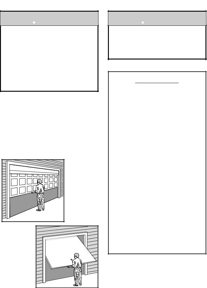
Test Your Door for Balance
Before you begin, complete the following test to make sure your door is balanced, and is not sticking or binding:
•Lift the door about halfway as shown. Release the door. It should stay in place, supported entirely by its springs.
•Raise and lower the door to see if there is any binding or sticking.
Sectional
Door
SECTIONAL DOOR
One-Piece
Door
ONE-PIECE DOOR
 CAUTION
To avoid damage to the garage door and opener, disable locks before installing and operating the opener. Use a wood screw or nail to hold locks in the "open" (unlocked) position.
Operation at other than 120V 60 Hz will cause opener malfunction and damage.
Hardware Supplied
Rail Assembly
Coupling Sleeve (1)
Hex Screw 1/4"-20 x 5/8" (4)
Nut 1/4" - 20 (4)
Opener Installation
Hex Screw 5/16"-18 x 7/8" (4)
Lag Screw 5/16"-9 x 1-5/8" (2)
Lag Screw 5/16"-18 x 1-7/8" (2)
Carriage Bolt 5/16"-18 x 2-1/2" (2)
Clevis Pin 5/16" x 2-3/4" (1)
Clevis Pin 5/16" x 1-1/4" (1)
Clevis Pin 5/16" x 1" (1)
Nut 5/16" - 18 (6)
Lock Washer 5/16" (6)
Screw 6AB x 1-1/4" (2)
Screw 6-32 x 1" (2)
Insulated Staples (10)
Ring Fastener (3)
Handle
Dry Wall Anchors (2)
Rope
Safety Reversing Sensor
Installation
Carriage Bolts 1/4" - 20 x 1/2" (2)
Wing Nut (2)
Insulated Staples (20)
3
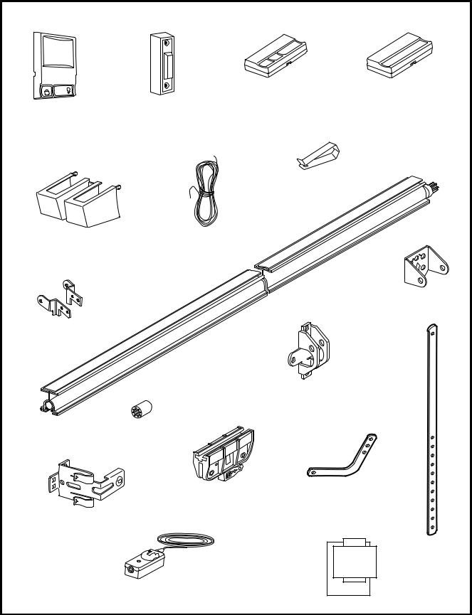
Carton Inventory
Your garage door opener is packaged in two cartons which contain the power unit and all parts illustrated below. Accessories will depend on model purchased. If anything is missing, carefully check the packing material. Parts may be "stuck" in the foam. KEEP THE FOAM INTACT (see page 6). Hardware is listed on page 3.
Model 2000SDC-R |
Model 1000SDC-R |
Model 2000SDC-R |
Model 1000SDC-R |
LOCK
LIGHT
Multi-Function |
Lighted |
Door Control Panel |
Door Control Button |
SECURITY |
SECURITY |
3-Channel Remote Control |
Single-Function Remote Control |
Remote Control
Transmitter Visor Clip
Light Lens |
2-Conductor Bell Wire |
|
White & White/Red |
Rail Brackets
Rail
Assembly
Door Bracket
Sprocket Coupling
Trolley
Curved Door
Arm Section
Safety Sensor
Bracket (2)
|
Safety Labels |
(2) Safety Reversing Sensors |
and |
(1 Sending Eye and 1 Receiving Eye) |
Literature |
with |
|
2-Conductor White & White/Black Bell Wire |
|
attached |
|
ONLY
MOUNT
CEILING
UP
Header Bracket
Straight Door
Arm Section
4

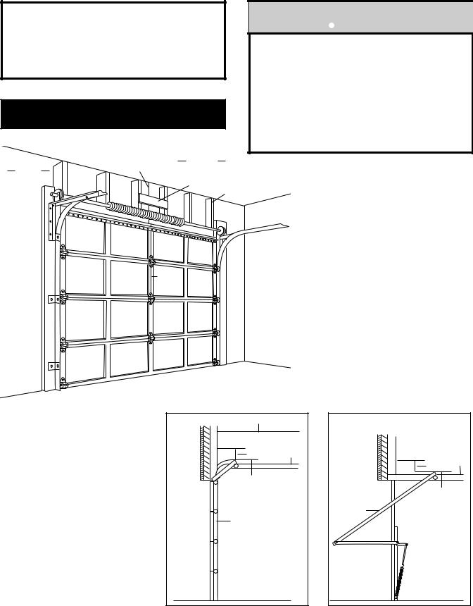
Before you begin, survey your garage area to see whether any of the conditions below apply to your installation. You may find it helpful to refer back to this page as you proceed with the installation of your opener.
SECTIONAL Door or ONE-PIECE Door with Track Installation
Horizontal and vertical reinforcement is needed for lightweight garage doors
(fiberglass, steel, aluminum, door with glass panels, etc.). See page 20 for details.
Header Wall
FINISHED CEILING Support bracket & fastening hardware is required.
See page 16.
Extension Spring
OR |
OR |
|
Torsion Spring |
One-Piece Door-Extension Spring |
|
|
||
— — |
Header |
|
Wall |
||
— |
|
|
Door Center |
Access Door |
|
— — — |
||
Track |
||
|
||
— — |
Door |
|
|
||
Safety |
|
|
Reversing |
|
|
Sensor |
|
|
Floor must be level |
|
|
across width of door |
|
|
Safety Reversing Sensor |
|
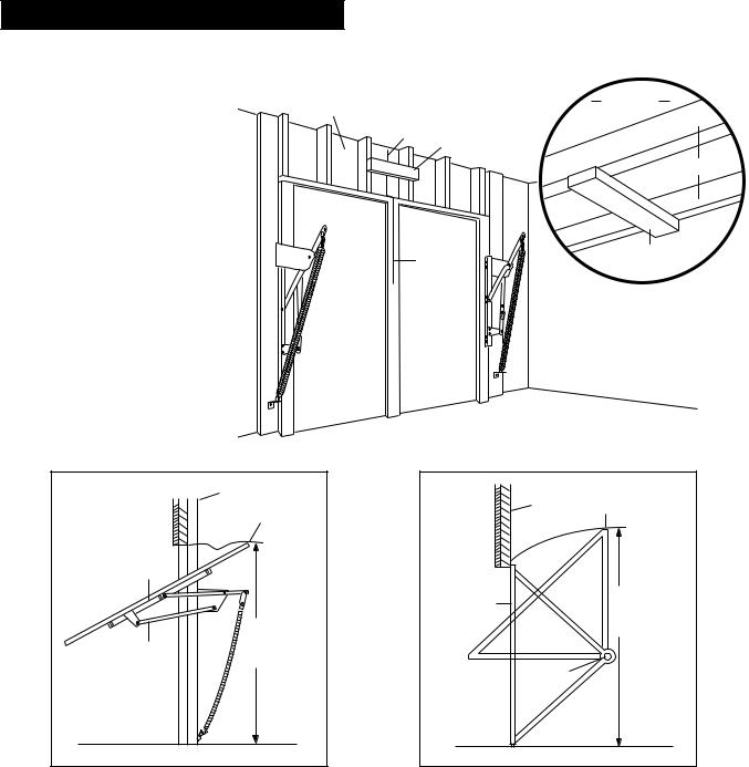
ONE-PIECE Door Without Track Installation
FINISHED CEILING Support bracket & fastening hardware is required. See page 16.
Header
Wall
Access Door
Safety Reversing
Sensor
Gap between floor and bottom of
door must not exceed 1/4".
Safety Reversing Sensor
5
Assembly Section: Pages 6 - 7
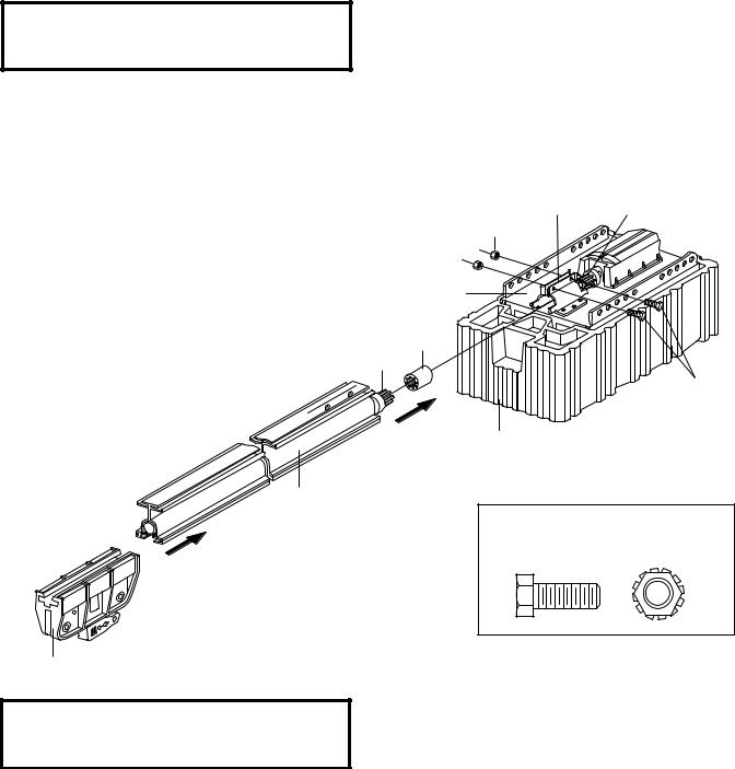
ASSEMBLY STEP 1
Fasten the Rail To the Power Unit
NOTE: To aid in assembly and installation, replace the foam packing around the power unit. Remove it after Installation Step 5.
•Working on a level surface, align the rail assembly with the power unit, as shown.
•Slip the coupling over the rail sprocket.
•Slide the rail through the power unit bracket until the coupling fits securely over the power unit sprocket.
•Align the two screw holes in the rail with those in the power unit bracket. Insert two 1/4"-20x5/8" hex screws and lock nuts. Tighten securely with a 7/16" socket wrench.
Rail
Assembly
Trolley
Rail/Power Unit |
Power Unit |
Bracket |
Sprocket |
Lock Nuts
1/4"-20
Opener
Chassis
Coupling
Rail
Sprocket
Hex Screws 1/4"-20x5/8"
Foam Packaging
Hardware Shown Actual Size
1/4" - 20 1/4" - 20 x 5/8" Lock Nut
Hex Screw
ASSEMBLY STEP 2
Install the Trolley
As illustrated above, slide the trolley onto and along the bottom of the rail until it snaps firmly in place. Be certain to install it facing correctly: the trolley release arm must be horizontal (lock position), with its arrow pointed away from the power unit.
6
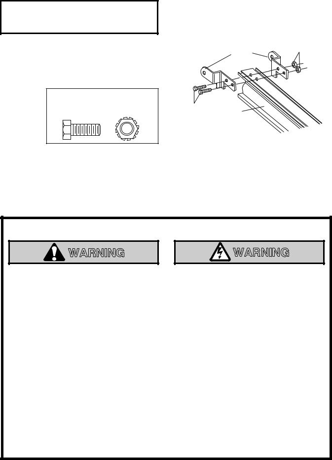
ASSEMBLY STEP 3
Attach the Rail Brackets
•Align rail brackets to end of rail assembly, as shown.
•Insert two 1/4"-20 x 5/8" hex screws and lock nuts. Tighten securely with a 7/16" socket.
Hardware Shown Actual Size
1/4" - 20 1/4" - 20 x 5/8" Lock Nut
Hex Screw
1/4"-20 Rail Lock Nuts
Brackets
1/4"-20x5/8
Hex Rail Screws
You have now finished assembling your garage door opener. Please read the following warnings before proceeding to the installation section:
IMPORTANT INSTALLATION INSTRUCTIONS
WARNING |
WARNING |
To reduce the risk of severe injury or death to persons:
1.READ AND FOLLOW ALL INSTALLATION INSTRUCTIONS
2.Install only on a properly balanced and lubricated garage door. An improperly balanced door may not
reverse and could result in severe injury or death. Repairs to cables, spring assemblies and other hardware must be made by a professional service person before installing opener.
3.Disable all locks and remove all ropes connected to the garage door before installing the opener. Ropes connected to a garage door can cause entanglement and death.
4.If possible, install door opener 7 feet or more above floor with the manual release handle mounted 6 feet above the floor.
5.Do not connect the opener to power source until instructed to do so.
6.Locate the Door Control within sight of the door at a minimum height of 5 feet where small children cannot reach and away from all moving parts of the door.
7.Install the User Safety Instruction Label on the wall adjacent to the control button and the Maintenance Instruction Label in a prominent location on the inside of the garage door.
8.Upon completion of the installation, the door must reverse when it comes in contact with a one-inch high object or a 2x4 laid flat on the floor.
9.Do not wear watches, rings or loose clothing while installing or servicing an opener. Jewelry or loose clothing can be caught in the mechanism of the garage door or the opener.
7
Installation Section: Pages 8 – 23
Installation Step 1
Determine Header Bracket Location
Installation procedures vary according to garage door types. Follow the instructions which apply to your door.
SECTIONAL Door or
ONE PIECE Door with Track
 WARNING
If the header bracket is not rigidly fastened to a structural support on the header wall or ceiling, the safety reverse system may not work properly (see page 26). The door might not reverse when required, and could cause serious injury or death.
The garage door springs, cables, pulleys, brackets and their hardware are under extreme tension. Do not attempt to loosen, move or adjust them yourself. Serious personal injury or death could result. Call for professional garage door service.
|
Vertical |
Finished |
|
Header |
Guideline |
Ceiling |
|
Wall |
|
2x4 |
|
|
|
Structural |
|
|
|
|
|
|
|
|
Supports |
Vertical
Guideline
•Close the door and mark the inside vertical centerline of the garage door.
•Extend the line onto the header wall above the door.
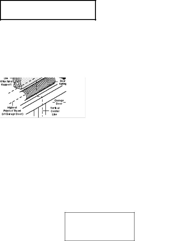
Remember, you can fasten the header bracket within 4 feet of the left or right of the door center only if a torsion spring or center bearing plate is in the way; or you can attach it to the ceiling (refer to page 10) when clearance is minimal. (It may be mounted on the wall upside down if necessary, to gain approximately 1/2".)
If you need to install the header bracket on a 2x4 (on wall or ceiling), use lag screws (not supplied) to securely fasten the 2x4 to structural supports as shown here and on page 9.
• Open your door to the highest point of travel as shown. Draw an intersecting horizontal line on the header wall 3" above the high point. This height will provide travel clearance for the top edge of the door.
Ceiling |
|
Header |
|
Wall |
Track |
3" |
|
Highest Point |
|
of Travel |
|
Door |
|
Header |
|
|
Wall |
Track |
|
3" |
||
|
||
Highest Point |
||
of Travel |
||
Door |
|
|
Sectional door |
One-piece door |
with curved track |
with horizontal track |
Proceed to Step 2, page 10.
8
ONE-PIECE Door Without Track
Read the Safety Instructions on page 8. They also apply to doors without tracks.
•Close the door and mark the inside vertical centerline of your garage door. Extend the line onto the header wall above door.
If headroom clearance is minimal, you can install the header bracket on the ceiling. See page 10.
•If you need to install the header bracket on a 2x4 (on wall or ceiling), use lag screws (not supplied) to securely fasten the 2x4 to structural supports as shown.
Unfinished
Header Wall |
Vertical |
Ceiling |
|
||
|
|
|
|
Centerline |
2x4 |
|
|
Structural Supports
Vertical |
2x4 |
|
Header Support |
||
Centerline of |
||
|
||
Garage Door |
OPTIONAL CEILING MOUNT |
|
|
||
|
FOR HEADER BRACKET |
|
Header Wall |
|
|
Highest Point |
|
|
of Travel |
|
Door |
|
|
Jamb |
Distance |
|
Hardware |
||
|
||
|
Floor |
One-piece door without track jamb hardware
•Open your door to the highest point of travel as shown. Measure the distance from the top of the door to the floor. Subtract the actual height of the door. Add 8" to the remainder. (See Example).
•Close the door and draw an intersecting horizontal line on the header wall at the determined height.
If the total number of inches exceeds the height available in your garage, use the maximum height possible, or refer to page 10 for ceiling installation.
Header |
Highest Point |
Wall |
of Travel |
Door |
Distance |
|
|
Pivot |
|
|
Floor |
One-piece door without track pivot hardware
EXAMPLE |
|
|
Distance from top of door |
|
|
(at highest point of travel) to floor................................ |
92" |
|
Actual height of door................................................... |
|
-88" |
Remainder....................................................................... |
4" |
|
Add .............................................................................. |
+8". |
|
Bracket height on header wall .................................... |
=12" |
|
(Measure UP from top of CLOSED door.) |
|
|
Proceed to Step 2, page 10.
9
Installation Step 2
Install the Header Bracket
Fastening the Header Bracket to the Wall
•Center the bracket on the vertical guideline with the bottom edge of the bracket on the horizontal line as shown (with the arrow pointing toward the ceiling).
•Mark either set of bracket holes (do not use the holes designated for ceiling mount). Drill 3/16" pilot holes and fasten the bracket securely to a structural support with the hardware provided.
You can attach the header bracket either to the wall above the garage door, or to the ceiling. Follow the instructions which will work best for your particular requirements.
Fastening the Header Bracket to the Ceiling
•Extend the vertical guideline onto the ceiling as shown.
•Center the bracket on the vertical mark, no more than 6" from the wall. Make sure the arrow is pointing toward the wall. The bracket can be mounted flush against the ceiling when clearance is minimal.
•Mark holes designated for ceiling mount only. Drill 3/16" pilot holes and fasten bracket securely to a structural support with the hardware provided.
Hardware Shown Actual Size
10
Installation Step 3
Attach the Rail to the Header Bracket
•Position the opener on the garage floor below the header bracket. Use packing material as a protective base.
If the door spring is in the way you’ll need help. Have someone hold the opener securely on a temporary support to allow the rail to clear the spring.
•Position the rail bracket against the header bracket.
•Align the bracket holes and join with a clevis pin as shown.
•Insert a ring fastener to secure.
Hardware Shown Actual Size
11
Loading...