

Central Machinery 67456 Operating, And Servicing Instructions
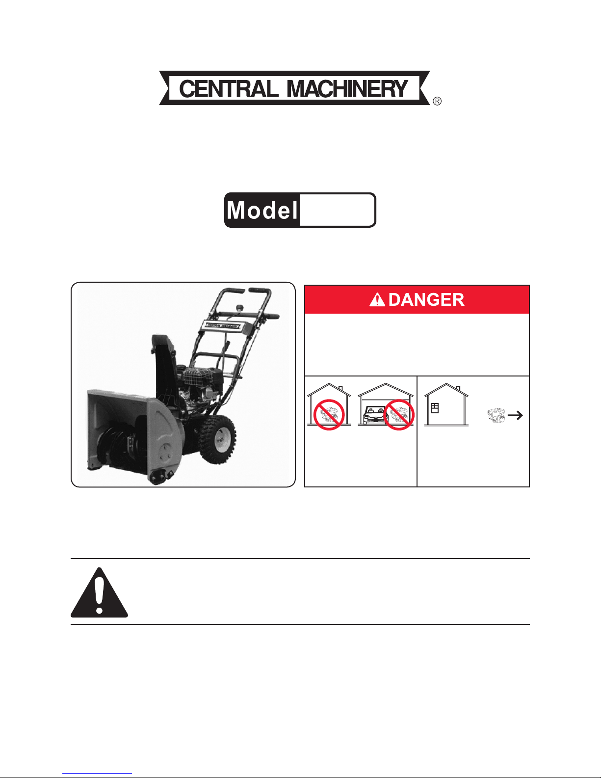
5.5HP 21” TWO-STAGE
SNOW BLOWER
67456
SET UP, OPERATING, AND SERVICING
INSTRUCTIONS
Using an engine indoors CAN KILL YOU IN
MINUTES.
Engine exhaust contains carbon monoxide.
This is a poison you cannot see or smell.
NEVER use inside
a home or garage,
EVEN IF doors and
windows are open.
Distributed exclusively by Harbor Freight Tools®.
3491 Mission Oaks Blvd., Camarillo, CA 93011
Visit our website at: http://www.harborfreight.com
Only use OUTSIDE
and far away from
windows, doors, and
vents.
Read this material before using this product.
Failure to do so can result in serious injury.
SAVE THIS MANUAL.
Copyright© 2009 by Harbor Freight Tools®. All rights reserved. No portion of this manual or any artwork
contained herein may be reproduced in any shape or form without the express written consent of
Harbor Freight Tools. Diagrams within this manual may not be drawn proportionally. Due to continuing
improvements, actual product may differ slightly from the product described herein. Tools required for
assembly and service may not be included.
For technical questions or replacement parts, please call 1-800-444-3353.

CONTENTS
IMPORTANT SAFETY
INFORMATION ............................ 4
VIBRATION HAZARD: ..................7
SERVICE PRECAUTIONS .............8
BASIC SPECIFICATIONS .............9
UNPACKING ..................................9
SET UP INSTRUCTIONS .............10
CLEANING, MAINTENANCE, AND
LUBRICATION SCHEDULE ..........20
AFTER INITIAL 20
OPERATION HOUR PERIOD: . 20
EVERY 25 OPERATION
HOURS THEREAFTER: ...........20
EVERY 50 OPERATION
HOURS: ....................................20
EVERY 100 OPERATION
HOURS: ....................................21
EVERY 300 OPERATION
HOURS: ....................................21
COMPONENTS AND CONTROLS ..10
ASSEMBLY .................................. 11
OPERATING INSTRUCTIONS ....13
ENGINE CONTROLS .......................13
PRE-START CHECKLIST ................13
CHECKING AND FILLING
ENGINE OIL .............................14
CHECKING AND FILLING FUEL 15
STARTING THE ENGINE .................15
START PROCEDURE .................15
BREAK-IN PERIOD ....................16
TO STOP THE ENGINE....................16
OPERATING THE SNOW BLOWER 16
SET UP ........................................16
OPERATION ................................17
SNOW BLOWER PRACTICES ...17
CHUTE CLEAN-OUT ..................17
TECHNICAL SPECIFICATIONS .. 18
STORAGE ........................................21
TROUBLESHOOTING ......................22
MAIN (A) PARTS LIST &
ASSEMBLY DIAGRAM .............24
AUGER (B) PARTS LIST &
ASSEMBLY DIAGRAM .............25
BODY (C) PARTS LIST
DIAGRAM ..................................26
BODY (C) ASSEMBLY
DIAGRAM ..................................27
HANDLE (D) PARTS LIST &
ASSEMBLY DIAGRAM .............28
CYLINDER HEAD PARTS LIST
& ASSEMBLY DIAGRAM ..........29
CRANKCASE PARTS LIST &
ASSEMBLY DIAGRAM .............30
SERVICING ..................................18
MAINTENANCE PROCEDURES .....19
ENGINE OIL CHANGE ...............19
AIR FILTER ELEMENT
MAINTENANCE .......................19
SPARK PLUG MAINTENANCE ..19
FUEL FILTER REPLACEMENT ..20
Page 2 For technical questions, please call 1-800-444-3353. SKU 67456
CRANKCASE COVER PARTS
LIST & ASSEMBLY DIAGRAM . 31
CRANKSHAFT, PISTON &
CAMSHAFT PARTS LIST &
ASSEMBLY DIAGRAM .............32

STARTER PARTS LIST &
ASSEMBLY DIAGRAM .............33
DIVERSION ASSEMBLY &
CARBURETOR PARTS LIST &
ASSEMBLY DIAGRAM .............34
FLYWHEEL & IGNITION PARTS
LIST & ASSEMBLY DIAGRAM . 35
CONTROL SYSTEM & AIR
CLEANER PARTS LIST &
ASSEMBLY DIAGRAM .............36
MUFFLER & FUEL TANK
PARTS LIST & ASSEMBLY
DIAGRAM ..................................37
LIMITED 1 YEAR / 90 DAY
WARRANTY ..............................38
EMISSION CONTROL SYSTEM
WARRANTY ..............................38
Page 3For technical questions, please call 1-800-444-3353.SKU 67456
SAVE THIS MANUAL
Keep this manual for the safety
warnings and precautions, assembly,
operating, inspection, maintenance and
cleaning procedures. Write the product’s
serial number in the back of the manual
near the assembly diagram (or month
and year of purchase if product has no
number). Keep this manual and the
receipt in a safe and dry place for future
reference.
IMPORTANT SAFETY
INFORMATION
In this manual, on the labeling,
and all other information
provided with this product:
This is the safety alert
symbol. It is used to alert
you to potential personal
injury hazards. Obey all
safety messages that
follow this symbol to avoid
possible injury or death.
not avoided, could result in
minor or moderate injury.
NOTICE is used to
address practices
not related to personal injury.
CAUTION, without
the safety alert
symbol, is used to address
practices not related to
personal injury.
WARNING! Read all instructions.
Failure to follow all instructions
listed below may result in re,
serious injury and/or DEATH.
The warnings and precautions
discussed in this manual cannot
cover all possible conditions and
situations that may occur. It must
be understood by the operator that
common sense and caution are
factors which cannot be built into
this product, but must be supplied
by the operator.
SAVE THESE INSTRUCTIONS
SET UP PRECAUTIONS
DANGER indicates
a hazardous
situation which, if not
avoided, will result in death or
serious injury.
WARNING
indicates a
hazardous situation which, if
not avoided, could result in
death or serious injury.
CAUTION, used
with the safety
alert symbol, indicates a
hazardous situation which, if
Page 4 For technical questions, please call 1-800-444-3353. SKU 67456
Gasoline fuel and fumes are 1.
ammable, and potentially explosive.
Use proper fuel storage and handling
procedures. Do not store fuel or
other ammable materials nearby.
Have multiple ABC class re 2.
extinguishers nearby.
Operation of this equipment may 3.
create sparks that can start res
around dry vegetation.
A spark arrestor may be required.
The operator should contact
local re agencies for laws or
regulations relating to re prevention
requirements.
pulleys before operation. Do not
operate without all guards in place.
Set up and use only on a at, level, 4.
well-ventilated surface.
Wear ANSI-approved safety goggles, 5.
heavy-duty work gloves, and dust
mask/respirator during set up.
Use only oil and fuel recommended 6.
in the “Specications” section of this
manual.
OPERATING PRECAUTIONS
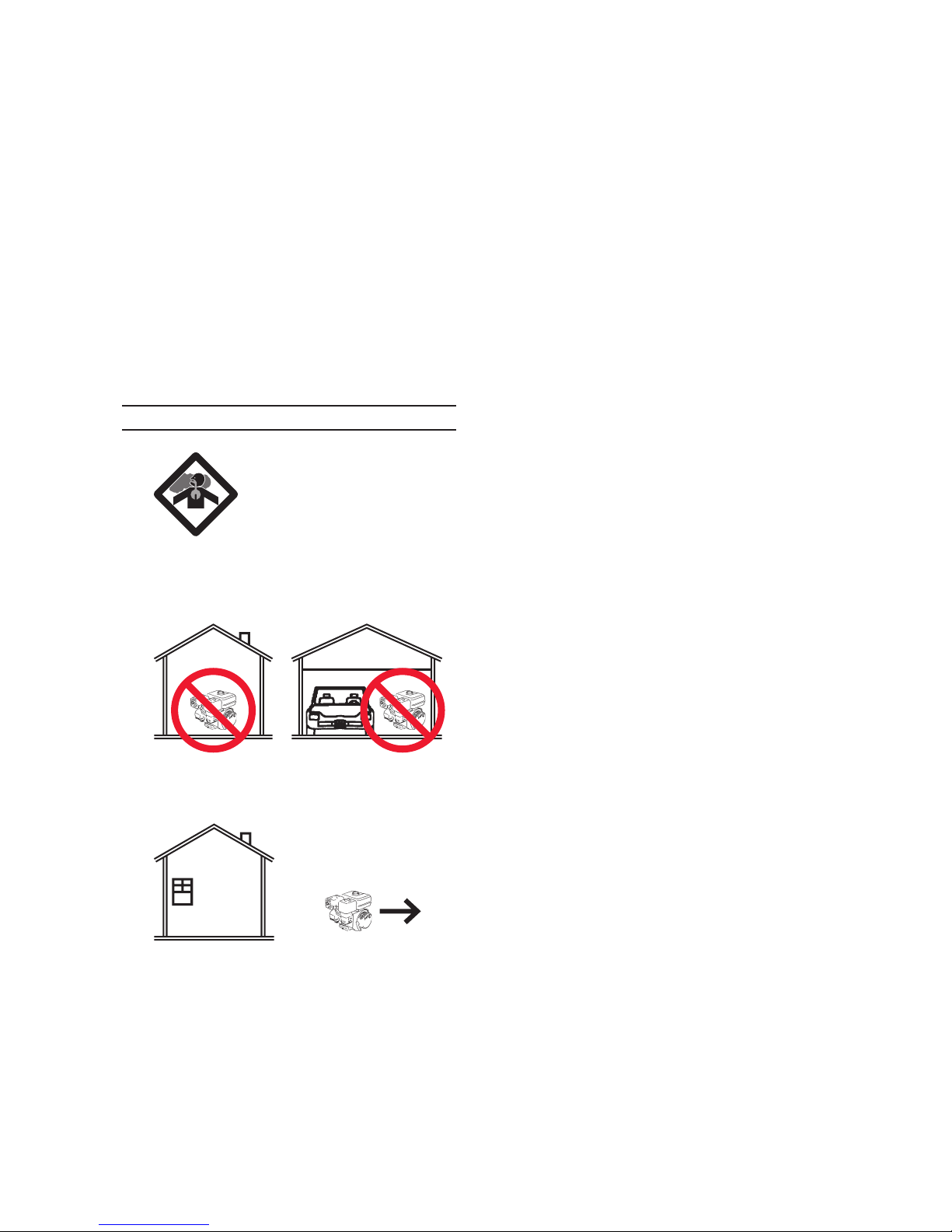
1. CARBON MONOXIDE
HAZARD
Using an engine indoors
CAN KILL YOU IN
MINUTES.
Engine exhaust contains carbon
monoxide. This is a poison you
cannot see or smell.
Disengage Drive Control Lever and 4.
Auger Control Lever before starting
engine.
Do not tie down any Control Lever.5.
Do not use near other people, 6.
near steep slopes, or where rocks,
branches, or other debris may be
present.
Keep children away. Do not allow 7.
children to operate Blower.
Point discharge in safe direction. 8.
Rocks, ice and other objects will be
forcefully thrown from discharge.
Stop engine and disconnect spark 9.
plug after use and before service or
unclogging.
To prevent serious injury and 10.
entanglement, shut off engine
and disconnect spark plug before
unclogging. Use only plastic tool for
unclogging.
NEVER use inside a home or garage,
EVEN IF doors and windows are
open.
Only use OUTSIDE and far away
from windows, doors, and vents.
Keep clear of augers while engine 2.
is running.
To prevent serious injury and 3.
entanglement, guard must cover
Wear ANSI-approved safety goggles 11.
during operation, unclogging, and
service.
Read manual before setup and/or 12.
use.
Release Drive Control Lever before 13.
changing gears.
Do not leave the equipment 14.
unattended when it is running. Turn
off the engine (and remove safety
keys, if available) before leaving the
work area.
Fire Hazard! Do not ll gas tank while 15.
engine is running. Do not operate
Page 5For technical questions, please call 1-800-444-3353.SKU 67456

if gasoline has been spilled. Clean
spilled gasoline before starting
engine. Do not operate near a pilot
light, open ame, or ammable
material, liquids or gases.
Do not touch engine during use. Let 16.
engine cool down after use.
Never store fuel or other ammable 17.
materials near the engine.
Only use a suitable means of 18.
transport and lifting devices with
sufcient weight bearing capacity
when transporting the Snow Blower.
Secure the Snow Blower on transport 19.
vehicles to prevent the tool from
rolling, slipping, and tilting.
presence of ammable liquids, gases,
or dust. Gasoline-powered engines
may ignite the dust or fumes.
Stay alert, watch what you are 25.
doing and use common sense when
operating this piece of equipment.
Do not use this piece of equipment
while tired or under the inuence of
drugs, alcohol or medication.
Do not overreach. Keep proper 26.
footing and balance at all times.
This enables better control of the
equipment in unexpected situations.
Use this equipment with both hands 27.
only. Using equipment with only
one hand can easily result in loss of
control.
Do not allow anyone in front of Snow 20.
Blower, or direct the discharge at
windows or bystanders.
Before use, carefully inspect the area 21.
where the Snow Blower is to be used,
and remove all foreign objects.
People with pacemakers should 22.
consult their physician(s) before
use. Electromagnetic elds in close
proximity to a heart pacemaker
could cause pacemaker interference
or pacemaker failure. Caution is
necessary when near the engine’s
magneto or recoil starter.
Use only accessories that are 23.
recommended by Harbor Freight
Tools for your model. Accessories
that may be suitable for one piece of
equipment may become hazardous
when used on another piece of
equipment.
Do not operate in explosive 24.
atmospheres, such as in the
Dress properly. Do not wear loose 28.
clothing or jewelry. Keep hair,
clothing and gloves away from
moving parts. Loose clothes, jewelry
or long hair can be caught in moving
parts.
Parts, especially exhaust system 29.
components, get very hot during use.
Stay clear of hot parts.
Do not cover the engine or equipment 30.
during operation.
Keep the equipment, engine, and 31.
surrounding area clean at all times.
Use the equipment, accessories, etc., 32.
in accordance with these instructions
and in the manner intended for the
particular type of equipment, taking
into account the working conditions
and the work to be performed. Use
of the equipment for operations
different from those intended could
result in a hazardous situation.
Page 6 For technical questions, please call 1-800-444-3353. SKU 67456

Do not operate the equipment with 33.
known leaks in the engine’s fuel
system.
This product contains or, when 34.
used, produces a chemical known
to the State of California to cause
cancer and birth defects or other
reproductive harm. (California Health
& Safety Code § 25249.5, et seq.)
When spills of fuel or oil occur, they 35.
must be cleaned up immediately.
Dispose of uids and cleaning
materials as per any local, state,
or federal codes and regulations.
Store oil rags in a bottom-ventilated,
covered, metal container.
Keep hands and feet away from 36.
moving parts. Do not reach over or
across equipment while operating.
Anyone using vibrating tools regularly 1.
or for an extended period should
rst be examined by a doctor and
then have regular medical checkups to ensure medical problems are
not being caused or worsened from
use. Pregnant women or people
who have impaired blood circulation
to the hand, past hand injuries,
nervous system disorders, diabetes,
or Raynaud’s Disease should not use
this tool. If you feel any symptoms
related to vibration (such as tingling,
numbness, and white or blue ngers),
seek medical advice as soon as
possible.
Do not smoke during use. Nicotine 2.
reduces the blood supply to the
hands and ngers, increasing the risk
of vibration-related injury.
Before use, check for misalignment 37.
or binding of moving parts, breakage
of parts, and any other condition
that may affect the equipment’s
operation. If damaged, have the
equipment serviced before using.
Many accidents are caused by poorly
maintained equipment.
Use the correct equipment for the 38.
application. Do not modify the
equipment and do not use the
equipment for a purpose for which it
is not intended.
Vibration Hazard:
This tool vibrates during use.
Repeated or long-term exposure to
vibration may cause temporary or
permanent physical injury, particularly
to the hands, arms and shoulders. To
reduce the risk of vibration-related
injury:
Wear suitable gloves to reduce the 3.
vibration effects on the user.
Use tools with the lowest vibration 4.
when there is a choice between
different processes.
Include vibration-free periods each 5.
day of work.
Grip tool as lightly as possible (while 6.
still keeping safe control of it). Let
the tool do the work.
To reduce vibration, maintain the tool 7.
as explained in this manual. If any
abnormal vibration occurs, stop use
immediately.
Page 7For technical questions, please call 1-800-444-3353.SKU 67456

SERVICE PRECAUTIONS
Before service, maintenance, or 1.
cleaning:
Turn the engine switch to its a.
“OFF” position.
Store equipment out of the reach of 7.
children.
Follow scheduled engine and 8.
equipment maintenance.
Refueling Precautions:9.
Allow the engine to completely b.
cool.
Then, remove the spark plug c.
wire(s) from the spark plug(s).
Keep all safety guards in place and 2.
in proper working order. Safety
guards include mufer, air cleaner,
mechanical guards, and heat shields,
among other guards.
Do not alter or adjust any part of 3.
the equipment or its engine that
is sealed by the manufacturer
or distributor. Only a qualied
service technician may adjust
parts that may increase or
decrease governed engine speed.
Wear ANSI-approved safety goggles, 4.
heavy-duty work gloves, and dust
mask/respirator during service.
Do not smoke, or allow sparks, a.
ames, or other sources of ignition
around the equipment, especially
when refuelling.
Do not rell the fuel tank while the b.
engine is running or hot.
Do not ll fuel tank to the top. Leave c.
a little room for the fuel to expand as
needed.
Refuel in a well-ventilated area only.d.
After refueling, allow fumes to e.
evaporate prior to starting the
engine.
SAVE THESE
INSTRUCTIONS.
Maintain labels and nameplates 5.
on the equipment. These carry
important information. If unreadable
or missing, contact Harbor Freight
Tools for a replacement.
Have the equipment serviced by a 6.
qualied repair person using only
identical replacement parts. This
will ensure that the safety of the
equipment is maintained. Do not
attempt any service or maintenance
procedures not explained in this
manual or any procedures that you
are uncertain about your ability to
perform safely or correctly.
Page 8 For technical questions, please call 1-800-444-3353. SKU 67456

BASIC SPECIFICATIONS
UNPACKING
Engine Rating
Type
Fuel
Capacity 1 Gallon
Type
Engine Oil
Capacity 0.63 Quarts
Sound Level 87 dB
Tire
Drive Gears
Snow Throwing
Distance
Accessories
5.5 Horsepower, Recoil
Start, EPA certied
89+ octane unleaded
gasoline
SAE 10W-30
(above 32° F)
SAE 5W-30
(at 32° F or below)
13” x 4.10 - 6 NHS, 4 PR
24 PSI
Five Forward:
0.9, 1.2, 1.5, 1.8, 2.5 mph
Two Reverse:
0.9, 1.2 mph
Up to 50 Ft.
Spark Plug Wrench, (3)
Double Sided Wrenches,
Accessory Pouch, Plastic
Snow Removal Tool
When unpacking, make sure that the
item is intact and undamaged. If any parts
are missing or broken, please call Harbor
Freight Tools at 1-800-444-3353 as soon
as possible.
Note: Additional specications found
in the TECHNICAL ENGINE
SPECIFICATIONS chart in this
manual.
The emission control system for
this Generator’s Engine is warranted for
standards set by the U.S. Environmental
Protection Agency. For warranty
information, refer to the last pages of this
manual.
At high altitudes, the engine’s
carburetor, governor (if so equipped), and
any other parts that control the fuel-air
ratio will need to be adjusted by a qualied
mechanic to allow efcient high-altitude
use and to prevent damage to the engine
and any other devices used with this
product.
Page 9For technical questions, please call 1-800-444-3353.SKU 67456
SET UP INSTRUCTIONS
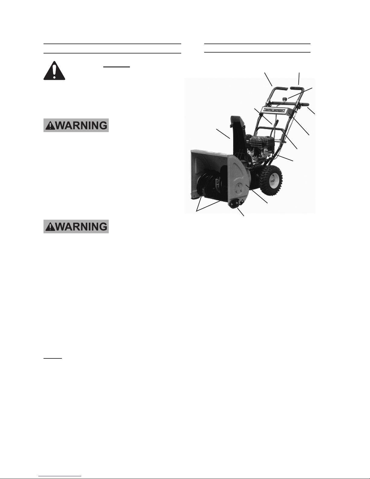
Components and Controls
Read the ENTIRE IMPORTANT
SAFETY INFORMATION
section at the beginning of this
manual including all text under
subheadings therein before set
up or use of this product.
TO PREVENT
SERIOUS INJURY
FROM ACCIDENTAL
STARTING:
Turn the Power Switch of the
equipment to its “OFF”
position, wait for the engine to
cool, and disconnect the
spark plug wire(s) before
assembling or making any
adjustments to the equipment.
TO PREVENT
SERIOUS INJURY:
Operate only with proper
spark arrestor installed.
Chute
Assembly
(30A)
Augers
(13B/26B)
Figure 1
Drive
Control
Gear
Shift
Handle
(44A)
Hopper Assembly (1A)
Skid Plate (4B)
Auger
Control
Push Frame (43C)
Engine (35C)
Chute
Control
Lever &
Knob
(12A/9A)
Upper
Handle
(1D)
Panel (2D)
Operation of this equipment
may create sparks that
can start res around dry
vegetation.
A spark arrestor may be
required.
The operator should contact
local re agencies for laws
or regulations relating to re
prevention requirements.
Note: For additional information regarding
the parts listed in the following pages,
refer to the Assembly Diagram near
the end of this manual.
Page 10 For technical questions, please call 1-800-444-3353. SKU 67456

ASSEMBLY
Identify all the parts before assembly.1.
Upper
Handle
(1D)
Bolts (4A)
Figure 2
Push Frame (43C)
Wing
Knobs
(39A)
Shaped
Washer
(45A)
2. To attach the Upper Handle (1D) to
the Push Frame (43C):
Hold the Upper Handle (1D) on the a.
outside of the Push Frame (43C)
aligning the two holes on each side.
Slide the Bolts (4A) through the b.
holes from the outside of the Upper
Handle.
Thread the Wing Knobs (39A) on the c.
upper Bolts.
Panel (2D)
Lock
Bolts (17D)
Nuts
(19D)
Figure 3
3. To attach the Panel (2D) to the Upper
Handle:
Remove the Bolts (17D), and Lock a.
Nuts (19D) from the Upper Handle
sides.
Align the Panel over the holes in the b.
side of the Upper Handle.
Replace the Bolts and Lock Nuts, c.
being careful to replace the spring
on the upper Bolts.
Gear
Shift
Handle
(44A)
Lock
Nut
(5A)
Slide the Shaped Washers (45A) d.
and thread the Wing Knobs on the
lower Bolts.
Bolt
(38A)
Gear Connector (48C)
Figure 4
4. To attach the Gear Shift Handle (44A)
to the Gear Connector (48C):
Align the Gear Shift Handle and a.
Gear Connector holes.
Attach with Bolts (38A) and Lock b.
Nuts (5A).
Page 11For technical questions, please call 1-800-444-3353.SKU 67456
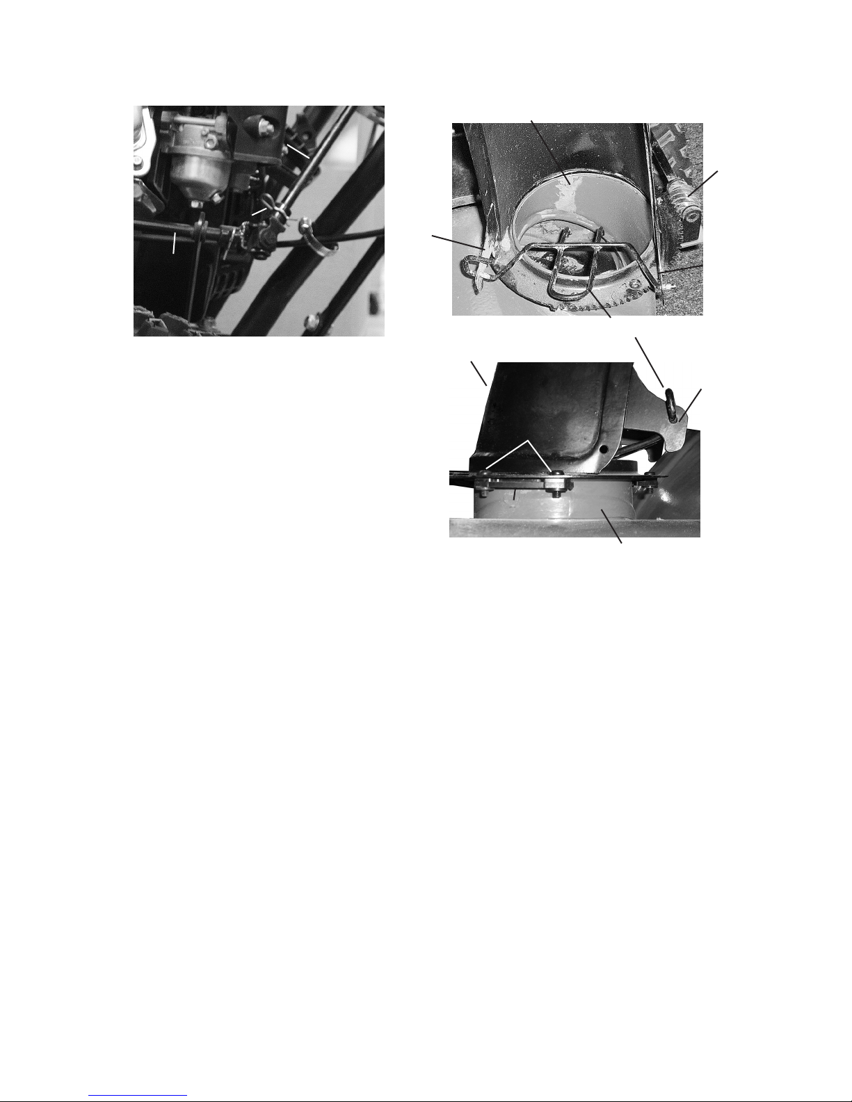
Chute
Control
Lever
(12A)
Chute Assembly (30A)
Gear (24A)
R-Pin (17A)
Connecting
Rod (20A)
Figure 5
5. To attach the Chute Control Lever
(12A) to the Connecting Rod (20A):
Insert the Chute Control Lever into a.
the slot at the end of the Connecting
Rod.
Align the holes in both parts and b.
insert the R-Pin (17A).
Flange
Guard Rail (31A)
Chute Assembly (30A)
Bolt (32A)
Brace (33A)
Figure 6
Hopper Assembly (1A)
6. To attach the Chute Assembly (30A)
to the Hopper Assembly (1A):
Flange
Flange
Thread the looped end of the Guard a.
Rail (31A) through the hole in the
left ange of the Chute Assembly
(30A). Insert the other end through
the other ange hole as shown in the
upper photo.
Align the holes in the rim of the b.
Chute Assembly with the holes in
the rim of the Hopper Assembly (1A)
opening. Make sure the toothed
section of the rim lines up with the
Gear (24A) so that when the Chute
Assembly is rotated it can face all
the way from the left to the right side
of the Snow Blower.
Attach the Chute to the Hopper c.
Assembly, using three Braces (33A)
with Screws (32A) (See Figure 6).
Page 12 For technical questions, please call 1-800-444-3353. SKU 67456
 Loading...