

Central Machinery 63469 Owner's Manual & Safety Instructions

!"#"$%&'(%)*+#"$*%,$-%.$$/-00)))1.,(+&(2(*"3.$14&5
65,"7%&'(%$*4.8"4,7%#'//&($%,$-%/(&9'4$#'//&($:.,(+&(2(*"3.$14&5
Owner’s Manual & Safety Instructions
Save This Manual%Keep this manual for the safety warnings and precautions, assembly,
operating, inspection, maintenance and cleaning procedures. Write the product’s serial number in the
back of the manual near the assembly diagram (or month and year of purchase if product has no number).
Keep this manual and the receipt in a safe and dry place for future reference. 18a
When unpacking, make sure that the product is intact
and undamaged. If any parts are missing or broken,
please call 1-888-866-5797 as soon as possible.
Copyright© 2016 by Harbor Freight Tools®. All rights reserved.
No portion of this manual or any artwork contained herein may be reproduced in
any shape or form without the express written consent of Harbor Freight Tools.
Diagrams within this manual may not be drawn proportionally. Due to continuing
improvements, actual product may differ slightly from the product described herein.
To ol s re q u ir e d f o r a s s e mb l y a n d s e r vi c e m a y n o t b e in c l ud e d .
;*,9%$."#%5,$*(",7%+*2&(*%'#"83%$."#%/(&9'4$1%
<,"7'(*%$&%9&%#&%4,8%(*#'7$%"8%#*("&'#%"8='(>1%
?@!6%ABC?%D@EF@G1

Page 2 <&(%$*4.8"4,7%H'*#$"&8#I%/7*,#*%4,77%JKLLLKLMMKNOPO1 Item 63469
?@<6AQ RS6;@ACRE D@CEA6E@ET6?6AFS
A,+7*%&2%T&8$*8$#
Safety ......................................................... 3
Specifications ............................................. 6
Setup .......................................................... 7
Operation .................................................... 9
Maintenance .............................................. 18
Parts List and Diagram .............................. 22
Warranty .................................................... 32
U@;ECEV%?QDWRG?%@EX%X6<CECACRE?
This is the safety alert symbol. It is used to alert you to potential
personal injury hazards. Obey all safety messages that
follow this symbol to avoid possible injury or death.
Indicates a hazardous situation which, if not avoided,
will result in death or serious injury.
Indicates a hazardous situation which, if not avoided,
could result in death or serious injury.
Indicates a hazardous situation which, if not avoided,
could result in minor or moderate injury.
Addresses practices not related to personal injury.

Page 3<&(%$*4.8"4,7%H'*#$"&8#I%/7*,#*%4,77%JKLLLKLMMKNOPO1Item 63469
?@<6AQRS6;@ACRED@CEA6E@ET6 ?6AFS
CDSR;A@EA%?@<6AQ%CE<R;D@ACRE
V*8*(,7%A&&7%?,2*$>%U,(8"83#
;*,9%,77%#,2*$>%),(8"83#%,89%"8#$('4$"&8#1%%
Failure to follow the warnings and instructions may result in electric shock, fire and/or serious injury.
?,Y*%,77%),(8"83#%,89%"8#$('4$"&8#%2&(%2'$'(*%(*2*(*84*1
1. KEEP GUARDS IN PLACE and in working order.
2. REMOVE ADJUSTING KEYS AND
WRENCHES. Form habit of checking to
see that keys and adjusting wrenches are
removed from tool before turning it on.
3. KEEP WORK AREA CLEAN.
Cluttered areas and benches invite accidents.
4. DON’T USE IN DANGEROUS ENVIRONMENT.
Don’t use power tools in damp or wet locations,
or expose them to rain. Keep work area well lighted.
5. KEEP CHILDREN AWAY. All visitors should
be kept safe distance from work area.
6. MAKE WORKSHOP KID PROOF with padlocks,
master switches, or by removing starter keys.
7. DON’T FORCE TOOL. It will do the job better
and safer at the rate for which it was designed.
8. USE RIGHT TOOL. Don’t force tool or attachment
to do a job for which it was not designed.
A,+7*%@-%%;6TRDD6EX6X%DCECDFD%UC;6%V@FV6%
<R;%6ZA6E?CRE%TR;X?%
[J\]%\^]%!RGA_
E@D6SG@A6%
@DS6;6?
[,$%2'77%7&,9_
6ZA6E?CRE%TR;X%
G6EVAB
25′ 50′ 100′ 150′
0 – 6 18 16 16 14
6.1 – 10 18 16 14 12
10.1 – 12 16 16 14 12
12.1 – 16 14 12 X&%8&$%'#*1
9. USE PROPER EXTENSION CORD. Make sure your
extension cord is in good condition. When using
an extension cord, be sure to use one heavy
enough to carry the current your product will draw.
An undersized cord will cause a drop in line voltage
resulting in loss of power and overheating. %
Table A shows the correct size to use depending
on cord length and nameplate ampere rating.
If in doubt, use the next heavier gauge.
The smaller the gauge number, the heavier the cord.
10. WEAR PROPER APPAREL. Do not wear
loose clothing, gloves, neckties, rings, bracelets,
or other jewelry which may get caught in moving
parts. Nonslip footwear is recommended.
Wear protective hair covering to contain long hair.
11. ALWAYS USE SAFETY GLASSES. Also use
face or dust mask if cutting operation is dusty.
Everyday eyeglasses only have impact resistant
lenses, they are NOT safety glasses.
12. SECURE WORK. Use clamps or a vise to
hold work when practical. It’s safer than using your
hand and it frees both hands to operate tool.
13. DON’T OVERREACH.
Keep proper footing and balance at all times.
14. MAINTAIN TOOLS WITH CARE. Keep
tools sharp and clean for best and safest
performance. Follow instructions for
lubricating and changing accessories.
15. DISCONNECT TOOLS before servicing;
when changing accessories, such as
blades, bits, cutters, and the like.
16. REDUCE THE RISK OF UNINTENTIONAL
STARTING. Make sure switch is in
off position before plugging in.
17. USE RECOMMENDED ACCESSORIES.
Consult the owner’s manual for recommended
accessories. The use of improper accessories
may cause risk of injury to persons.
18. NEVER STAND ON TOOL.
Serious injury could occur if the tool is tipped or
if the cutting tool is unintentionally contacted.
19. CHECK DAMAGED PARTS. Before further use
of the tool, a guard or other part that is damaged
should be carefully checked to determine that
it will operate properly and perform its intended
function – check for alignment of moving parts,
binding of moving parts, breakage of parts,
mounting, and any other conditions that may
affect its operation. A guard or other part that is
damaged should be properly repaired or replaced.
20. NEVER LEAVE TOOL RUNNING UNATTENDED.
TURN POWER OFF. Don’t leave tool
until it comes to a complete stop.
Page 4 <&(%$*4.8"4,7%H'*#$"&8#I%/7*,#*%4,77%JKLLLKLMMKNOPO1 Item 63469
?@<6AQ RS6;@ACRE D@CEA6E@ET6?6AFS
V(&'89"83%C8#$('4$"&8#
%
AR%S;6!6EA%6G6TA;CT%?BRT`%@EX%X6@AB%<;RD%CETR;;6TA%
V;RFEXCEV%UC;6%TREE6TACRE%;6@X%@EX%<RGGRU%AB6?6%CE?A;FTACRE?-
JJ]KJ\]%!@T%V(&'89*9%A&&7#-%A&&7#%)"$.%A.(**%S(&83%S7'3#
1. In the event of a malfunction or breakdown,
grounding provides a path of least resistance for
electric current to reduce the risk of electric shock.
This tool is equipped with an electric cord having an
equipment-grounding conductor and a grounding
plug. The plug must be plugged into a matching
outlet that is properly installed and grounded in
accordance with all local codes and ordinances.
2. Do not modify the plug provided – if it will
not fit the outlet, have the proper outlet
installed by a qualified electrician.
3. Improper connection of the equipment-grounding
conductor can result in a risk of electric shock.
The conductor with insulation having an outer
surface that is green with or without yellow
stripes is the equipment-grounding conductor.
If repair or replacement of the electric cord or
plug is necessary, do not connect the equipmentgrounding conductor to a live terminal.
4. Check with a qualified electrician or service
personnel if the grounding instructions are
not completely understood, or if in doubt as
to whether the tool is properly grounded.
5. Use only 3-wire extension cords that
have 3-prong grounding plugs and 3-pole
receptacles that accept the tool’s plug.
6. Repair or replace damaged or
worn cord immediately.
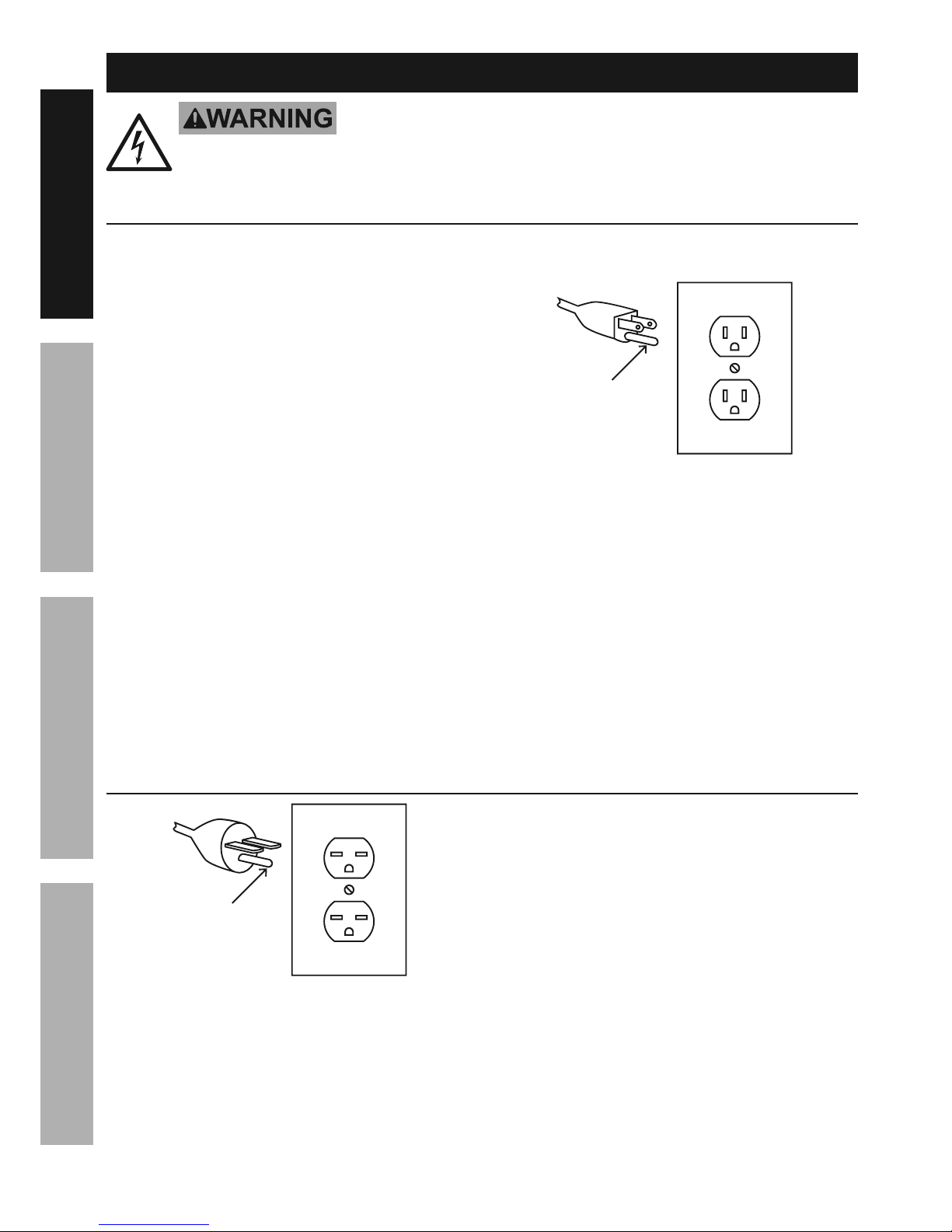
V(&'89"83%
S"8
J\N%!@T%aKS(&83%S7'3%,89%R'$7*$
[2&(%'/%$&%J\N%!@T%,89%'/%$&%JN%@_
7. This tool is intended for use on a circuit that has
an outlet that looks like the one illustrated above in
J\N%!@T%aKS(&83%S7'3%,89%R'$7*$. The tool has
a grounding plug that looks like the plug illustrated
above in J\N%!@T%aKS(&83%S7'3%,89%R'$7*$.
8. The outlet must be properly installed and grounded
in accordance with all codes and ordinances.
9. Do not use an adapter to connect
this tool to a different outlet.
\\]K\^]%!@T%A&&7#
\N]%!@T%aKS(&83%S7'3%,89%R'$7*$
[2&(%'/%$&%\N]%!@T%,89%'/%$&%JN%@_
V(&'89"83%
S"8
1. This tool is intended for use on a circuit that has
an outlet that looks like the one illustrated above in
\N]%!@T%aKS(&83%S7'3%,89%R'$7*$.
The tool has a grounding plug
that looks like the plug illustrated above in
\N]%!@T%aKS(&83%S7'3%,89%R'$7*$.
Make sure the tool is connected to an outlet
having the same configuration as the plug.
No adapter is available or should be used with
this tool. If the tool must be reconnected for
use on a different type of electric circuit, the
reconnection should be made by qualified service
personnel; and after reconnection, the tool should
comply with all local codes and ordinances.
2. The 250 VAC plug does not come pre-installed and
will need to be installed by a certified electrician.
3. The plug above is for use on a 15 A circuit.
A different 250 VAC plug and outlet combination
may be used, provided it is rated to handle
the electrical requirements of the tool and
is installed by a certified electrician.

Page 5<&(%$*4.8"4,7%H'*#$"&8#I%/7*,#*%4,77%JKLLLKLMMKNOPO1Item 63469
?@<6AQRS6;@ACRED@CEA6E@ET6 ?6AFS
W,89%?,)%?,2*$>%U,(8"83#
<&(%Q&'(%R)8%?,2*$>%;*,9%C8#$('4$"&8%
D,8',7%W*2&(*%R/*(,$"83%?,)
1. Wear eye protection.
2. Do not remove jammed cutoff pieces
until blade has stopped.
3. Maintain proper adjustment of blade tension,
blade guides, and thrust bearings.
4. Adjust upper guide to just clear workpiece.
5. Hold workpiece firmly against table.
6. Properly adjust the upper blade guide, blade
tension and blade guide bearings before each
use to reduce the risk of injury. See Operating
Instructions for explanation of needed adjustments.
7. Use special care when unpacking or
replacing bandsaw blade. Blade can be
under tension and may suddenly uncoil.
Wear ANSI-approved safety glasses under a
full face shield and heavy-duty work gloves.
8. Place the Band Saw on a flat, level, sturdy
surface capable of supporting the weight of the
Saw and workpieces. “Chock” the Wheels to
prevent the Band Saw from accidentally moving.
9. Before using the Band Saw, confirm the Saw Blade
is properly mounted and is not cracked or bent.
10. Do not cut more than one workpiece at a time.
11. When cutting a large workpiece, support
its entire length properly. If necessary,
use a roller stand (not included).
12. Do not lean on the Band Saw when
the tool is in its upright position.
13. When moving the Band Saw, pivot its
head to the horizontal position.
14. Bring the Saw Blade to full rotational speed
before feeding a workpiece into the Blade.
When turning off the Band Saw, allow the
Saw Blade to spin down and stop on its own.
Do not press against the Saw Blade to stop it.
15. Wear heavy-duty work gloves when
changing the Saw Blade.
16. Turn off the Band Saw and allow the Saw
Blade to completely stop if the Saw Blade is
to be backed out of an uncompleted cut.
17. Use indoors only.
18. If the teeth of the Saw Blade are so far apart that
they straddle the workpiece, severe damage to
the workpiece and/or Saw Blade will result.
19. XR%ERA%RS6;@A6%UCAB%@EQ%VF@;X%
XC?@WG6XI%X@D@V6XI%R;%;6DR!6X1%%D&Y"83%
3',(9#%5'#$%5&Y*%2(**7>%,89%47&#*%"8#$,8$7>1
20. The use of accessories or attachments not
recommended by the manufacturer may
result in a risk of injury to persons.
21. When servicing use only identical replacement parts.
22. Only use safety equipment that has been approved
by an appropriate standards agency. Unapproved
safety equipment may not provide adequate
protection. Eye protection must be ANSI-approved
and breathing protection must be NIOSH-approved
for the specific hazards in the work area.
23. Stay alert, watch what you are doing and use
common sense when operating a power tool.
Do not use a power tool while you are tired or
under the influence of drugs, alcohol or medication.
A moment of inattention while operating power
tools may result in serious personal injury.
24. Industrial applications must follow OSHA guidelines.
25. Maintain labels and nameplates on the tool.
These carry important safety information.
If unreadable or missing, contact
Harbor Freight Tools for a replacement.
26. Avoid unintentional starting.
Prepare to begin work before turning on the tool.
27. People with pacemakers should consult their
physician(s) before use. Electromagnetic fields in
close proximity to heart pacemaker could cause
pacemaker interference or pacemaker failure.
28. The warnings, precautions, and instructions
discussed in this instruction manual cannot cover all
possible conditions and situations that may occur.
It must be understood by the operator that
common sense and caution are factors
which cannot be built into this product,
but must be supplied by the operator.

Page 6 <&(%$*4.8"4,7%H'*#$"&8#I%/7*,#*%4,77%JKLLLKLMMKNOPO1 Item 63469
?@<6AQ RS6;@ACRE D@CEA6E@ET6?6AFS
!"+(,$"&8%?,2*$>
This tool vibrates during use. Repeated or
long-term exposure to vibration may cause
temporary or permanent physical injury,
particularly to the hands, arms and shoulders.
To reduce the risk of vibration-related injury:
1. Anyone using vibrating tools regularly or for an
extended period should first be examined by a
doctor and then have regular medical check-ups
to ensure medical problems are not being caused
or worsened from use. Pregnant women or
people who have impaired blood circulation to
the hand, past hand injuries, nervous system
disorders, diabetes, or Raynaud’s Disease should
not use this tool. If you feel any medical or
physical symptoms related to vibration (such as
tingling, numbness, and white or blue fingers),
seek medical advice as soon as possible.
2. Do not smoke during use. Nicotine reduces
the blood supply to the hands and fingers,
increasing the risk of vibration-related injury.
3. Use tools with the lowest vibration when there
is a choice between different processes.
4. Include vibration-free periods each day of work.
5. Grip workpiece as lightly as possible (while still
keeping safe control of it). Let the tool do the work.
6. To reduce vibration, maintain the tool as
explained in this manual. If any abnormal
vibration occurs, stop use immediately.
%?@!6%AB6?6%CE?A;FTACRE?1
?/*4"2"4,$"&8#
Electrical Rating
120VAC / 60 Hz / 16 A
As wired from the manufacturer.
See pages - 31 for additional wiring options
that only a licensed electrician should attempt.
Motor No Load Speed 1720 RPM
Blade Speeds 90 / 135 / 195 / 255 FPM
Cutting Capacity
7″ Round Stock
7″ x 12″ Rectangular Stock
V-Belt Type 3V-270
Blade Size 93″ L x .75″ W x 0.031″ Thick / 6 TPI
Page 7<&(%$*4.8"4,7%H'*#$"&8#I%/7*,#*%4,77%JKLLLKLMMKNOPO1Item 63469
?@<6AQRS6;@ACRED@CEA6E@ET6 ?6AFS
?*$'/%K%W*2&(*%F#*-
% ;*,9%$.*%6EAC;6%CDSR;A@EA%?@<6AQ%CE<R;D@ACRE%#*4$"&8%,$%$.*%+*3"88"83%&2%$."#%
5,8',7%"847'9"83%,77%$*b$%'89*(%#'+.*,9"83#%$.*(*"8%+*2&(*%#*$%'/%&(%'#*%&2%$."#%/(&9'4$1
AR%S;6!6EA%?6;CRF?%CEcF;Q%<;RD%@TTCX6EA@G%RS6;@ACRE-%
A'(8%$.*%S&)*(%?)"$4.%&2%$.*%$&&7%&22%,89%'8/7'3%$.*%$&&7%2(&5%"$#%*7*4$("4,7%&'$7*$%
+*2&(*%/*(2&(5"83%,8>%/(&4*9'(*%"8%$."#%#*4$"&81
E&$*- For additional information regarding the parts listed in the following pages,
refer to the Assembly Diagram near the end of this manual.
@##*5+7>0D&'8$"83
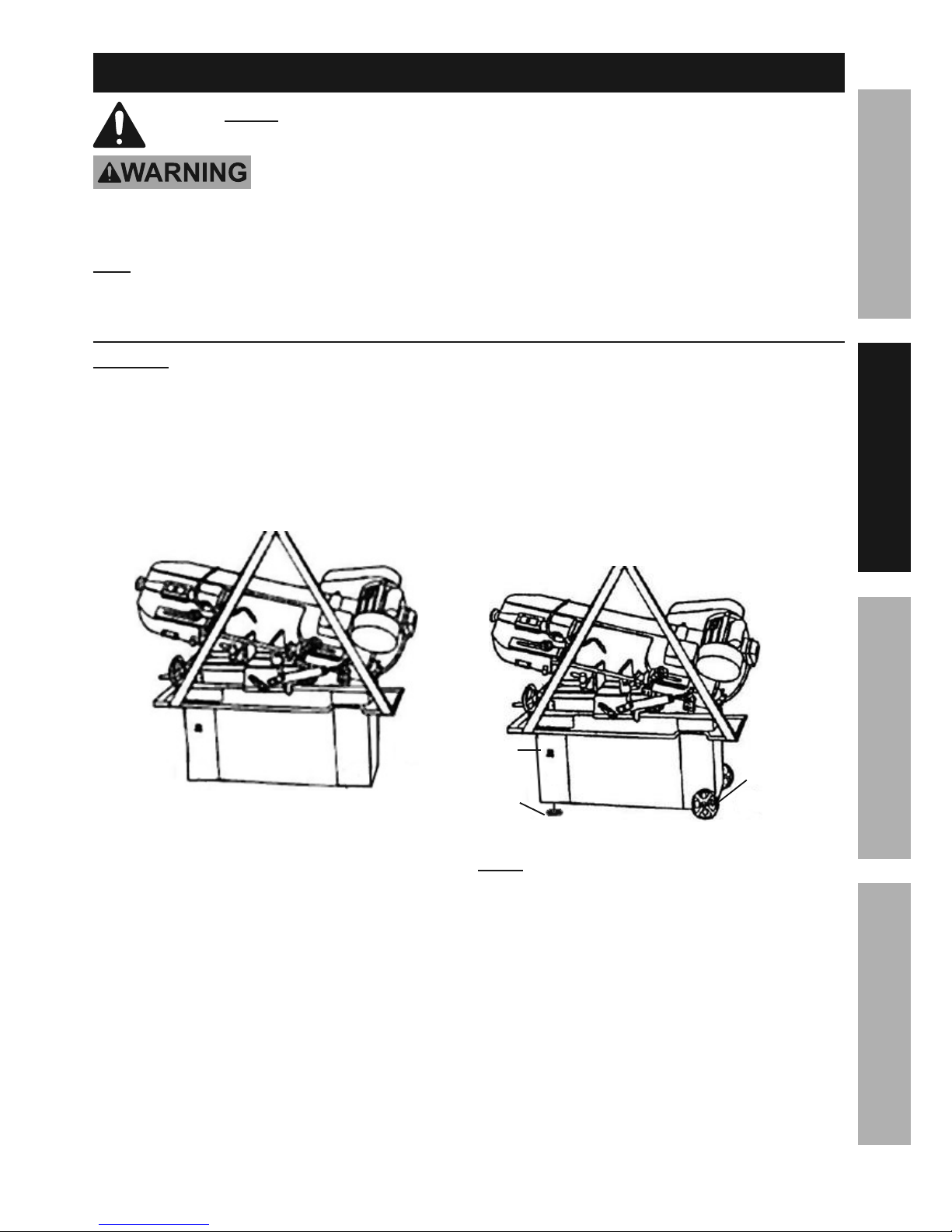
U@;ECEVd To assemble and locate the Bandsaw will
require additional assistance and a proper lifting device.
1. After the Bandsaw and its accessories
are unpacked, make sure its Head is
lowered to its horizontal position.
2. With a proper lifting device, raise the
Bandsaw approximately six inches off
the floor surface. (See Figure A.)
<"3'(*%@
3. Once the Bandsaw is lifted, insert the
Wheel Rod (92-4) through the two holes located
at the bottom/right side of the Stand (77S).
Slide one Wheel (92-2) on each end of the
Wheel Rod. Place one Washer (92-1) on each
end of the Wheel Rod. Insert one Cotter Pin
(92-3) through the hole in each end of the
Wheel Rod. Make sure to bend the Cotter Pins
to secure the Wheels in place. (See Figure B.)
4. Screw in the two Levelers (93) into the two
threaded mounting holes located underneath
the bottom/left side of the Stand.
5. Carefully lower the Bandsaw to the floor
surface. Then turn the two Levelers clockwise or
counterclockwise to properly level the Stand.
6. Attach the Hand Rod (98-1) to the Stand
Assembly using Screw (98-2), Washer (98-3)
and Hex Nut (98-4). Refer to the
Diagrams shown later this manual.
UB66G%;RX
UB66G
U@?B6;
TRAA6;%SCE
?A@EX
G6!6G6;
<"3'(*%W
ERA6- The Bandsaw is factory pre-wired to operate
on a grounded, 120 volt, 60 Hz, 1-Phase system.
See pages - 31 for additional wiring options
that only a licensed electrician should attempt.
U@;ECEVd%%R87>%,%7"4*8#*9%*7*4$("4",8%
#.&'79%,$$*5/$%$&%(*)"(*%$.*%W,89#,)1
Page 8 <&(%$*4.8"4,7%H'*#$"&8#I%/7*,#*%4,77%JKLLLKLMMKNOPO1 Item 63469
?@<6AQ RS6;@ACRE D@CEA6E@ET6?6AFS
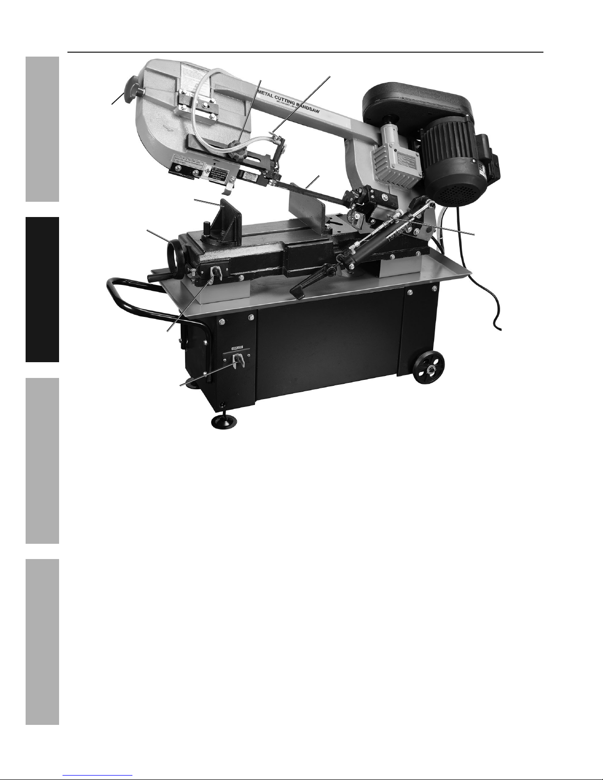
<'84$"&8#
WG@X6%
A6E?CRE6;
?@U%
WG@X6
SRU6;%
?UCATB
!C?6%
B@EX%
UB66G
TRRG@EA%
SFDS%
?UCATB
DR!6@WG6%
!C?6%SG@A6
<66X%
TQGCEX6;%
TREA;RG?
@XcF?A@WG6%
WG@X6%VFCX6%
`ERW
TRRG@EA%
!@G!6

Page 9<&(%$*4.8"4,7%H'*#$"&8#I%/7*,#*%4,77%JKLLLKLMMKNOPO1Item 63469
?@<6AQRS6;@ACRED@CEA6E@ET6 ?6AFS
R/*(,$"83%C8#$('4$"&8#
% ;*,9%$.*%6EAC;6%CDSR;A@EA%?@<6AQ%CE<R;D@ACRE%#*4$"&8%,$%$.*%+*3"88"83%&2%$."#%
5,8',7%"847'9"83%,77%$*b$%'89*(%#'+.*,9"83#%$.*(*"8%+*2&(*%#*$%'/%&(%'#*%&2%$."#%/(&9'4$1
A&&7%?*$%F/
AR%S;6!6EA%?6;CRF?%CEcF;Q%<;RD%@TTCX6EA@G%RS6;@ACRE-%
A'(8%$.*%S&)*(%?)"$4.%&2%$.*%$&&7%&22%,89%'8/7'3%$.*%$&&7%2(&5%"$#%*7*4$("4,7%&'$7*$%
+*2&(*%/*(2&(5"83%,8>%/(&4*9'(*%"8%$."#%#*4$"&81
AR%S;6!6EA%?6;CRF?%CEcF;Q-%
XR%ERA%RS6;@A6%UCAB%@EQ%VF@;X%XC?@WG6XI%X@D@V6XI%R;%;6DR!6X1%%
D&Y"83%3',(9#%5'#$%5&Y*%2(**7>%,89%47&#*%"8#$,8$7>1
A&%C8#$,77%$.*%?,)%W7,9*
T@FACREd To prevent injury from the
Saw Blade (251), wear heavy duty work gloves
during blade installation and replacement.
1. Turn the Cylinder′s Feed Lock on and raise
the Saw Head to its full vertical position. Then
turn the Cylinder′s Feed Lock off to lock the
Saw Head in place. (See Figure C.)
2. Open the Blade Back Cover (286S).
3. Release Saw Blade tension by turning
the Blade Tension Knob (245).
4. Slip the old Saw Blade off the Idler Wheel (250S),
Drive Wheel (231S), and Guide assemblies.
5. Place the new Saw Blade between each of the
Guide assemblies and around the Idler Wheel
and Drive Wheel. CDSR;A@EA-%A.*%$**$.%5'#$%
+*%/&"8$"83%9&)8),(9%$&),(9%$.*%D&$&(1
WG@X6%A6E?CRE%
`ERW
CXG6;%
UB66G
FSS6;%
VFCX6%
@??Q1
GRU6;%
VFCX6%
@??Q1
X;C!6%
UB66G
?@U%
WG@X6
WG@X6%
W@T`%
TR!6;
<"3'(*%T
ERA6-%The Band Saw is equipped with a 93″ long,
0.031″ thick, 3/4″ wide, 6 teeth per inch (TPI) Saw
Blade. Depending on material to be cut, thickness of
material, preference and wear, replace the blade. Please
refer to blade supplier literature, plus woodworker and
metal worker magazines and websites for selection.
T@FACREd If the teeth of the Saw Blade are so far
apart that they straddle the workpiece, severe damage
to the workpiece and/or Saw Blade will result.
6. Tighten the new Saw Blade by turning the
Blade Tension Knob in a clockwise direction.
7. Close the Blade Back Cover.
Page 10 <&(%$*4.8"4,7%H'*#$"&8#I%/7*,#*%4,77%JKLLLKLMMKNOPO1 Item 63469
?@<6AQ RS6;@ACRE D@CEA6E@ET6?6AFS
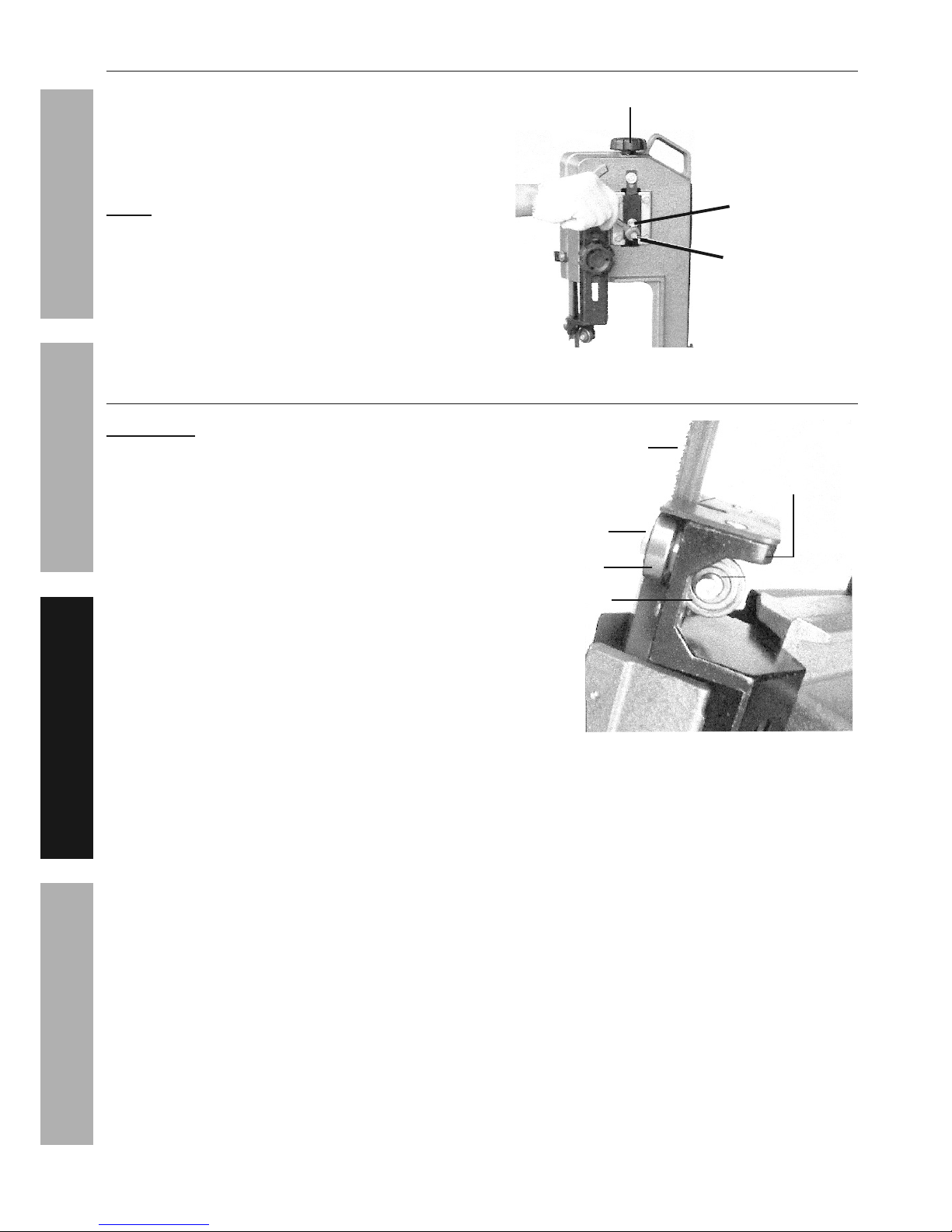
A&%@9='#$%A.*%W7,9*%A*8#"&8
Turn the Blade Tension Knob (245) clockwise to
increase tension on the Saw Blade (251). Turn the
Knob counterclockwise to decrease tension on the
Saw Blade. Correct tension is acquired when the
Saw Blade does not slip on the Drive and Idler wheels
(231S and 250S). (See Figure D and Figure C.)
ERA6- When the Bandsaw is not in use over long
periods of time, release the tension on the Saw Blade.
WG@X6%A6E?CRE%
`ERW
@XcF?ACEV%
B6Z%B6@X%?T;6U
B6Z%B6@X%
?T;6U
<"3'(*%X
A&%@9='#$%A.*%W7,9*%V'"9*%W*,("83#
CDSR;A@EA- Blade Guide Bearings (266-10)
adjustment is a critical factor in the performance
of the Bandsaw. Replace the Saw Blade (251)
to see if it will correct poor cutting quality before
adjusting the Blade Guide Bearings. For example,
if a Saw Blade becomes dull on one side sooner
than the other, it will begin cutting crooked.
Replacing the Saw Blade will correct this problem,
but adjusting the Blade Guide Bearings will not.
1. If a new Saw Blade does not correct the problem,
check the clearance between the Saw Blade and
Blade Guide Bearings to obtain proper clearance.
There should only be a maximum of 0.001 clearance
between the Saw Blade and Blade Guide Bearing.
To obtain this clearance, adjust as follows:
2. The Blade Guide Bearings (266-10) are
mounted to the Guide Pivot Assemblies (270S)
and can be adjusted. (See Figure E.)
3. Loosen the Hex Socket Head Screw (269-9)
while holding the Guide Pivot Assembly
with a hex key (not included).
4. Position the Guide Pivot Assembly by turning
it to the desired position of clearance. Then
re-tighten the Hex Head Socket Screw.
5. Adjust the second Blade Guide
Bearing in the same manner.
?@U%WG@X6
B6Z%?RT`6A%B6@X%
?T;6U
WG@X6%VFCX6%
W6@;CEV
WG@X6%VFCX6%
W6@;CEV
VFCX6%SC!RA%
@??Q1
<"3'(*%6
 Loading...