


(without price)
JY-70B |
(NTSC M / M) |
JY-70C |
(PAL B / G,H) |
JY-70I |
(PAL B / G) |
JY-70N |
(PAL B / G,H) |
(KX-516) |
|
JUL. 1998
INDEX
R
CONTENTS
|
Page |
SPECIFICATIONS ..................................................................................... |
1 |
BLOCK DIAGRAM .................................................................................... |
2 |
PRINTED CIRCUIT BOARDS ................................................................... |
3 |
PARTS LIST .............................................................................................. |
7 |
EXPLODED VIEW ................................................................................... |
11 |
SCHEMATIC DIAGRAMS ....................................................................... |
12 |
WAVEFORMS ......................................................................................... |
16 |
SPECIFICATIONS
|
|
|
Item |
|
|
|
|
Specification |
|
|||
|
|
|
|
|
|
|
|
|
|
|
|
|
|
1. |
Power voltage |
|
|
|
DC 6.0 V |
|
|
|
|
||
|
|
|
|
|
|
|
|
|
|
|
|
|
|
|
|
|
|
|
|
JY-70B |
|
Approx. 3.6 W |
|
||
|
2. |
Power consumption |
|
|
|
|
|
|
|
|||
|
JY-70C/N/I |
|
Approx. 3.3 W |
|
||||||||
|
|
|
|
|
|
|
|
|
||||
|
|
|
|
|
|
|
|
|
|
|
|
|
|
|
|
|
|
|
|
JY-70B |
|
Approx. 600 mA |
|
||
|
3. |
Current consumption |
|
|
|
|
|
|
|
|||
|
JY-70C/N/I |
|
Approx. 550 mA |
|
||||||||
|
|
|
|
|
|
|
|
|
||||
|
|
|
|
|
|
|
|
|
|
|
|
|
|
|
|
|
|
|
|
JY-70B |
|
Approx. 3.5 hours |
|
||
|
4. |
Battery life (with alkaline batteries) |
|
|
|
|
|
|
|
|||
|
JY-70C/N/I |
|
Approx. 4.0 hours |
|
||||||||
|
|
|
|
|
|
|
|
|
||||
|
|
|
|
|
|
|
|
|
|
|
|
|
|
|
|
|
|
|
|
Batteries |
: 4 × LR6 (D) size batteries |
|
|||
|
5. |
Power supply |
|
|
|
Car adaptor : CA-K65 |
|
|
||||
|
|
|
|
|
|
|
AC adaptor |
: AD-K64 |
|
|
||
|
|
|
|
|
|
|
|
|
|
|
|
|
|
|
|
|
|
|
|
Earphone jack |
: 3.5 ø mini |
|
|||
|
|
|
|
|
|
|
External power jack |
: 6.0 V DC IN |
|
|||
|
6. |
Connection terminal |
|
|
|
|
|
|
|
|||
|
|
|
|
|
|
|
External antenna jack |
: 3.5 ø mini |
|
|||
|
|
|
|
|
|
|
(only JY-70C) |
|
|
|||
|
|
|
|
|
|
|
Audio / Video jack |
: 3.5 ø mini |
|
|||
|
|
|
|
|
|
|
|
|
|
|
|
|
|
7. |
Screen size |
|
|
|
2.3 inches |
|
|
|
|
||
|
|
|
|
|
|
|
|
|
|
|
||
|
8. |
Number of picture elements |
|
39,600 (360 × 110) dots |
|
|||||||
|
|
|
|
|
|
|
|
|
|
|
|
|
|
9. |
Dimension |
|
|
|
126 mm (W) × 39 mm (D) × 78 mm (H) |
|
|||||
|
|
|
|
|
|
|
|
|
|
|
|
|
|
10. |
Weight |
|
|
|
Approx. 220 g without batteries |
|
|||||
|
|
|
|
|
|
|
|
|
|
|
|
|
|
|
|
|
|
|
|
|
|
|
|
||
|
Model |
|
Color System |
|
TV System |
|
|
|
Channel |
|
||
|
|
|
|
|
|
|
|
|
|
|
||
|
JY-70B |
|
NTSC |
|
|
M/M |
|
US |
VHF: 2 ~ 13 ch |
UHF: 14 ~ 69 ch |
||
|
|
|
|
|
|
|
|
|
|
|
||
|
JY-70C/N |
|
PAL |
|
|
B/G,H |
|
CCIR |
VHF: 2 ~ 12 ch |
UHF: 21 ~ 69 ch |
||
|
|
|
|
|
|
|
|
|
|
|
||
|
JY-70I |
|
PAL |
|
|
B/G |
|
ITALY |
VHF: A ~ H2 ch |
UHF: 21 ~ 69 ch |
||
|
|
|
|
|
|
|
|
|
|
|
|
|
— 1 —
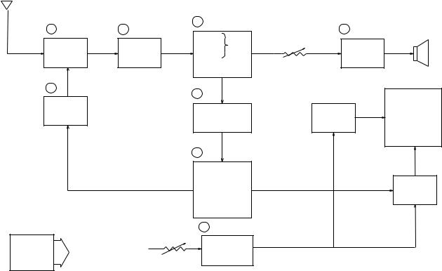
BLOCK DIAGRAM
Antenna
|
|
|
3 |
IC200 |
4 |
IC600 |
Speaker |
1 |
TU200 |
2 |
Q200 |
Video |
|||
|
|
|
|
VR600 |
|
|
|
|
|
|
|
Sound Det. |
Audio |
|
|
|
|
|
|
|
|
||
|
Tuner |
|
IF Amp. |
FM |
|
Amp. |
|
|
|
|
|
AFT Circuit |
Volume |
|
|
|
|
|
|
AGC Circuit |
Control |
|
|
7 |
IC500 |
IC300 |
|
|
|
|
5 |
|
|
||
Tuning |
|
|
|
||
Voltage |
Chroma |
Common |
LCD |
||
Generator |
Circuit |
Driver |
|||
|
|||||
|
6 |
IC700 |
|
|
|
|
|
Osc. |
|
|
|
|
|
Display |
|
Segment |
|
|
|
Control |
|
||
|
|
A-D Converter |
|
Driver |
|
|
|
Auto-Tuning |
|
|
|
|
|
Control |
|
|
|
|
VR800 |
8 Q800 ~ Q803, Q805, Q806 |
|
|
|
|
Display |
|
|
||
Power |
VCC2 (3.95 ± 0.02 V) |
|
|
||
VCC7 (34.2 ~ 41.8 V) |
Voltage |
|
|
||
Supply |
|
|
|||
VEE1 (– 6.03 ~ – 7.37 V) Brightness |
Generator |
|
|
||
|
Control |
|
|
|
|
1— Color Tuner: TU200 TEAA1(JY-70B) / TEPE5-01(JY-70C/N/I) Selects a desired radio wave and changes it to the video IF signal.
2 — Video IF Amp.: Q200 2SC3082
Amplifies the video IF signal output from the tuner TU by 10 times (20 dB).
3 — Video Det./Sound Det./FM Det./AFT/AGC: IC200 M51348FP
Eliminates the carrier wave in the video IF signal, and picks up the video signal and the sound IF signal. Also, the sound signal is picked up from the sound IF signal by FM detection.
4— Audio Amp.: IC600 NJM2070M Sound amplification.
5 — Chroma Circuit: IC300 M52042FP
Generates the tricolor (red, green, and blue) from the video signal.
6 — Osc./A-D Converter/Display Control/ Auto-Tuning Control : IC700 ML9661GA-6006 Converts the color signal into a digital signal.
Also, generates the clock pulse for the display and controls the display.
7 — Tuning Voltage Generator: IC500 BA10358F
Generates the tuning voltage with the tuning pulse (TU) output from 6.
8— Display Voltage Generator: Q800 ~ Q803 Q805 Q806 2SD1819A, 2SB1218A, 2SD1149S Generates the display voltages V0 ~ V4 with VEE1 and VCC7 outputs from the power supply.
—2 —

PRINTED CIRCUIT BOARDS
AD-PCB(JY-70B/C/N/I)
Top View
Bottom View
— 3 —
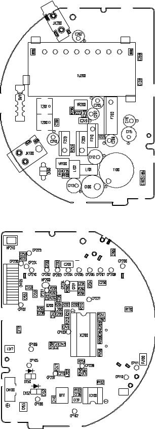
L-PCB(JY-70B)
Top View
Bottom View
— 4 —
 Loading...