


HS-3000-4M

HS-3000/4M
386 ISA Bus SBC
•
CRT/Panel
•
RS-232/422/485
•
4 COM
•
•PC/104•DOC•WDT•Single +5V•
ISA Bus Industrial Single Board Computer
C
C
C
o
o
o
p
p
p
y
y
y
r
r
r
i
i
i
g
g
g
h
h
h
t
t
t
D
D
D
i
i
i
s
s
s
c
c
c
l
l
l
a
a
a
i
i
i
m
m
m
e
e
e
r
r
r
s
s
s
The accuracy of contents in this manual has passed thorough checking and review
before publishing. BOSER Technology Co., Ltd., the manufacturer and publisher, is
not liable for any infringements of patents or other rights resulting from its use. The
manufacturer will not be responsible for any direct, indirect, special, incidental
or consequential damages arising from the use of this product or
documentation, even if advised of the possibility of such damage(s).
This manual is copyrighted and BOSER Technology Co., Ltd. reserves all
documentation rights. Unauthorized reproduction, transmission, translation,
and storage of any form and means (i.e.,
electronic, mechanical, photocopying,
recording) of this document, in whole or partly, is prohibited, unless granted
permission by BOSER Technology Co., Ltd.
BOSER Technology Co., Ltd. reserves the right to change or improve the
contents of this document without due notice.
BOSER Technology Co., Ltd.
assumes no responsibility for any errors or omissions that may appear in this
manual, nor does it make any commitment to update the information contained
herein.
T
T
T
r
r
r
a
a
a
d
d
d
e
e
e
m
m
m
a
a
a
r
r
r
k
k
k
s
s
s
BOSER is a registered trademark of BOSER Technology Co., Ltd.
ISB is a registered trademark of BOSER Technology Co., Ltd.
Intel is a registered trademark of Intel Corporation.
Award is a registered trademark of Award Software, Inc.
AMI is a registered trademark of AMI Software, Inc.
All other trademarks, products and or product names mentioned herein are
mentioned for identification purposes only, and may be trademarks and/or
registered trademarks of their respective companies or owners.
© Copyright 2004 BOSER Technology Co., Ltd.
All Rights Reserved.
Edition 1.6 August 05, 2004

Table of Contents
Chapter 1 General Description..............................1
1.1
Major Features.................................................................. 2
1.2 Specifications ................................................................... 3
1.3 Board Dimensions............................................................ 4
Chapter 2 Unpacking .............................................5
2.1
Opening the Delivery Package........................................ 5
2.2 Inspection.......................................................................... 5
Chapter 3 Hardware Installation ..........................7
3.1 Before Installation ............................................................ 7
3.2
Board Layout .................................................................... 8
3.3
Jumper List ....................................................................... 9
3.4 Connector List .................................................................. 9
3.5
DiskOnChip
Address Setting ..................................... 10
3.6 Watchdog Timer ............................................................. 10
3.7 VGA Controller................................................................ 12
3.8
Serial Port Connectors .................................................. 17
3.9
Keyboard & Mouse Connector...................................... 18
3.10 Speaker Connector ........................................................ 19
3.11 PCI E-IDE Drive Connector............................................ 20
3.12
Parallel Connector.......................................................... 21
3.13 Power and LED Connectors .......................................... 21
3.14 Floppy Disk Drive Connector ........................................ 22
3.15 Flash ROM Type ............................................................. 23
3.16
System Memory.............................................................. 23
3.17 PC/104 Bus Connection................................................. 23

Chapter 4 AMI BIOS Setup.................................27
4.1 Starting Setup ................................................................. 27
4.2 Using Setup..................................................................... 28
4.3
Main Menu ....................................................................... 29
4.4 Standard CMOS Setup ................................................... 30
4.5 Advanced CMOS Setup ................................................. 31
4.6 Advanced Chipset Setup ............................................... 32
4.7
PCI / Plug And Play Setup ............................................. 33
4.8 Peripheral Setup............................................................. 34
4.9 Auto-Detect Hard Disks ................................................. 35
4.10
Change Supervisor/User Password ............................. 36
4.11
Auto Configuration with Optimal Settings................... 37
4.12 Auto Configuration with Fail Safe Settings ................. 38
4.13 Save Settings and Exit................................................... 39
4.14
Exit Without Saving........................................................ 40

S
S
S
a
a
a
f
f
f
e
e
e
t
t
t
y
y
y
I
I
I
n
n
n
s
s
s
t
t
t
r
r
r
u
u
u
c
c
c
t
t
t
i
i
i
o
o
o
n
n
n
s
s
s
Integrated circuits on computer boards are sensitive to static electricity.
To avoid damaging chips from electrostatic discharge, observe the
following precautions:
Do not remove boards or integrated circuits from their anti-static
packaging until you are ready to install them.
Before handling a board or integrated circuit, touch an unpainted portion
of the system unit chassis for a few seconds. This helps to discharge any
static electricity on your body.
Wear a wrist-grounding strap, available from most electronic component
stores, when handling boards and components. Fasten the ALLIGATOR
clip of the strap to the end of the shielded wire lead from a grounded
object. Please wear and connect the strap before handle the
HS-3000/4M to ensure harmlessly discharge any static electricity
through the strap.
Please use an anti-static pad when putting down any components or
parts or tools outside the computer. You may also use an anti-static bag
instead of the pad. Please inquire from your local supplier for additional
assistance in finding the necessary anti-static gadgets.
NOTE: DO NOT TOUCH THE BOARD OR ANY OTHER SENSITIVE
COMPONENTS WITHOUT ALL NECESSARY ANTI-STATIC
PROTECTION.

This page is intentionally left blank.
1
Chapter 1
General Description
The HS-3000/4M is ISA Bus ALi M6117C chipset industrial single
board computer. The board design combine together with all necessary
input and output effects interfaces which makes it an ideal all-in-one
industrial single board computer. The board design with 40MHz Bus
clock rate architecture. The HS-3000/4M supports one SIMM socket
with a max. capacity of 16MB and 4MB RAM onboard.
The IDE interface with LBA mode access to IDE drive interface
architecture, supports with max. 11MB/sec in a data transfers rating to
two IDE drive connection. One set of PC/104 Bus connector for 16-bit
ISA Bus.
A single Flash chip holds the system BIOS, and you can change the
Flash BIOS by the Utility Update. You can also use the DOS version of
the "DiskOnChip" socket by issuing commands from the DOS prompt
without the necessity of other software supports up to 288MB.
2
The board design with 65545 CRT/Panel display controller provides
internal connections to CRT or Panel. The VGA provides up to 1024 x
768 x 16 colors resolution.
If a non-expect program cause halts, the onboard Watchdog Timer
(WDT) will automatically reset the CPU or generate an interrupt. The
WDT is designed with pure hardware and doesn’t need any arithmetical
functions of a real-time clock chip. This ensures the reliability in an
unmanned or standalone system.
1.1 Major Features
The HS-3000/4M comes with the following features:
Intel
®
386SX compatible CPU
One SIMM socket with a max. capacity of 16MB and 4MB RAM onboard
ALi M6117C system chipset
SMC 37C669 super I/O chipset
C&T 65545 CRT/Panel display controller
Four COM connectors
PC/104 Bus connector
DiskOnChip
TM
socket supporting memory sizes of up to 288MB
Single +5V power in

3
1.2 Specifications
CPU: 386SX-40 embedded in ALi M6117C chipset
Bus Interface: ISA Bus
Memory:
One SIMM socket with a max. capacity of 16MB and 4MB RAM
onboard
Chipset: ALi M6117C
I/O Chipset: SMC 37C669 x 2
VGA: C&T 65545 with 1MB memory supporting CRT/Panel displays up
to 1024 x 768 at 16 colors
IDE:
Two IDE disk drives supporting LBA mode and with a transfer rate
of 11MB/sec.
FDD: Supports up to two floppy disk drives
Parallel: One enhanced bi-directional parallel port supporting SPP/ECP/
EPP
Serial Port: 16C550 UART-compatible RS-232/422/485 x 1 and RS-232
x 3 serial ports with 16-byte FIFO
PC/104: PC/104 connector for 16-bit ISA Bus
Keyboard: PS/2 6-pin Mini DIN or 5-pin connector
Mouse: PS/2 6-pin Mini DIN
DiskOnChip
TM
: DiskOnChip
TM
socket supporting memory sizes of up to
288MB
BIOS:
AMI PnP Flash BIOS
Watchdog Timer:
Sets 1/2/10/20/110/220 seconds activity trigger with
Reset or NMI
CMOS: DS12C887 or equivalent device
Power: Single +5V/1.8A power in
Power Connector: One 4-pin +5V/+12V power connector
Temperature: 0~60°C (operating)
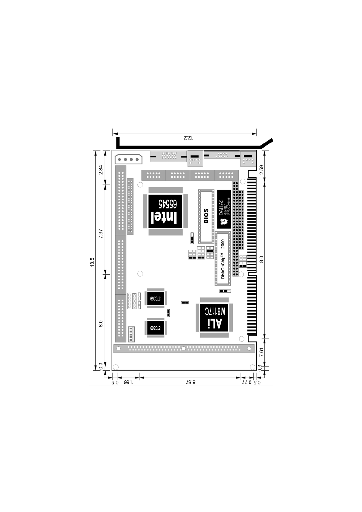
Dimensions: 18.6 x 12.2 cm
4
1.3 Board Dimensions

5
Chapter 2
Unpacking
This chapter explains unpacking the board, checking the equipment
and documentation and where to go from there.
2.1 Opening the Delivery Package
The HS-3000/4M is packed in an anti-static bag. The board has
components that are easily damaged by static electricity. Do not
remove the anti-static wrapping until proper precautions have been
taken. Safety Instructions in front of this manual describe anti-static
precautions and procedures.
2.2 Inspection
After unpacking the board, place it on a raised surface and carefully
inspect the board for any damage that might have occurred during
shipment. Ground the board and exercise extreme care to prevent
damage to the board from static electricity. Integrated circuits will
sometimes come out of their sockets during shipment. Examine all
integrated circuits, particularly the BIOS, processor, memory modules,
ROM-Disk, and keyboard controller chip to ensure that they are firmly
seated. The HS-3000/4M delivery package contains the following
items:
HS-3000/4M Board x 1
IDE port flat cable x 1
FDD port flat cable x 1
Printer + one COM flat cable with bracket x 1
Two COM flat cable with bracket x 1
Utility CD Disk x 1
User’s Manual x 1

6
It is recommended that you keep all the parts of the delivery package
intact and store them in a safe/dry place for any unforeseen event
requiring the return shipment of the product. In case you discover any
missing and/or damaged items from the list of items, please contact
your dealer immediately.

7
Chapter 3
Hardware Installation
This chapter provides the information on how to install the hardware
using the HS-3000/4M. This chapter also contains information related
to jumper settings of switch, watchdog timer, and the DiskOnChip
address selection etc.
3.1 Before Installation
After confirming your package contents, you are now ready to install
your hardware. The following are important reminders and steps to take
before you begin with your installation process.
1. Make sure that all jumper settings match their default settings
and CMOS setup correctly. Refer to the sections on this chapter
for the default settings of each jumper.
2. Go through the connections of all external devices and make
sure that they are installed properly and configured correctly
within the CMOS setup. Refer to the sections on this chapter for
the detailed information on the connectors.
3. Keep the manual and diskette in good condition for future
reference and use.
8
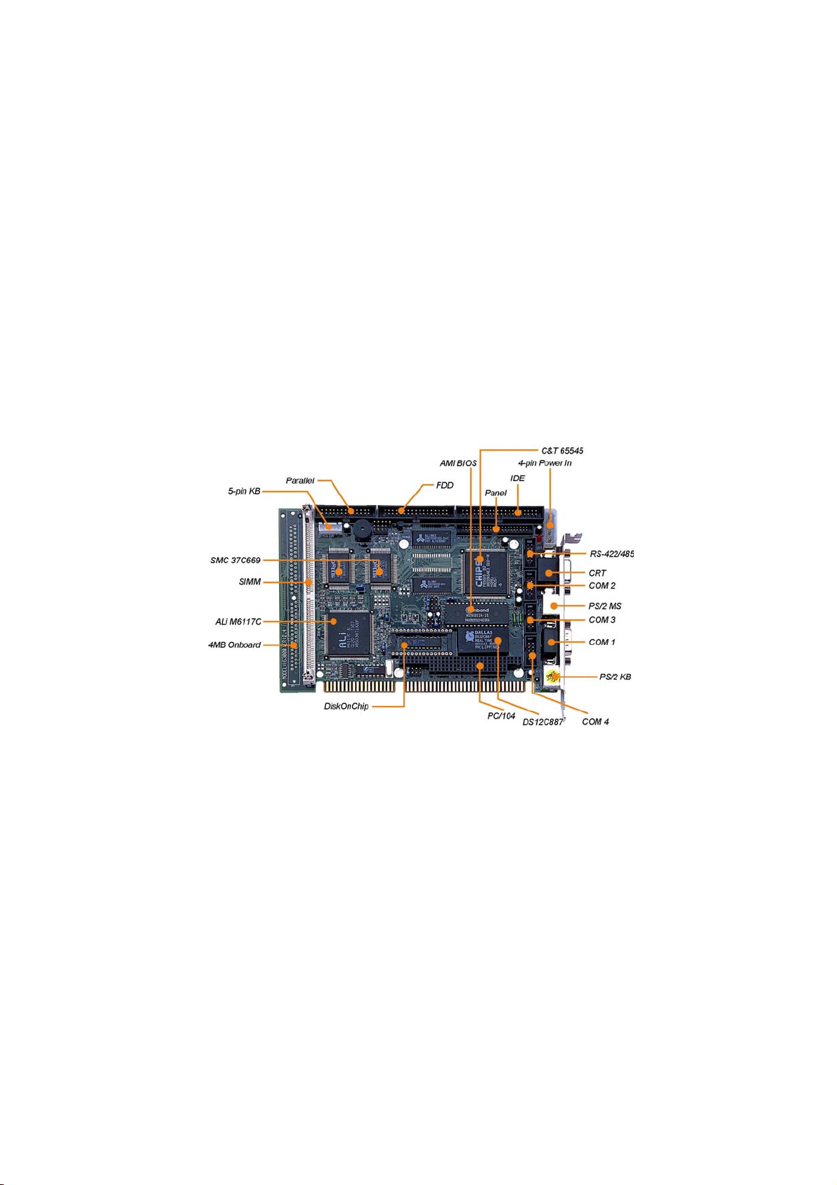
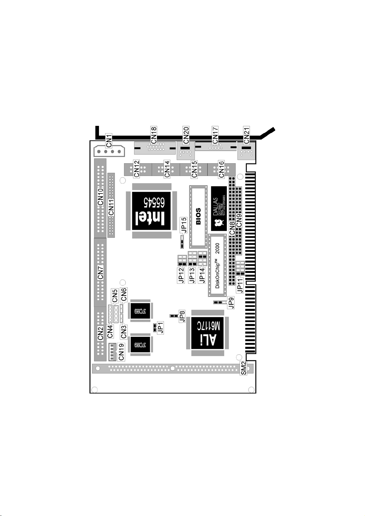
3.2 Board Layout
 Loading...