

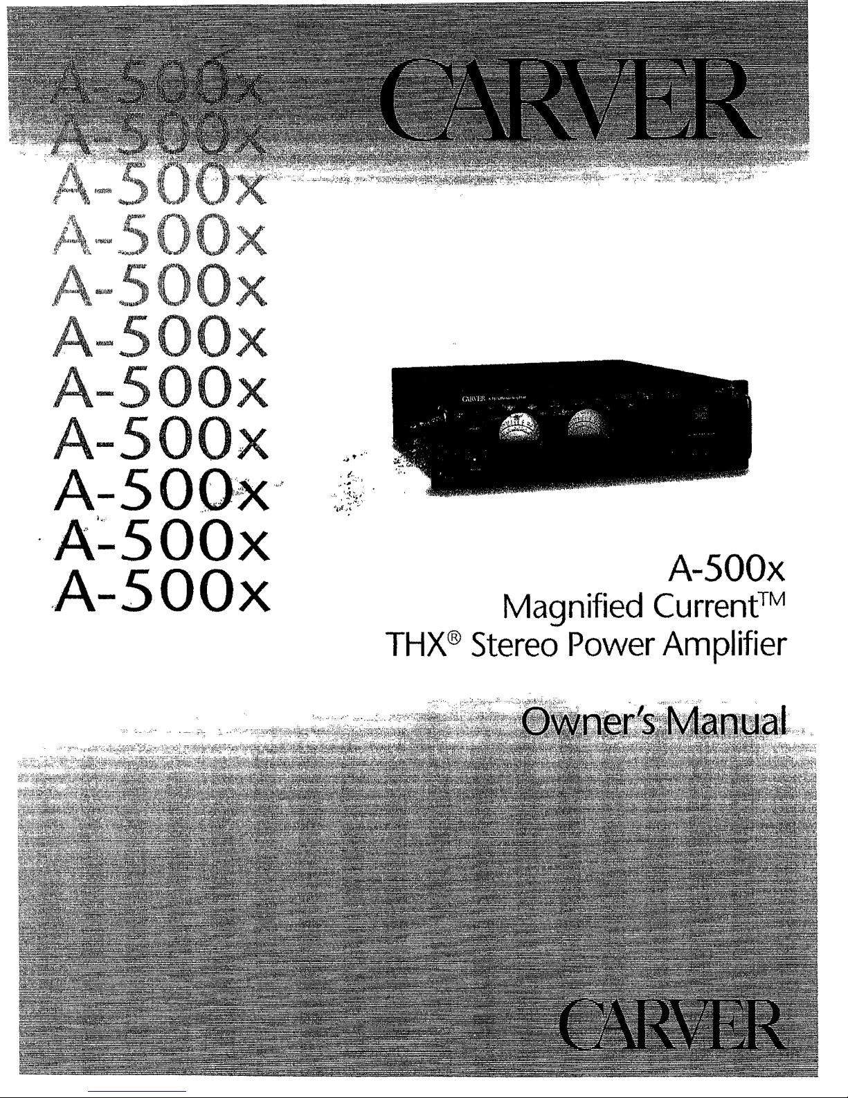
Carver Magnified current A-500 Series Owner's Manual
Ji3!!!l
dw
VJaMOd
Oi3JalS
®XHl
lAJlluaJJn:)
pa!l!
u6E
lAJ
xOOS-v
XOOS-V'
XOOS:V··
~"O·
"·."'-'·0
C
""
Aj;/.,
'.
:J
-
'*-'
V
xOOS-V
XOOS-\t
o

A-500x
1. Safety
Instructions
9.
Power Cord Protection - Power-supply cords should
be
~
rou
ted
so
that they are not likeIy to
be
waI
ked
upon
or pinc
hed
1.
Read Instructions - All the safety and operation
by items placed upon or against them, paying particular
instructions should
be
read
before
the
Carver
Component
attention to
cords
at
plugs,
convenience
receptacles, and the
·"··'·
..
'.'·"·.I'.:•.'··
~.-.)
•.
"·.".:.
;:
is operated.
2.
Retain Instructions -
The safety and operating
instnlctions should be kept
for
future reference.
3.
Heed Warnings -
All
warnings
on
the
Compo
..
nent and
in
these operating
instnlctions should
be
followed.
4.
Follow
Instructions-
All
operating
and
other
instructions should be
followed.
5.
Water and
Moisture-
The
Component should
not
be used near water
...
for example, near a
bathtub, washbowl,
kitchen sink, laundry tub
t
in
a wet basement, or near
a s\vimming pool, etc.
6.
Ventilation - The
Component
should
be
situated so that its
location or position does
not interfere with its
proper ventilation. For
examplef the
Component
should not be situated
on
a bed,
sofat rug,
or
similar
surface that
may
block
any ventilation openings;
or placed
in
a built-in
installati0 n such
as
a
bookcase or cabinet that
may
impede
the
flow
of
air through ventilation
openings.
7.
Heat - The Compo-
'.~::,,:
point
where
they exit
the
Component.
~
10,
Cleaning -
The
Component should
be
cleaned only as
recommended in this
manual.
I~'-'--
..
f:.{"
I~··il;l
..
:
,.:.!~
..
~
11.
Non-use
Periods-The
power cord ·of the
Conlpo~
(Li'
nent
should be unplugged
~
from the outlet when
unused
for
a long period
of time.
12.
Object and Liquid
Entry - Care should
be
taken so that objects
do
not
fall
into
and
liquids
are
not
spilled into
the
inside
of
the Component.
~:,7i
';·v.~:
~;'4)'~~i
I
13.
Damage Requiring
~
Service - The Compo-
nent should
be
serviced
only
by
qualified service
perS0I111e
I w
he
n:
A.
The
power-supply
cord
or
the
plug
has
been
damaged;
or
B. Objects have fallen, or
liquid has spilled into the
Component;
or
C.
The
Component
has
been exposed
to
rain; or
D.
The Component does
not appear to operate
normally or exhibits
a marked change
in
performance;
or
E.
The Component
has
been dropped, or
its
cabinet
damaged~
CAUTION
RISK OF ELECTRIC
SHOCK
DO NOT OPEN
CAUTION:
TO
REDUCE THE RISK OF ELECTRIC SHOCK
DO NOT REMOVE COVER (OR BACK)
NO
USER..SERVIC'EABLE
PARTS
INSIDE
REFER SERVICING
TO
QUALIFIED SERVICE PERSONNEL
The lightning flash
with
arrowhead
symbol
within an equilateral triangle is intended to
arert
the user
to
the
presence of uninsulated
Udangerous
voltage" within the
product1s
encJosure~
that may
be
of
sufficient magnitude
to constitute a risk of electric shock to
persons~
The exclamation
point
withjn
an
equilateral
tri
angle
is
intended
to
alert the user
of
the
presence
of
important operating
and
main
...
tenance (servicing) instructions
in
the literature
accompanying
the
appliance.
PORTABLE CART WARNING
Carts
and
stands
..
The
Component should
be
used
only with a cart
or
stand
that
is
recommended by
the
manufacturer.
A Component and cart
combination should
be
moved with care. Quick
stopSt
excessive force, and
uneven
surfaces
may
cause
the Component and cart
combination to overturn.
nent should be situated away from heat sources such
as
14.
Servicing - The user should not attempt
to
service the
radiators} or
other
devices which produce heat.
Component beyond those means described
in
this
operating
8. Power Sources -
The
Component
should
be
connected
manual. All other servicing should
be
referred
to
qualified
to a po
wer supply only
of
the
type described
in
these
service personneL
operation instructions or as
marked
on
the
Component
It
15.
To
prevent electric shock
t
do
not use this polarized plug
with
an
extension
cord,
receptacle
or
other
outlet
unless the
blades can be
fully
inserted to prevent blade exposure.
Pour preevenir les chocs electriques ne pas utiliser cette
fiche polarisee avec
un
pro}ongateur, un prise de courant
ou une autre sortie
de
courant,
sauf si
Ies
1ames
peu
ven
t
etre inserees afond sans laisser aucune pariie adecouvert.
16. Grounding
or
Polarization
-..
Precautions should
be
taken
so
that the grounding or polarization means of the
Component is not defeated.
17.
Intern
a1lExternal
Voltage
Selectors - Internal or
external line voltage selector switches, if
any,
should only
be
reset and re-equipped
with
a proper plug
for
alternate
vol
tage
by
a qualified service technician.
See
an
Author
..
ized Carver Dealer for
more
information.
<.
.'.'
_..
oX
~,::.::;:
.
~'.."
~.
~:.':
I..
. .
18.
Attachment Plugs for Alternate
Line
Voltage (Dual
voltage models only) -
See
your Authorized Carver
• I
~.:
••
••••
•••
"
. '"
'A';o
-"5""0"0':
:',
",",~'o:;~
Dealer for
information on the attachlnent plug for alternate
voltage use.
This
pertains
to
dual-voltage units
only.
This apparatus does not exceed the Class A/Class B
(whichever
is
applicable) limits for radio
noise
emissions
from digital apparatus as set
out
in the radio interference
regulations of
the
Canadian Department of
Communica-
tions.
ATTENTION - Le
present appareil numerique
n1emet
pas
de bruits radioelectriques depassant las limites applicables
aux
appareils nunleriques
de
class
Aide class B (selon
Ie
cas) prescrites dans
Ie
reglement sur
Ie
brouillage
radio61ectrique edicte par les
ministere des communications
du Canada.
WARNING -TO
REDUCE
THE
RISK
OF
FIRE
OR
ELECTRIC
SHOCK,
DO NOT EXPOSE THIS APPLIANCE TO RAIN OR MOISTURE.
CAUTION:
TO
PREVENT
ELECTRIC
SHOCK,
MATCH
WIDE
BLADE
OF PLUG
TO
WIDE
SLOT,
FULLY
INSERT.
ATTENTION:
POUR
EVITER
LES CHOCS
ELECTRIQUES,
INTRO-
DUIRE LA
LAME
LA PLVS LARGE
DE
LA FICHE
DANS
LA BORNE
CORRESPONDANTE
DE
LA
PRISE
ET
POUSSER
JUSQU'
AU
FOND.
Contents
1. Safety Instructions
~
+.It
••••••••••
t t
•••••••• ~ •••••••••••.•••••••••••
2
2.
Prelude , 4
3.
Fea,tures
and
Specifications 61' , , ,
••
4.
Unpacking
and
Paperwork 7
5.
Installation , 8
l
..
ocation
and
General Precautions 8
Handle Removal
""
..
~
8
AC
Power Considerations , 9
Connection
Tips
~
9
Rear Panel
Connections
and
Controls
9n
6.
Operation
~ ~
, 10
Front
Panel Features 10
System
Configurations
12
A qUick
note
on
input/output
levels " 17
Amp-to.Preamp
Connections
17
Amp-to-Speaker
Connections
,
17
Wiring
.,
,
"'
17
Hook-up
~
17
Stereo Operation
~
18
Mono
Operation
~
"
18
Amplifier
Protection
19t
Speaker
Protection
19
7..
In
Case
of
Difficulty 21t
8. Care
and
Service Assistance , ,
~
23t
e
..
·:'···;'·/;A"·'"
':~.:',
'.s'"
0'"
0·' . '.
'<.~.:.:;",.'
".~'~~"'-:.
"..
'.
x .
I
•• -:••••
: I •
~:
;
•••
_ I ' - •
~",
_
-.,
2. Prelude
Your
new
Carver
Magnified
Current™
THX
Power
Amplifier carries
with
it a
heritage of over 15 years
of
audio
research,
development
and
design
refinements.
Carver engineers
make
use
of
the
latest
advances
in
electronics
ma·nufacturing
techniques
to
provide
state
..
of-the-art
high-value audio
products
which
empha-
size
innovative
technologies
and
features
at
an
affordable price.
An
American
electronics
innovator
based
in
the
Pacific Northwest,
Carver
began
in
the
early 80s
with
a series
of
product
successes
such
as
the
C-4000
preamplifier
with
Auto-Correlator™
and
Sonic
Holography'11vi,
the
TX-l1
tuner
with
ACCDTM
(Asymmetrical
Charge-Coupled
Detector)
and
the
M-l.S
stereo
power
amplifier,
one
of
the
most
powerful ampli-
fiers available
at
tile
time
for
home
hi
..
fi
uset
.As
technology
has
evolvedt so have
Carver's products.
In
fact, a
number
of
audio technologies an·d features consid-
ered
standard
today-
including
surround-
sound
and
advanced
signal
processing-
had
their
first successful
consumer
appli
w
cations
in
a Carver component! Many
Carver
products
are
now
considered
"clas-
sics",
and
most
are still
in
use
with
their
original
owners
who
routinely upgrade
their Carver-based systems
rather
than
replace
them.
As
it
has
since
our
company!s
beginning,
the
Carver
name
remains
synonymous
with
leading
edge
technology
expressed
in
audio
compo-
nents
that
never
become
obsolete.
At
Carvers
technology
is
regarded
as
a
tool
used for
one
purpose:
to
advance
the
science
of
reproducing
sound
in
the
home. Every
Carver
employee
has
this
common
goal,
from
our
CEO
and
Board
of
Directors,
our
Engineering,
Sales
and
Marketing,
Accounting
and
Finance,
Customer
Service
and
Technical
SUPJ?ort
Staff
to
the
Manufacturing
and
QualIty
Control
people
who
actually
put
the
products
together
here
in
Lynnwood,
Washington.
We love
home
entertain-
ment.
The
vigilant
pursuit
of
I?roviding
0,
quality
and
reliable
products
aImed
at
reproducing
audio
with
absolute
accuracy
-
whether
it
be
from
a treasured
I.,P
vinyl
recording
or
the
digital
formats
of
tomor-
row -is
our
corporate
vision.
To
this end,
the
A-SOOx
was developed
with a number
of
important design
fea
..
tures
and
goals
in
mind.
A power
ampli-
fier
has
only
one
job,
but
a
very
important
one:
amplifying
the
audio
signal
without
being
disturbed by
the
loudspeaker
load.
Ideally,
the
signal
coming
out of an ampli-
fier
should
be
iderttical
in
every
way
ex-
cept
magnitude
to
the
signal
that
went
into
itt
In
realitr'
there
are subtle ways
in
which
the
signa
can
be
changed
by
an
amplifier,
which
are
described by
measure-
ments
such
as
THD, noise,
DC
offset,
crosstalk
and
phase
shift. All
these
techni
..
cal
terms
boil
dow.n
to
one
thing -the
signal
has
been
changed
(distorted)
in
some
way
from
its original
form
by
the
amplifier. I
There
are a
number
of
ways
to
mini-
mize
this
distortion.
One
of
the
most
effective
and
efficient is
to
minimize
the
signal
path~
While
that
may
sound
simple
J
it
is
actually
very
difficult
to
achieve.
OUf
engineers
went
to
great
lengths
to
shorten
the
signal
path
(pun
intended!)
as
much
as
technology
and
physics allow. A
short
signal
path
pre-
vents
corruption
of
the
signal from
the
effects
of
EMI, strayfield
magnetic
radia-
tion
and
cumulative
reactance
in
the
critical signal
conductors.
l~he
result
is
a
much
cleaner
(and
very
nearly
perfect)
reproduction
of
the
signal
at
the
amplifier's
output.
The
A-SOOx
is
rated
conservatively at
250
watts
per
channel
into 8 ohms
and
delivers
over
400
watts
per
channel
into
4
ohms.
It
also
has
the
flexibility
and
power
®
(-
r:':,'·'
L._
L
I.
L
1,."
1'.:
....
:.
L
I·:·:::··
J
I'·
L
k
L
--
reserves
to
become
an
800
watt+
bridged
mono amplifier
when
even
higher
power
levels are needed. This is
an
enormous
am'ount
of
power,
made
possible through
the
development
of a new
multi·state
hybrid power amRlifier design
we
call
Magnifled
Current
. It uses
two
160
amp
peak current
power
MOSFETs
per
channel,
with nanosecond sWitching speed
to
assign twice
the
continuous
voltage
to
the
·
output
stage
when
high
voltages are re-
quired}
or
more
than
twice
the
continuous
Ctlrrent
when
higher
current is needed.
This maximizes
both
the
voltage
and
current
capability (peak
or
continuous)
available for any
loudspeaker
load;
even
thos.e
that
have a substantial
reactive
component
that is difficult for conven-
tional
amplifiers
to
drive.
As
a result
of
this
difficulty
in
driving
demanding
loudspeaker loads,
conven-
tional
amp1ifiers
use
stabilizing
inductors
on
the
output
of
the
amplifier
to
keep
the
amplifier from oscillating
and
even
self-
destructing.
Unfortunately,
these
in·due-
tors also cause low
damping
at
high
fre-
quencies
which
can
create
high
frequency
coloration.
Carver
has
developed
Total
Direct
Coupling™
(TDC)
to
combat
this
problem.
TDC
means
that
the
output
circuitry is
directly
connected
to.
the
loudspeaker
without
the
usual
stabilizin~
inductor
networks
between
the
amplIfier
output
and the loudspeaker termInals. Due
to
the
wide
open
loop
bandwidth,
ideal stability
and
load
immunity
of
the
new
Carver
amplifier module, the traditional sound
altering Ustability
bandaids"
of
conven-
tional
amplifiers are
no
longer
necessary.
This
not
only
cre'ates
a totally stable power
amplifier
into
all speaker loads,
it
also
provides
high
damping
factor
at
all
frequencies-
not
just
i.n
the
bass region.
lUCASFllM
.
.'
··A-500x·:
That
means
full
control
in
th'e bass,
midrange and
high
frequencies.
No
more
harsh
or
rolled
off
highs, just
pure
and
natural clarity from top to bottom.
In
addition
to
new
audio
technologyj
Carver engineers also designed the
A-500x
to
set
new
stand~rds
in
reliability
and
value. The
A-SOOx
makes full
use
of
their
modular
d'esign
philosophy
and
open-
frame
architecture
for efficient
and
cost
...
effective
assembly_
This
has
the
added
benefit
of
providIng
superior
channel
isolation, eliminating the
detrimental
effects
of
interchannel
crosstalk.
The
amplifier's
enclosure
is·
designed
to
pro-
vide
open air access
to
the
heatsinks. This
affords
more
efficient dissipation of
heat
away from
the
triple-diffused
planar
high-
current
output
devices,
which
results
in
greater reliability
and
longevity
of
the
amplifier.
The
THX logo
on
the
front
panel
of
the
Carver
A-SOOx
is
another
important
fea-
ture
of
the
amplifier. THX certification
means
that
the
A-SOOx
meets
a set of strict
performance
standards
which
ensure
that
the
soundtrack's
reproduction
is
faithful
to
the
director's
intent~
The
Carver
A..500x
can
be
used
with
other
THX
certi-
fied
audio
equipment
to
create a
true
Home
TH.X
Audio System.
Other
features are
included
to
provide
convenience
and
flexibility
such
as
vari
...
able
input
sensitivity controls, removable
handles
and
front
panel
analog
meters
with
two
sensitivity settings.
The Carver
A-SOOx
was designed
and
manufactured
by
people
with
a lifetime
commitment
to
providing
the
world's
finest
components
for
sound
reproduction
and
home
entertainment.
Thanks
for
placing
your
confidence
in
Carver. We
know
your
new
amplifier will provide
many
years
of
listening
enjoyment.
If you have
access
to
the
Internet,
you
can
check
out
the
full line
of
Carver
products
and
company
an
..
nouncements
·on
our
World Wide·
Web page (http://www.carver.com).
o.:':'·A··"':··"S:···:'·O'O·
'.-.:
....
I I
•. ~ :.
, .
".~: . ~.
I".
.
~-
,"
.: .., .. > .....
;., ..' :
·X':
'.
~
.,.'.,.,
::
~
\.'
, . . . ,'
r
~;
tr
3. Features and Specifications
~
A-500x Special Features
[
0
250 watts
per
channel
into 8 ohms
o Fully-complementary
differential
cirCllitry
400 watts
per
channel
into
4
ohms
using low-noise,
high
speed transistors
t~;~::'
750
watts
per
channel
into
2
ohms
throughout
lL
(IHF
dynamic
power)
o DC Servo correction using new Texas
800
watts
bridged
mono
into 8
ohms
Instrument
Excalibur™
operating
point
":,".','
a Certified
by
Lucasfilm Ltd. for use
in
controller
1
;~.
Home
THX Audio Systems
~
a Double-stage
ground
isolation system
o Magnified
Current™
technology
for in-
prevents
gro~nd
loops and
RF
inte-rference
creased voltage
and
current
capability
o Triple-diffused
planar
high-current
otttput
l~
L..
o Total Direct Coupling™ for
high
damping
devices
with a cOlnbined
output
safe
factor
at
all frequencies
operating
capability
of
1000
watts
o Each channel
protected
by:
o Dual
analog
lighted
meters
with
range
l
Individual
fusing
selection
switch
DC fault sense
o
Meter
light
On/Off
switch
t:.
Shofted-load sense
Excess
temperature
sense
o
Gold-plated
RCA
input
jacks
~:"
Powerwon delay
o
International
safety
compliant
binding
o Minimal signal
path
design,
with
on-card
posts
k,·
t
I/O
connectors
eliminating
internal
inter-
o Individual calibrated level trim controls for
connect
cables
each
channel
'i-:;::."
0
Precision
passive
components used
in
all
o Removable
handles
for
placement
in
17"
rf~
'if...
critical
signal
paths
(no
electrolytic
capaci
w
wide
cabinet
space (with
trim
end
caps)
tors
in
signal
path)
o Made
in
USA
l
Sp'ecifications
!~""
fe',
Power
Output:
E,
L
Stereo operation:
f~,',
,
Power
FTC
20Hz-20kHz, 8 ohm
250
watts per channel with < 0.08%
THD
Damping Factor:
> 150
l
400 watts per channel into 4 ohms
(20
to 20kHz)
v
750 watts per channel into 2 ohms
t~;~,.
(IHF
dynamic power)
8.
Input Impedance:
47 kohms
Bridged mono operation:
r:
800
watts into 8 ohms
Sensitivity:
~:::.
Per
THX
standard:
L
}';"
Dynamic Headroom:
1.0V rms input for 1
DOW
output into 8 ohms
> 1.0dB @ 8 ohms both channels
drive'n
1.58V
rms
for rated power into 8
ohms
@ 1
kHz
t:::,
I
Frequency Response:
20
Hz
to
20
kHz
Gain:
29.0 dB (+/-
O.5dB)
(+0,-0.2 dB)
F'
k
Input-to-Output
Phase:
0°
(±100)
__
Separation:
> 70
dB
@ 1kHz

1M
Distortion:
SMPTE
<
0.03%
CCIF
<
O~01
%
THO:
< 0.08%
Signal-to-Noise
Ratio: > 117
dB
A-weighted, referenced to rated power
> 93
dBW
A-weighted, referenced
to
1W
Power Consumption:
50W
at
idle
330W
with
musical
program
880W at full
power
into
8 Q (continuous)
Power
Requirements:
120VAC/60Hz
(USA
and
·Canada)
Other voltages as required
for
export
Display:
2 Analog Meters;
OdS
= 250
watts
into 8 n
or
25
watts
into
an
(x10 range)
Size
(H
x W x
D):
5.75'1
x 19·· X
18.8
11
146mm
x 483mm x
478mm
with
handles
5.75" x17
1f
x 17.8"
146mm x 432mm x 452mm
without
handles
Net Weight:
29
Ibs. (13.2 kgs)
Shipping
Weight:
34
Ib·s.
(15.4
kgs)
Features
and
specifications
are
subject
to
change
without
notice.
..
<
A~5()Ox·<'
, .
I.":
,'-
4. Unpacking and
Paperwork
Carefully
unpack
your
A-SOOx
and
keep
the
original carton
and
packin'g materials
for
future
moving,
shipment
or
long-term
storage~
After
opening
the
box, please check for
any
visible signs
of
damage
that
were
not
apparent
from
the
outside
of
the
box.
If you do encoun-
ter what appears
to
be concealed
damage,
please
consult
your
Carver Dealer before
proceeding
to
further
unpack
or
install
the
unit.
Important
Paperwork
Make
sure
to
save
your
sales
receipt.
Your receipt is
extremely
important
to
estab
w
lish
the
duration
of
your
Limited Warranty}
and
for insurance purposes. Next,
make
a
note
of
the
serial
number
which
is located
on
the
back
of
the
amplifier. Record
it
in
the
space
provided below for convenient reference
..
Model: A-500x
Serial
Number:
_
Purchased at:
----0-..----
Date: _
Finally,
take a moment
to
fill
out
the
Cus-
tomer
Registration
Card
packed
with
the
amplifier
and
return
it
to
Carver
..
This allows
us
to
keep you
informed
of
new
products
and
technologies
as
they
become
available.
e
--
L
1"-
~
• • L
'.;
,<
"0"0'
".'
\<::,!A7$
.
••.....•~ •.....
l::~;:,,
t-
L...;.,;,
5.
Installation
Location and General
Precautions
Observe
the
following
precautions
when
choosing a
location
for
the
A-SOOx:
o Do
not
expose
the
unit
to
rain
or
moisture.
o Protect
from
prolonged
exposure
to
direct
sunlight.
o Avoid excessive
exposure
to
extreme
cold
or
dust.
o Do
not
place heavy
objects
on
the
unit.
000
not
place
magnetic
storage
media
suel1 as
audio
or
video
tapes
near
the
amplifier. All
power
amplifiers
con-
tain
transformers
that
are
surrounded
by
a
fluctuating
magnetic
field
which
can
erase
magnetic
tapes
(or
floppy disks).
a Protect
from
heat
and
allow
adequate
ventilation.
Place
away
from
direct
sources
of
heat,
such
as
heating
vents
and
radiators. All
compo-
nents
produce
some
heat
during
operation!
so
make
sure
that
the
ventilation
holes
are
not
covered
and
that
air is
allowed
to
circulate
freely
behind,
beside
and
above
the
unit.
Excessive
heat
is
the
single greatest
source
of
both
short-term
and
long-term
component
failure.
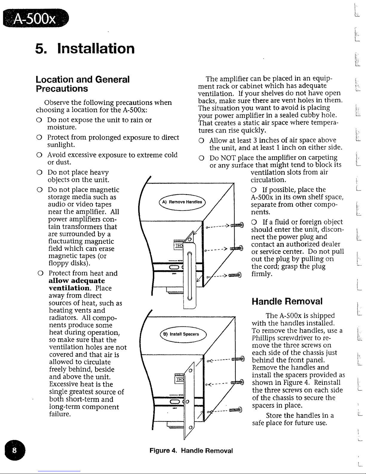
A)
Remove Handles
-----~
B) Install Spacers
The
amplifier
can
be
placed
in
an
equip-
ment
rack
or
cabinet
Wllicll
has
adequate
ventilationQ
If
your shelves
do
not
have
open
backs,
make
sure
there
are
vent
holes
in
them.
The
situation
)'0U
want
to
avoid is
placing
your
power
amplifier
in
a sealed cubby hole.
That
creates a static air space
where
tempera-
tures
can
rise quickly.
o Allow
at
least 3
inches
of
air space above
the
unit}
and
at
least
linch
on
either
side.
o
Do
NOT
place
the
amplifier
on
carpeting
or
any surface
that
might
tend
to
block its
ventilation
slots
from
air
circulation.
o If possible,
place
the
A-SOOx
in
its
own
shelf space,
i
separate
from
other
compo-
l-:-:
5,-_,
nents.
L-
o If a fluid or foreign object
i
should
enter
the
unit
l
discon-
1.
nect
the
power
plllg
and
l
contact
an
authorized
dealer
or
service center.
Do
not
pull
out
the
plug
by
pulling
on
the
cord; grasp
the
pllig
firmly.
-;
1L--
Handle Removal
l-
t
The A..SOOx
is
shipped
with
tIle
h.anciles
installed.
t-
To
remove
the
handles, use a
!'._:
t:
..
>
Phillips screvvdriver to
re~
L::.::..
move
the
three
screws
on
each side of
the
chassis just
1-;-,-
j
behind
the
front
panel.
Remove
the
handles
and
L-
install
the
spacers
provided
as
1--
shown
in
Figure
4.
Reinstall
i
L
the
three
screws
on
each
side
I~
of
the
chassis
to
secure
the
spacers
in
place.
L
Store
the
handles
in
a
safe place for future use.
L-..--
Figure
4.
Handle Removal
1-;.-
 Loading...