

Carver GVC Series, GVT Series Installation, Operation And Maintenance Manual
(GVC) I-460 Rev. 02
(GVT) I-470 Rev. 02

SERVICE RECORD PAGE
Service No. ________________ Size and Type ______________ Make _____ ___________________
Cust. Order No. ________________________ Date Installed ___________ _______________________
Installation Date
Location
Application
PUMP RATING
Capacity (GPM) __________________________ Total Head (ft) _______________________________
Suction Pressure _________________________ Speed (RPM) ________________________________
Liquid __________________________________ Temperature ________________________________
Specific Gravity __________________________ Viscosity ____________________________________
Impeller Diameter (inches) ____________________________ __________________________________
PUMP MATERIALS
Casings ___________________ Impeller ________ ___________ Diffuser _______________________
Shaft ____________________________________ Wear Rin g ________________________________
O-rings _______________________________ Beari ng Frame _______________________________
Mechanical Seal, Suction End (Low Pressure) ______________________________________________
Mechanical Seal, discharge End (High Pressure) ____________________________________________
DRIVER DATA
Motor _________________ Make _______________________ _ Serial No. ______________________
Type __________________ Frame _______________________ AC or DC ______________________
HP ____________________ RPM ________________________ Volts _________________________
Phase _________________ Cycles _______________________

INSPECTION DATE
NOTES ON INSPECTION AND REPAIRS
REPAIR TIME
REPAIRS
COST
REMARKS

TABLE OF CONTENTS
LOCATION/DESCRIPTION PAGE
• SERVICE RECORD PAGE ...............FRONT
• NOTES ON INSPECTION AND
REPAIRS...........................................FRONT
I. GENERAL INFORMATION .........1
A. Preface....................................1
B. Pump Identification .................1
C. Parts Inventory Guide.............1
D. Parts Ordering.........................1
E. Safety Precautions..................1
II. INSPECTION AND STORAGE ...2
A. Inspection Upon Arrival...........2
B. Storage of Pump.....................2
III. INSTALLATION ...........................4
IV. ALIGNMENT................................4
V. OPERATION................................4
A. Prestart Cautions....................4
B. Starting the Pump...................4
C. Stopping the Pump .................4
VI. MAINTENANCE...........................5
A. Field Inspection.......................5
B. Stuffing Box.............................5
C. Bearing Temperature..............5
D. Bearing Lubrication.................5
VII. TROUBLESHOOTING.................6
VIII. SERVICE AND REPAIR..............9
A. Disassembly and Assembly....9
B. Parts Inspection......................14
LOCATION/DESCRIPTION PAGE
C. Adjusting Impeller Clearance
on Pump Equipped with
Semi-Open Impeller................16
D. Replacement of Optional
Wear Ring on Pump Equipped
with Enclosed Impeller............16
IX. PARTS LIST AND FIGURES...... 17
LIST OF TABLES
TABLE TITLE PAGE
A. Recommended Torque Values .....5
1. Troubleshooting ............................7
2. Throttle Bushing Dimensions........ 15
3. Enclosed Impeller Clearance........ 15
4. Impeller/Wear Ring Matching
Materials........................................16
5. Recommended Spare Parts..........17
6. Pump Parts List for GVC 1520 and
GVC 1530/1540 ............................18
7. Pump Parts List for GVT 1520 and
GVT 1530/1540............................. 18
LIST OF ILLUSTRATIONS
FIGURE TITLE PAGE
A. Ordering Codes.............................3
1. GVC (1520 Frame)
Sectional Drawing .........................19
2. GVC (1530 Frame)
Sectional Drawing .........................20
3. GVC (1540 Frame)
Sectional Drawing .........................21
4. GVT (1520 Frame)
Sectional Drawing .........................22
5. GVT (1530 Frame)
Sectional Drawing .........................23
6. GVT (1540 Frame)
Sectional Drawing .........................24
7. Optional Wear Ring....................... 25
i

I. GENERAL INFORMATION
A. PREFACE. General vertical cantilevered
(GVC) pumps are designed for industrial service. All
wetted surfaces are available in all iron, stainless
fitted, and stainless steel construction. The general
vertical top pullout (GVT) design provides fast, easy
access to all working parts without disconnecting
pipes.
B. PUMP IDENTIFICATION. The type of pump,
pump size, operating data, and serial number are all
stamped on the nameplate attached to the pump.
Pump specifications should be recorded upon receipt
of the pumping unit. Record all necessary information
on the pump service record page and inspection and
repair record provided at the front of this manual.
When ordering spare parts, check to make sure that
the serial number and model number of the pump are
correct. When ordering a pump, refer to Figure A,
Ordering Codes. This information must be included in
all correspondence regarding the unit. This will ensure
that the correct pump and/or parts are ordered in a
timely manner.
C. PARTS INVENTORY GUIDE. To avoid
unnecessary delays during maintenance of pump,
spare parts should be readily available for normal
service. Most matters can be handled with proper
usage of this manual. For every one to three pumps,
stock one spare set consisting of items listed in Table
5, Recommended Spare Parts. Part numbers
correspond to the drawings (figures 1 through 7)
found at the back of this manual.
A nameplate is attached to each pump. The data on
the nameplate should be recorded and filed for easy
reference. Nameplate data should be furnished to
Carver Pump Company or its representative when
ordering spare parts or requesting information.
D. PARTS ORDERING. Carver Pump Company
strives to provide prompt, accurate service. To ensure
quality customer service, please provide the following
information:
• Serial number of pump (located on
nameplate)
• Part name (refer to Table 6 and Table 7)
• Item number (refer to Table 6, Table 7,
and figures 1 through 7)
• Quantity of parts needed
Carver may ship an interchangeable part that is not
identical in appearance or symbol. This is done only if
the part has been improved. Examine the parts
carefully on receipt before calling the factory or a
company representative. Never return parts to the
factory without authorization from Carver Pump
Company.
If an impeller is ordered, specify diameter across
blade tips. Check to make sure diameter was NOT
trimmed further than diameter shown on Carver Pump
Company records.
If a motor/motor parts are ordered, specify the name
of the manufacturer and all other data found on the
driver nameplate.
E. SAFETY PRECUATIONS. This manual
contains descriptions and instructions, which are the
result of carefully conducted engineering and
research efforts. The manual is written with the intent
to provide instructions for the safe and efficient
installation, operation, and maintenance of the pump.
Failure or neglect to properly install, operate, or
maintain the pump may result in personal injury,
property damage, or unnecessary damage to the
pump and/or parts.
Variations exist in both the equipment used with these
pumps and in particular, installation of the pump and
driver. Therefore, specific operating instructions are
not within the scope of this manual. This manual
contains general rules for installation, operation, and
maintenance of the pump.
Observe and understand all caution or danger tags
attached to the equipment. Observe and understand
all cautions and warnings included in this manual.
The following general safety precautions do not relate
to any specific procedure within this manual but are
pertinent to providing a safe working environment for
personnel.
CAUTION
Various federal, state and local laws and the
regulations concerning OSHA affect
installation, use, and operation of pumping
equipment. Compliance with such laws
relating to the proper installation and safe
operation of pumping equipment is the
responsibility of the equipment owner and all
necessary steps should be taken by the
owner to assure compliance with such laws
before operating the equipment.
PUMP
1. Hydro suction case separately if unit
hydro is greater than 620 PSIG.
2. Isolate pump for system hydro.
3. Do NOT exceed maximum suction
pressure of 415 PSIG on suction case.
4. Do NOT exceed maximum discharge
pressure of 1200 PSIG on discharge
case.
DRIVER
5. Prior to working on pump or driver,
6. All circuits NOT known to be dead must
7. Do NOT wear loose or torn clothing
8. While working near electricity, do NOT
ensure all switches and circuit breakers
have been locked in the open (off)
position and tagged, “Out of Service.”
be considered live at all times.
around rotating machines. Do NOT wear
jewelry or watches around rotating
machines.
use metal rules, flashlights, metallic
1

pencils, or any other objects having
exposed conducting material.
9. Ensure you are NOT grounded while
adjusting electrical equipment or using
measuring equipment.
10. In general, use only one hand when
servicing live electrical equipment.
11. De-energize all electrical equipment
before connecting or disconnecting
meters or test leads.
12. When connecting a meter to terminals
for measurement, use a range higher
than the expected voltage.
13. Check to make sure the frame of the
driver and starter panel are securely
grounded before operating pumping unit
or performing any tests or
measurements.
14. If a test meter is held or adjusted while
voltage is applied, ground case of meter
before starting measurement. Do NOT
touch live equipment while holding
meter. Some moving vane-type meters
should not be grounded nor held during
measurements.
15. Do NOT use test equipment known to
be damaged or in poor condition.
16. Reference Table A, Torque Values, to
avoid equipment damage and injury to
personnel.
II. INSPECTION AND STORAGE
A. INSPECTION UPON ARRIVAL. Upon
receipt of the shipment, check for missing or
damaged items. Unpack and inspect the pump,
driver assemblies, and individual parts. Carefully
inspect all boxes and packing material for loose
parts before discarding. Immediately report any
missing parts or damage incurred during
shipment to the factory and to the transportation
company. File your “damaged and/or lost in
shipment” claim with the carrier.
NOTE
The pump and equipment, as shipped from
Carver Pump Company, have appropriate
protection for short-term storage. If the
equipment is NOT immediately installed and
operated, store the equipment in a covered,
clean, dry, well-ventilated location, free from
vibrations, moisture, and rapid or wide
variations in temperature.
B. STORAGE OF PUMP. If the equipment is
NOT immediately installed and operated, Carver
Pump Company recommends rotating each shaft
several revolutions at least once every two weeks to
prevent flat spots on ball bearings.
Consider a unit to be in storage when any of the
following situations occur:
• The pump has been delivered to the job site and
is waiting to be installed.
• The pump has been installed but operation is
delayed pending completion of construction.
• There are long (30 days or more) periods
between operating cycles.
• The plant (or department) is shut down for
periods of longer than 30 days.
CAUTION
A pump, which is made of cast or ductile iron
that sits in extreme heat, high humidity, or
full or partially full water over 30 days will
rust and will most likely seize. If the pump
rusts and/or seizes, a complete overhaul and
repair may be necessary to refurbish the
pump.
Storage requirements vary depending on the
length of storage, the climatic environment,
and the equipment. For storage periods of
three months or longer, contact a
representative from Carver Pump Company
for specific instructions. Improper storage will
damage the equipment and will require nonwarranty restoration and/or non-warranty
product failures. Refer to Section VIII,
Service and Repair, for pump disassembly
and assembly procedures. When
disassembling the pump, replace and repair
rusted parts, as necessary.
NOTE
If the customer anticipates the
pump/equipment will be subject to an
extended period of storage after installation,
(for example, a unit used for seasonal
operation), contact a representative from
Carver Pump Company. If this is the case,
Carver will provide specific instructions for
the equipment during the extended period of
storage. In general, if a pump is to be shut
down for an extended period, the following
steps are recommended:
1. Shut down the pumping unit in
accordance with the operating
procedures outlined throughout this
manual.
2. Shut off system suction and discharge
valves.
3. Drain the unit.
4. Fill unit with mineral oil or suitable non-
corrosive protectant that is compatible
with the system.
5. Provide pump and motor with a
protective cover.
2
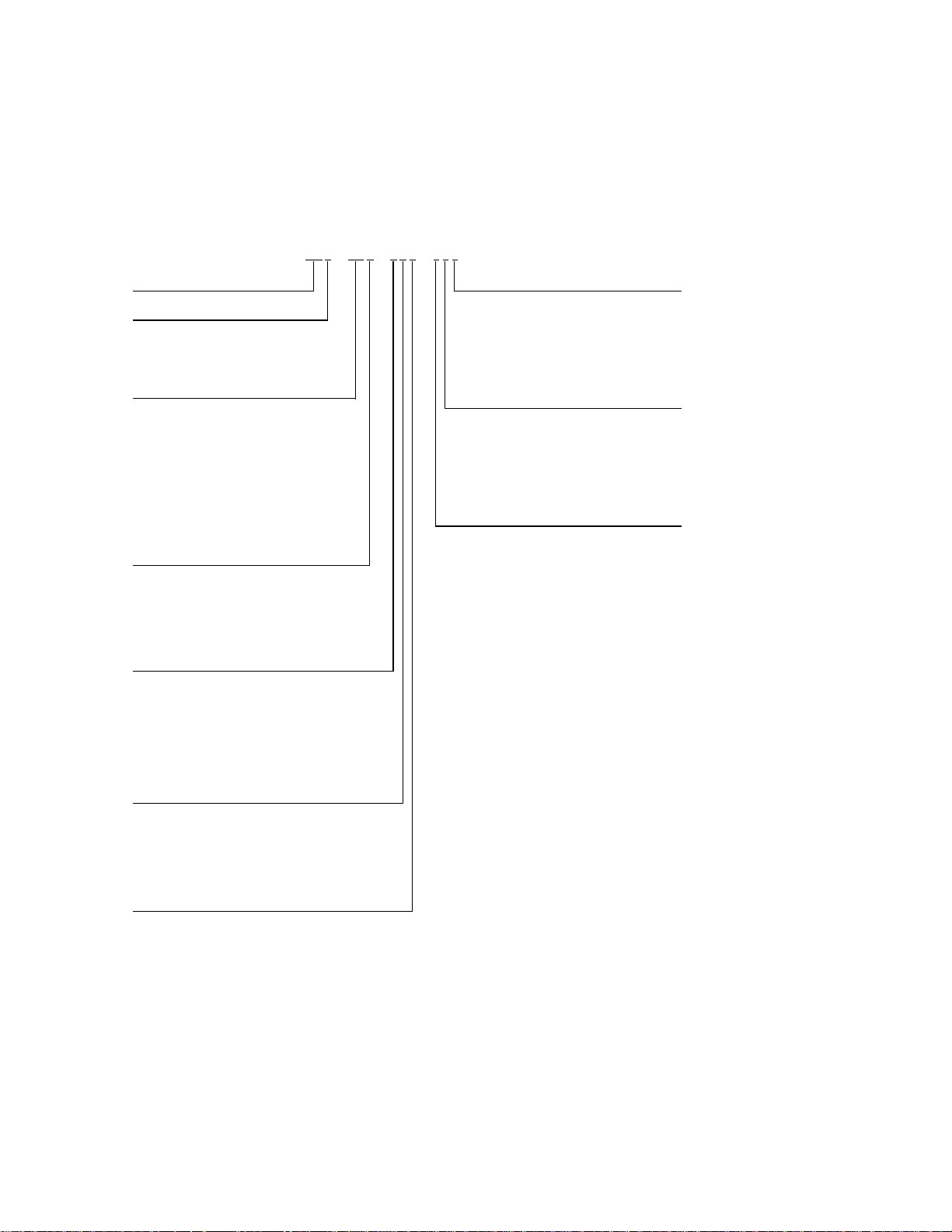
The following Ordering Code defines the new
g
g
g
g
g
g
g
g
g
g
Q
g
g
g
g
A
g
g
A
g
g
g
g
g
g
g
g
g
Q
Q
g
g
g
g
g
g
g
g
g, g
g
g
GV Series pump and pump/motor and top plate
arrangements. When quoting or ordering a GV
Ordering Code enables Carver Pump Company
to accept orders quickly, assuring timely and
correct manufacture of the desired pump.
pump, this Ordering Code must be used. This
EXAMPLE
---
Pump Series Coupling, Motor Mounting Bracket and Motor
GV - General Vertical A - Standard couplin
Mountin
Style C - Standard coupling, TEFC motor, standard efficiency
C - Cantilever desi
T - Top pull out desi
S - Sump desi
Casin
Nozzle and Impeller S i ze s
BA - 1 1/4 x 1 x 7 DA - 2 x 1 x 11 Motor Ratin
BB - 1 1/2 x 1 1/4 x 7 DB - 4 x 2 x 11 A - 1.5 HP @ 1750 RPM K - 15 HP @ 1750 RPM V - 75 HP @ 1750 RPM
BC - 2 1/2 x 2 x 7 DC - 4 x 3 x 11 B - 2 . 0 H P @ 17 50 R P M M - 15 HP @ 3500 RPM W - 100 HP @ 1750 RPM
BD - 3 x 2 1/2 x 7 DD - 5 x 4 x 11 C - 3.0 HP @ 1750 RPM N - 20 HP @ 1750 RPM
BE - 4 x 3 x 7 DE - 8 x 6 x 11 D - 5.0 HP @ 1750 RPM P - 20 HP @ 3500 RPM X - S p e ci al or over 100 HP
BF - 5 x 4 x 7 E - 5.0 H P @ 35 00 R P M
CA - 1 1/2 x 1 1/4 x 10 EB - 2 1/2 x 2 x 13 G - 7.5 HP @ 35 00 R P M S - 40 HP @ 1750 RPM
CB - 2 x 1 1/2 x 10 EC - 3 x 2 1/2 x 13 H - 10 HP @ 1750 RPM T - 50 HP @ 1750 RPM
CC - 2 1/2 x 2 x 10 ED - 4 x 3 x 13 J - 10 HP @ 3500 RPM U - 60 HP @ 1750 RPM
CD - 3 x 2 1/2 x 10 EE - 5 x 4 x 13
CE - 4 x 3 x 10 EF - 6 x 5 x 13
CF - 5 x 4 x 10 EG - 8 x 6 x 13 (GVC & T only) Top Plate and Dischar
CG - 6 x 5 x 10 A - Small steel top plate (no dischar
Basic Mate rials and Construction
ll cast iron construction
A -
316 stainless steel fitted cast iron construction
B -
ll 316 stainless steel construction for major components
C -
- Special
X
Column Depth (1.0 and 2.0 ft for GVC & T only) L - L
A - 1.0 ft (GVC & T) L - 11.0 ft (GVS only) M - L
B - 2.0 ft (GVC & T) M - 12.0 ft (GVS only)
C - 4.0 ft (GVS only) P - 14.0 ft (GVS only) P - L
D - 5.0 ft (GVS only)
E - 6.0 ft (GVS only) R - 16.0 ft (GVS only)
F - 7.0 ft (GVS only) S - 17.0 ft (GVS only) R - Lar
G - 8.0 ft (GVS only) T - 18.0 ft (GVS only) S - Lar
J - 9.0 ft (GVS only) U - 19.0 ft (GVS only) T - Lar
K - 10.0 ft (GVS only) V - 20.0 ft (GVS only)
Throttle Bushin
A - Teflon bushin
B - 17-4 PH bushin
C - Bronze lineshaft bearin
D - Bronze lineshaft bearin
E - Carbon lineshaft bearin
X - Special
n D - S tandard coupling, TEFC motor, Hostile Duty
n E - Standard coupling, X-P motor, standard efficiency
n
EA - 2 1/2 x 1 1/2 x 13 F - 7.5 HP @ 17 50 R P M R - 30 HP @ 1750 RPM Z - No motor - bare pump
N - 13.0 ft (GVS only) N - L
- 15.0 ft (GVS only)
, Lineshaft Bearing and Flush Lines W - Large 316 SS top plate, double oversized 316 SS discharge (GVC & T only)
(standard for GVC & T)
, 416 SS shaft sleeve (GVC & T only) X - Special
reased for life (standard for GVS) Z - No top plate or discharge pipe - bare pump only (standard for GVC & T)
, externally flushed (GVS only)
, externally flushed (GVS only)
Z Z ZB A ZG V B E AC
B - Standard couplin
X - Special couplin
Z - No couplin
B - Small steel top plate (no dischar
C - Small 316 SS top plate (no dischar
D - L
. steel plate, no underliner, standard steel discharge pipe (standard for GVS)
E - L
. steel plate, no underliner, oversized steel discharge pipe (GVC & T only)
F - L
. steel plate, no underliner, dbl. oversized steel discharge pipe (GVC & T only)
. steel plate, 316 SS underliner, standard size steel discharge pipe
G - L
H - L
. steel plate, 316 SS underliner, oversized steel discharge GVC & T only)
J - L
. steel plate, 316 SS underliner, dbl. oversized steel discharge (GVC & T only)
. steel plate, no underliner, standard size 316 SS discharge pipe
K - L
. steel plate, no underliner, oversized 316 SS discharge (GVC & T only)
. steel plate, no underliner, dbl. oversized 316 SS discharge (GVC & T only)
. steel plate, 316 SS underliner, standard size 316 SS discharge pipe
. steel plate, 316 SS underliner, oversized 316 SS discharge (GVC & T only)
- Lg. steel plate, 316 SS underliner, dbl. o'sized 316 SS discharge (GVC & T only)
e 316 SS top plate, standard size steel discharge pipe
e 316 SS top plate, oversized steel discharge (GVC & T only)
e 316 SS top plate, double oversized steel discharge (GVC & T only)
U - Lar
e 316 SS top plate, standard size 316 SS discharge pipe
V - Lar
e 316 SS top plate, oversized 316 SS discharge (GVC and GVT only)
, ODP motor, standard efficiency
, ODP motor, Hostile Duty
, motor enclosure or motor speed
or motor - bare pump only
(when require d)
- 25 HP @ 1750 RPM
e Pipe Arrangement
e pipe), no underliner (GVC & T only)
e pipe), 316 SS underliner (GVC & T only)
e pipe), no underliner
Inlet Pipe and Strainer
A - Zinc plated steel strainer with steel tailpipe
B - 304 SS strainer with 316 SS tailpipe
X - Special strainer and/or tailpipe
Z - No strainer or tailpipe (standard)
* Casing Nozzle and Impeller Sizes containing codes BA through BF and CA through CG have semi-open impellers. Casing Nozzle
and Impeller Sizes containing codes DA through DE and EA through EG have closed impellers.
Figure A. Ordering Codes
3

III. INSTALLATION.
V. OPERATION.
Skilled personnel should install the pump in
accordance with engineering standards. Faulty
installation will result in operating troubles and
premature wear of parts.
The pump and driver should be easily accessed with
enough headroom to perform periodic inspection and
maintenance. The pump should always be
submerged enough to prevent vortexes from forming,
which might allow air to enter the suction.
When pump is supplied with coupling, motor, and
baseplate, the complete set is assembled at Carver
Pump Company. After ascertaining that the unit has
suffered no damage in transit, one may install the
pumping unit. Proceed as follows:
1. Make sure the mounting surface is level.
Attach the base to the mounting surface.
Check that pump rotates freely.
CAUTION
Pipe strain will cause wear and/or damage to
parts.
2. Connect discharge piping. Extreme care
should be taken when connecting new piping
lines to be sure that no foreign matter such
as dirt, chips, tools, etc., is in the piping,
tank, or return piping as the debris will be
drawn into the pump and cause excessive
damage. Any debris caught in the pump
passageways will throw the pumping unit out
of balance.
3. Connect any necessary auxiliary piping and
gauge lines.
4. Since the pumping unit is shipped with
bearings packed, initial greasing will not be
necessary unless pumping unit has been in
storage for an extended period of time (refer
to section II).
5. Turn pump and motor shafts by hand to be
sure they rotate freely.
6. Connect wiring to motor. Due to high voltage
required to operate the pumping unit,
personnel working with the equipment
should be familiar with electrical safety
practices and modern methods of
resuscitation.
7. Connect electrical power supply to motor.
8. Open system valves.
IV. ALIGNMENT.
A flexible coupling connects the pump and motor.
The motor bracket aligns the pump and motor. No
further alignment is necessary.
A. PRESTART CAUTIONS.
1. Before starting or operating the pump, read
this entire manual, especially the following
instructions.
2. Before starting the pump, rotate shaft by
hand to assure all moving parts are free.
3. Before starting the pump, install closed
guards around all exposed rotating parts.
4. Observe all caution or danger tags attached
to the equipment.
5. Never run pump dry. Dry running may result
in pump seizure.
6. If excessive vibration or noise occurs during
operation, shut the pump down and consult a
Carver representative.
7. Use of a check valve in discharge piping is
recommended if there is a high volume of
reverse flow.
8. Check level in tank to see that the pump is
submerged in fluid.
B. STARTING THE PUMP. The pumping unit will
operate without operator intervention once system
valves have been adjusted to the specified pumping
conditions. The casing of the pump will be submerged
in the fluid being pumped, thus rendering it selfpriming. Proceed with operation as follows:
1. Make sure no one is working on the pumping
unit.
2. If the pumping unit has been idle for a period
of time, make sure unit is firmly attached to
its foundation.
3. Open valves to pressure gauges in system.
CAUTION
Check level of liquid in tank to be sure
casing is under liquid level.
4. Jog starter switch on motor to check
direction of rotation. Direction of rotation is
clockwise from fan end of motor.
5. Partially open discharge valve.
6. Start the pumping unit in accordance with
the directions on the electrical power supply.
7. Slowly adjust discharge valve to operating
condition required.
8. Pumping unit is now in full operation.
C. STOPPING THE PUMP. To stop the pump,
use the following process:
1. If pump is being stopped for overhaul, slowly
close the discharge valve. Otherwise leave
discharge valve set at condition.
2. Stop the pumping unit in accordance with the
directions on the electrical power supply.
3. If the pump is being stopped for overhaul,
close pressure gauge valves.
4

4. The pumping unit is now in the off position.
VI. MAINTENANCE.
Generally, the pump does not require continuous
supervision. Occasional visual checks are
recommended. Data should be recorded for each
pump to keep track of maintenance, which has been
performed and note operational problems. A pump
service record page is provided for this purpose in the
front matter of this manual.
Before disassembly/assembly, review Table A,
Torque Values to avoid equipment damage and injury
to personnel.
Table A. Recommended Torque Values (ft-lbs)
Bolt
Size
Composite
¼”-20 5 5 7
5/16”-18 11 11 12
3/8”-16 18 18 21
½”-13 33 39 45
5/8”-11 54 83 97
¾”-10 80 105 132
7/8”-9 109 160 203
1”-8 144 236 300
A. FIELD INSPECTION. Shutdown is not
required. Perform field inspection at regular intervals
and cover the following procedures:
1. Check and record the suction and discharge
pressures to establish differential head. It
should conform to the pump nameplate.
2. Check and record the power input and speed
of the driver.
3. Check and record pumping temperatures.
4. Check pump for quiet running.
B. STUFFING BOX. The stuffing box is equipped
with a throttle bushing which requires no regular
maintenance. The inside diameter of the throttle
bushing will increase with wear. The throttle bushing
should be inspected after pump disassembly. The
throttle bushing requires replacement if the inside
diameter is more than 0.020 inch out of round.
C. BEARING TEMPERATURE. Bearing
temperature should be monitored periodically. Normal
operating temperatures are 120 degrees F to 160
degrees F, depending on the ambient temperature.
Bearings may appear to run hot when pump is first
started. This is caused by the shaft seal, not the
bearing. When the seal is seated, temperature should
drop to normal.
Material
Steel (or
otherwise
noted)
316
Stainless
Steel
Check bearing temperature by placing a pyrometer
against the bearing frame while pump is running. A
temperature rise above 180 degrees F indicates
possible damage that requires checking. The most
common cause of high bearing temperatures is
overgreased bearings.
D. BEARING LUBRICATION. Lubrication
frequency depends on operating conditions. Normal
duty calls for relubrication every 1000 hours of
operation. Bearings are lubricated at Carver Pump
Company with Amoco Rykon Premium Grease No.
2EP, non-soap, polyurea thickened grease with a
drop point of 450 degrees F. This grease was
selected due to its suitability to extreme pressures
and its high temperature stability. Never mix greases
with differing properties.
Polyurea base greases are NOT compatible with
lithium or soda soap base greases. Therefore, the
type of grease added should not vary. However, if it is
necessary to change grease types, the bearings,
bearing frame, and bearing cap/cartridge should be
thoroughly cleaned and flushed with suitable solvent
to remove all traces of old grease. Disassemble
pump, remove shaft and bearings from bearing frame,
and follow these procedures:
1. Place bearings, bearing frame, and
bearing cap/cartridge in a wire or mesh
basket and suspend the basket in a light
mineral solvent. Allow it to soak,
preferably overnight.
2. After soaking and cleaning, the bearings,
bearing frame, and bearing cap/cartridge
should be rinsed in a clean, light mineral
solvent and agitated vigorously to remove all
loosened hard grease and dirt.
3. Dip bearings in clean, light oil and spin by
hand to determine that all foreign matter has
been removed.
4. After cleaning, repack bearings half full on
both sides with a good quality ball bearing
grease.
To relubricate bearings use the following procedure:
CAUTION
Overgreasing creates heat and is the cause
of many problems requiring repair. DO NOT
OVERGREASE.
1. Never relubricate pump bearings while unit is
running. If necessary, shut down pump
according to section V, paragraph C.
2. Remove plugs opposite grease fittings on
both ends of bearing frame.
5
 Loading...