

Carver 2157 MONTEGO, 2557 MONTEGO, 2357 MONTEGO, 2767 SANTEGO, 2587 ALLEGRA Owner's Manual
...
r-
i.
'
~~"~".~
SEPTEMBER 1988
MODELS
2157 MONTEGO
2357 MONTEGO
2557 MONTEGO
2587 ALLEGRA
2757 MONTEGO
, 2767 SANTEGO
OWNER'S
M'ANUAL·
.,---
:,.......--....
..
OMSB
~~~~~~"
CARVER----,
~
"
~rver
Boat, Corporation
.,fSula'ski,
WI
54162-1010
TABLE OF CONTENTS
SECTION DESCRIPTION
PAGE
SECTION
A·
WARRANTY & SERVICE INFORMATION
A-1
CARVER WARRANTY POLICY ....................................................................................
A1
A-2 PRE-DELIVERY SERVICE ........................ , ...................................................................
A1
A-3
WARRANTY INFORMATION ........................................................................................
A1
A-4 SECOND OWNER REGISTRATION ..............................................................................
A1
SECTION B • ENGINES & DRIVE SYSTEMS
B-1
GENERAL .................. , ...................................................................................................
B1
B-2 ENGINE EXHAUST .............~ ..........................................................................................
81
B-3
STERN DRIVE SYSTEMS ............................................................................................
B2
B-4 ENGINE COOLING SYSTEMS ......................................................................................
B2
B-5 PROPELLERS
..
.............. .............. ........ ............................... ............ ......... ............. .......
B3
B-5A
Diameter .................................................................................................................. 83
B-5B Pitch ........................................................................................................................
B3
B-SC
Prop Slip .................................................................................................................. 83
B-6 ENGINE INSTRUMENTATION ...................................................................................... 83
B-6A
Tachometer..............................................................................................................
B4
B-6B
Temperature Gauge ..................... , ..........................................................................
B4
B-6C
Oil Pressure Gauge .................................................................................................. 84
B-6D
Voltmeter.. ........ ..... ........ ...... ................ ........................................ ...................... .......
B4
8-6E
Fuel Gauge ............................................................................................................... 84
8-6F
Power Trim Gauge .................................................................................................. 84
B-6G
Engine Alarm Systems ........................................................................... .................
84
8-6H
Engine Synchronizer ................................................................................................ 84
B-61
Instrument Maintenance ..........................................................................................
B4
SECTION C • CONTROL SYSTEMS
C-1
GENERAL
..
: ...................................................................................................................
C1
C-2 CONTROL OPERATION ................................................................................................
'C1
C-3 NEUTRAL SAFETY SWITCH ......................................................................... :
..
: ...........
C1
C-4 DUAL STATION CONTROLS ........................................................................................
C1
C-5 CONTROL SYSTEM MAINTENANCE ............................................................................
C1
SECTION 0 • STEERING SYSTEMS
D-1
GENERAL ......................................................................................................................
D1
D-1
A Mechanical Steering .... ............................................................................................
D1
D-18 Hydraulic Steering............................. ............ ...........................................................
D1
D-2 OUTDRIVE POSITION INDICATOR .............................. : ...............................................
D1
D-3
PROPELLER TORQUE ............................................................... , ..................................
D1
D-4 POWER STEERIt'ltG .............................. ............. ............. ............ ...................
...
............
D1
D-5
POWER STEERING MAINTENANCE ............................................................................
D2
SECTION E • ELECTRICAL SYSTEMS
E-1
GENERAL ......................................................................................................................
E1
E-2 BATTERY SYSTEMS ....................................................................................................
E1
E-2A Single Battery Systems ............. .......... ............. .............. ............... ...........................
E1
OMSB
CARVER
E-2A1 Installation ..........................................................................................................
E1
E-2A2
Operation ..........................................................................................................
E1
E-2B Dual Battery Systems ................. ...................... ...... .................... .............................
E1
E-2B1
Installation ..........................................................................................................
E1
E-2B2
Operation ...... ............................. ..... ........... ....................................................... E2
E-3
BATTERY SYSTEM MAINTENANCE ............................................................................ E2
E-4 VOLTMETER USE
& OPERATION ................................................................................ E2
E-5
12
VOLT
ELECTRICAL EQUIPMENT ............................................................................ E3
E-5A Helm Equipment .......................................... ............................................................
E3
E-5B Interior Equipment .................................................................................................... E4
E-5C Head Electrical Equipment.............. ................................ .......................................... E4
E-5D Installation of Additional 12 Volt Equipment .............................................................. E4
120
VOLT
ELECTRICALSYSTEM ...................... ............................................................ E4
E-7 DOCKSIDE ELECTRICAL
SYSTEM
.............................................................................. E4
E-8
120
VOLT
DOCKSIDE OPERATION ............................................................................. .
E-8A
General .................................................................................................................... E5
E-8B
Shore Power Connections .................................. ........... ........................................... E5
E-8C Polarity Indicator ........................................... ............... ............................................ E6
E-9
ELECTRICAL SYSTEM MAINTENANCE ........................................................................ E6
E-10
ELECTROLYSIS
& CORROSION .................................................................................. E6
OA
Electrolysis .............................................................................................................. E6
E-10B
Galvanic Corrosion .......... .......................................................................................
.E6
SECTION
F·
FUEL SYSTEMS
F-1
GASOLINE FUEL
SYSTEMS
........................................................................................
F1
F-1
A System Testing ........................................................................................................
F1
F-1
B Fuel Fills ............. ........ ................... ............................. ........................... ....... .... .......
F1
F-1C Fuel Vents .......................................................................................... : ......................
F1
F-i
D Anti-Syphon Valves ..................................................................................................
F1
F-1
E Fuel Gauge ..............................................................................................................
F1
F-i
F Fuel Filters ..............................................................................................................
Fi
F-i
G Use and Maintenance ..............................................................................................
F1
F-i
H Fume Detector .......................................................................................................... F2
F-2 FUELING INSTRUCTIONS ............................................................................................ F2
SECTION G • WATER SYSTEMS
G-1
GENERAL ......................................................................................................................
G1
. G-2 PRESSURIZED WATER SYSTEM ................................................................................
G1
G-2A
Water
Supply Tanks ................................................................................................
Gi
G-2B Priming the System ..................................................................................................
G1
G-2C System Operation ....................................................................................................
Gi
G-2D Water Heating Systems ......................................................... ; ................................... G2
G-2E
Shower .................................................................................................................... G2
G-3
WATER SYSTEM MAINTENANCE ................................................................................
G2
G-4
COCKPIT
WASHDOWN ...................................................... : .........................................
G2
SECTION
H·
VENTILATION & DRAINAGE
H-1
ENGINE
COMPARTMENT
VENTILATION ....................................................................
Hi
H-1A Gravity Ventilation System
..~ .....................................................................................
Hi
H-iB
Forced Air Ventilation ............................................................................................
:.
Hi
H-1C Engine Compartment Ventilation Maintenance ..........................................................
Hi
H-2
CABIN VENTILATION ....................................................................................................
Hi
H-3
HULL DRAINAGE SYSTEMS ........................................................................................
Hi
OMSB
CARVER
2
H-3A Garboard Drain ........................................................................................................
H1
H-3B
Bilge Pumps ............................. , ............................................................................... H2
H-3C
Bilge Compartment Drainage.................................................................................... H2
SECTION I • INTERIOR EQUIPMENT
i-1
HEADS
1-1
A Self-Contained Head.......... ............... .......................................................................
11
1-1
B Manually-Operated Head ..........................................................................................
11
1-1
C Electric Head ............................................................... ;........... ............ ............. ........
11
1-1
D Crown Electric Head ................................................................................................
11
1-1
E Auxiliary Holding Tank ..............................................................................................
11
1-2
REFRIGERATORS ........................................................................................................
12
1-3
STOVES ..................... .................... ................................................................ ........... ....
12
1-3A
Alcohol Stoves ....................... ........................................................................... ......
12
1-3B
Alcohol/Electric Stoves ........................... : ................................................................
12
1-4
STEREO EQUIPMENT ..................................................................................................
12
1-5
AIR CONDITIONING ......................................................................................................
12
SECTION J • EXTERIOR &
~AFETY
EQUIPMENT
J-1
SPOTLIGHT ..................................................................................................................
J1
J-S
TRIM TABS ....................................................................................................................
J1
J-SA
Operation .................................................................................................................
J1
J-SB
Correct Usage ............................................................................ : .............................
J2
J-B
RAILS & DECK HARDWARE ........................................................................................ J2
J-2
COMPASS ....................................................................................................................
J1
J-3
ENGINE HOUR METER .................................................................................................
J1
J-4 DEPTH SOUNDERS ......................................................................................................
J1
J·4A 21,
23 & 2S
Foot Models ...........................................................................................
J1
J·4B
27 Foot Models ........................................................................................................
J1
J-7
SWIM PLATFORMS ...................................................................................................... J3
J-8
BOW PULPITS .............................................................................................................. J3
J-9
FIRE EXTINGUISHER SYSTEM .................................................................................... J3
SECTION K • SEATING
&WEATHER COVERS
K-1
V-BERTH FILLER CUSHIONS ......................................................................................
K1
K-S
DRAPERIES & WINDOW COVERS ......................... ............. .................... ............. ....... K2
K-B
CARVER WEATHER COVERS ............... ........................... ......... .......................... .........
K2
K·2
DINETIE
BERTHS .......................................................................................................
,:
K1
K-3 CONVERTIBLE STERN SEATS ....................................................................................
K1
K-4 UPHOLSTERY MAINTENANCE ..................... .............. ............. ...................... ........... ....
K1
K-4A Exterior Upholstery ..................................................................................................
K1
K-4B Interior Upholstery .............. ................ ................... .................. ........ .........................
K1
K-4C Upholstery Replacement ...........................................................................................
K1
K-4D Exterior Carpets ......................................... ; ............................................................
K1
K-4E Interior Carpets ........................................................................................................
K1
K-7 WINTER STORAGE COVERS ..................................... ' ....................................... , .........
K3
SECTION L • FIBERGLASS
HULL
&COMPONENTS
L-1
GENERAL ...................................................................................................................... L1
L-S
HULL SUPPORT ..................................................... : ......................................................
L2
L-B
FIBERGLASS REPAIRS ........ : ....................................................................................... L2
L-2 FIBERGLASS COMPONENT CONSTRUCTION ... : ........................................................ L
1
L-3 ADDITIONAL EQUIPMENT INSTALLATION
..
; ............. ~ ................................................. L1
L-4 FIBERGLASS CARE .........................
~........
....................... ............... .......... .................... L1
OMSB
CARVER
3
"------------
-~~---.,,-~-
.~.----~-..~--""-.-",,"-----.,,--
---
SECTION M • WOODWORK CARE &MAINTENANCE
M-1
TEAK
CARE
& MAINTENANCE ....................................................................................
M1
M-2
DECRAGARD
CARE
& MAINTENANCE ........................................................................
M1
M-3
HIGH-PRESSURE LAMINATE CARE ............................................................................
M1
M-4
PLEXIGLASS
CARE
......................................................................................................
M1
M-5
DASH
PANELS
...
: ..........................................................................................................
M1
SECTION N • GENERAL MAINTENANCE
N-1
PRIOR
TO
LIFTING
FOR
WINTER LAY-UP ..................................................................
N1
N-2 AFTER LIFTING ............................................................................................................
N1
N-3
PRIOR
TO
WINTER STORAGE ....................................................................................
N1
SECTION
O·
OPERATION
0-1 GENERAL ...................................................................................................................... 01
0-2
COMPONENT SYSTEMS .............................................................................................. 01
0-3
SAFETY EQUIPMENT .................................................................................................. 01
0-4
RULES
OF
THE
ROAD
.................................................................................................. 01
0-5
PRE-CRUISE SYSTEM
CHECK
.................................................................................... 01
0-5A Before Starting the Engine ....................................................................................... :
01
0-5B After Starting the Engine ......... .............................. ............ ....................................... 01
0-6
GROUNDING & TOWING ..............................................................................................
02
0-7
GLOSSARy................. ......... ........................... ....................................... ........................
02
OMSB
CARVER
4
I
f'.
(
(
'-
/ '
J
.
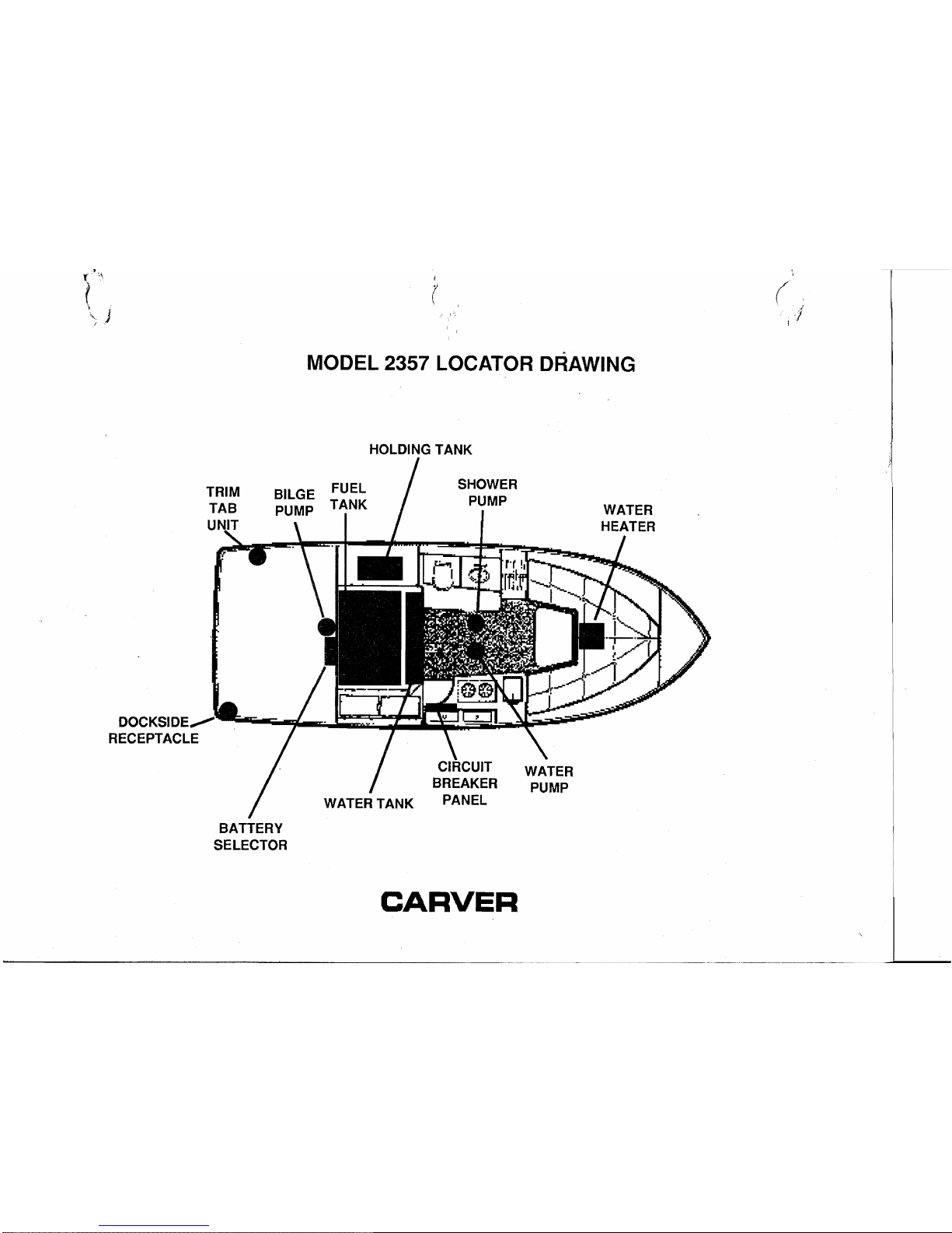
MODEL 2357 LOCATOR DRAWING
HOLDING
TANK
DOCKSI
RECEPTACLE
FUEL
TANK
SHOWER
PUMP
CIRCUIT
BREAKER
PANEL
BATTERY
SELECTOR
CARVER
ENGINES
& DRIVE
SYSTEMS
B-1
GENERAL
Carver Boat Corporation does not manufacture engines, stern drives or v-drives. These components are
built by manufacturers that are specialists in this field.
Because
of
the technica I nature of the engine and drive
systems, all manufacturers
of
these items require that
warranty and service problems be taken directly to
them for resolution. The Service Department of Carver
Boat Corporation stands ready to assist boat owners
when communicating with the manufacturers of engines and drive systems. Prior to contacting the Carver
Service Department, thoroughly review any problem
with your Carver dealer.
In
compliance with the Federal Safe Boating Act
of
1971, all engine manufacturers require their products to
be registered. A registration card
is
furnished with each
new engine. When selling a Carver boat, the dealer,
along with the purchaser, should complete the information requested on these cards and return them to the
respective engine manufacturer. (Engine registration
cards can be found in this manual).
Most manufacturers
of
the various marine power
components used
in
these boats provides an owners
manual with the product. These publications are included with this manual. Read the manual(s) carefully
and become completely familiar with the proper care
and operation of the engine and drive system.
B-2
ENGINE EXHAUST
Do Not inhale exhaust fumes! Exhaust contains carbon
monoxide which is colorless and odorless. Carbon
monoxi(:le
is
a dangerous gas that is potentially lethal.
The
following
suggestions
can
help
prevent
ex-
haust
fumes
from
entering
your
boat:
1.
Do Not allow the boat to remain stationary with the
engines operating for an extended period of time.
2.
Use extreme caution while operating the engines
in
confined areas such as enclosed slips, congested
piers, or
in
any area where the exhau!)t outlets are
facing
or
near a bulkhead or wall structure
of
any kind.
Operation under such conditions could easily lead to
exhaust gasses (carbon monoxide) entering the boat.
even though you may have all the hatches, windows,
doors and portholes closed.
3.
Neveroperatethegeneratorwhiletheboat
is
moored
against any other boat, dock
or
wall structure that
is
against
or
near,the exhaust outlet. Again, operation
under such conditions could easily lead to exhaust
gasses (carbon monoxide) entering the boat orthe boat
to which you are moored, even though you may have all
the hatches, windows, doors, and portholes closed,
4.
Persons sleeping can be easily overcome by carbon
monoxide because they are unaware of its presence.
Sleeping while the engines or generator are running
is
llQ1
recommended. If persons are sleeping aboard while
OMSB
81
CARVER
underway, or while the generator
is
running, those
awake should be extremely watchful for carbon monoxide accumulation in the cabin; especially the sleeping
areas. Open forward facing windows or deck hatches
to provide adequate fresh air ventilation. Keep hatches,
windows, and doorways that face aft or towards the
exhaust discharge closed.
5.
Ventilate your cabin while underway. Open a forward
hatch, porthole, or window to allow
airto
travel through
the cabin. Be very careful of operating the boat with the
cabin door
or
other windows, hatches, or portholes that
face aft, open. The natural vaccuum created during
operation may allow exhaust gasses to be drawn into
the cabin.
6.
Inspect the engines exhaust system frequently.
7.
Have a competent marine engine service technician
inspect the exhaust system whenever the boat
is
in for
service, or
if a change is noted in the sound
of
the
engines.
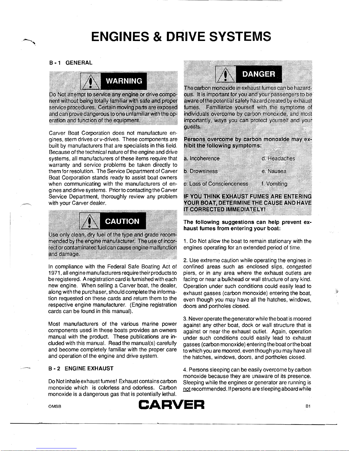
B-3
STERN DRIVE SYSTEMS
A stern drive or inboard/outboard propulsion system
has a piston engine equipped with special marine
components mounted near the transom and coupled to
an
external outdrive type transmission unit.
Thistype
of system
is
depicted in Figure
B1.
Consult the Engine Owners Manual that has been
provided with this manual for additional information
regarding operation and maintenance.
B - 4 ENGINE COOLING SYSTEMS
All marine engines use surface water as a cooling
medium. The cooling water employed enters the system through a water intake and
is
relinquished through
the exhaust manifolding system.
Most stern drive units have the water intake and ex-
haust system incorporated into the outdrive. See the
Engine Owners Manual for additional information.
Installation of "Fresh Water Cooling" provides adequate
engine cooling without exposing the internal engine
cooling system to the detrimental effects of surface
water. Fresh Water Cooling
is
recommended when the
boat will be operated in salt, highly polluted, or silt laden
water. Ask a Carver dealer for recommendations
regarding the necessity of fresh water cooling
in
the
boating area to be used. The Engine Owners Manual
provides additional information regarding service and
maintenance
of
this equipment.
FIGURE
B1
• TYPICAL STERN DRIVE
82
OMS8
CARVER
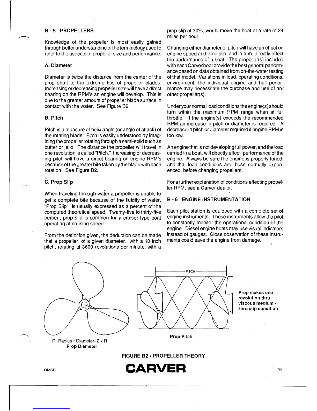
8 - 5 PROPELLERS
Knowledge of the propeller
is
most easily gained
through better understanding of the terminology used
to
refer to the aspects of propeller size and performance.
A.
Diameter
Diameter is twice the distance from the center of the
prop shaft
to
the
extreme tips
of
propeller blades.
I ncreasing or decreasing propelle r size will have a di rect
bearing on the RPM's an engine will develop. This is
due
to
the greater amount of propeller blade su rface in
contact with the water.
See
Figure 82.
8.
Pitch
Pitch is a measure of helix angle (or angle
of
attack) of
the rotating blade. Pitch is easily understood
by
imagining the propeller rotating through a semi-solid such as
butter or jello.
The
distance the propeller will travel in
one revolution is called "Pitch." Increasing
or
decreasing pitch will have a direct bearing on engine RPM's
because of the greater bite taken
by
the blade with each
rotation. See Figure
82.
C.
Prop Slip
When traveling through water a propeller is unable
to
get a complete bite because
of
the fluidity
of
water.
"Prop Slip" is usually expressed as a percent
of
the
computed theoretical speed. Twenty-five to thirty-five
percent prop slip is common for a cruiser type boat
operating at cruising speed.
From the definition given, the deduction can be made
that a
propeller,
of
a given diameter, with a 10 inch
pitch, rotating at 3600 revolutions per minute, with a
prop slip of 30%, would move the boat at a rate of 24
miles per hour.
Changing either diameter
or
pitch will have an effect on
engine speed and prop slip, and in turn, directly effect
the performance of a boat.
The
propeller(s) included
with each Carver boat provide the best general performance based on data obtained from on-the-water testing
of that model. Variations in load, operating conditions,
environment, the individual engine and hull performance may necessitate the purchase and use
of
an-
other propeller(s).
Under your normal load conditions the engine(s) should
turn within the maximum RPM range when at full
throttle.
If the engine(s) exceeds the recommended
RPM an increase in pitch or diameter is required. A
decrease in pitch or diameter required if engine RPM is
too
low.
An engine that is not developing full power, and the load
carried in a boat, will directly effect performance of the
engine. Always be sure
the
engine is properly tuned,
and that load conditions are those normally experienced, before changing propellers.
For a further explanation of conditions effecting propeller RPM, see a Carver dealer.
8 - 6 ENGINE INSTRUMENTATION
Each pilot station is equipped with a complete set of
engine instruments. These instruments allow the pilot
to constantly monitor
the
operational condition of the
engine. Diesel engine boats may use visual indicators
instead
of
gauges. Close observation of these instru-
ments could save the engine from damage.
Prop makes one
revolution thru
viscous
medium -
zero
slip
condition
..
~
R=Radius • Diameter=2 x R
Prop Diameter
Prop Pitch
FIGURE
82
• PROPELLER THEORY
OMSB
B3
CARVER
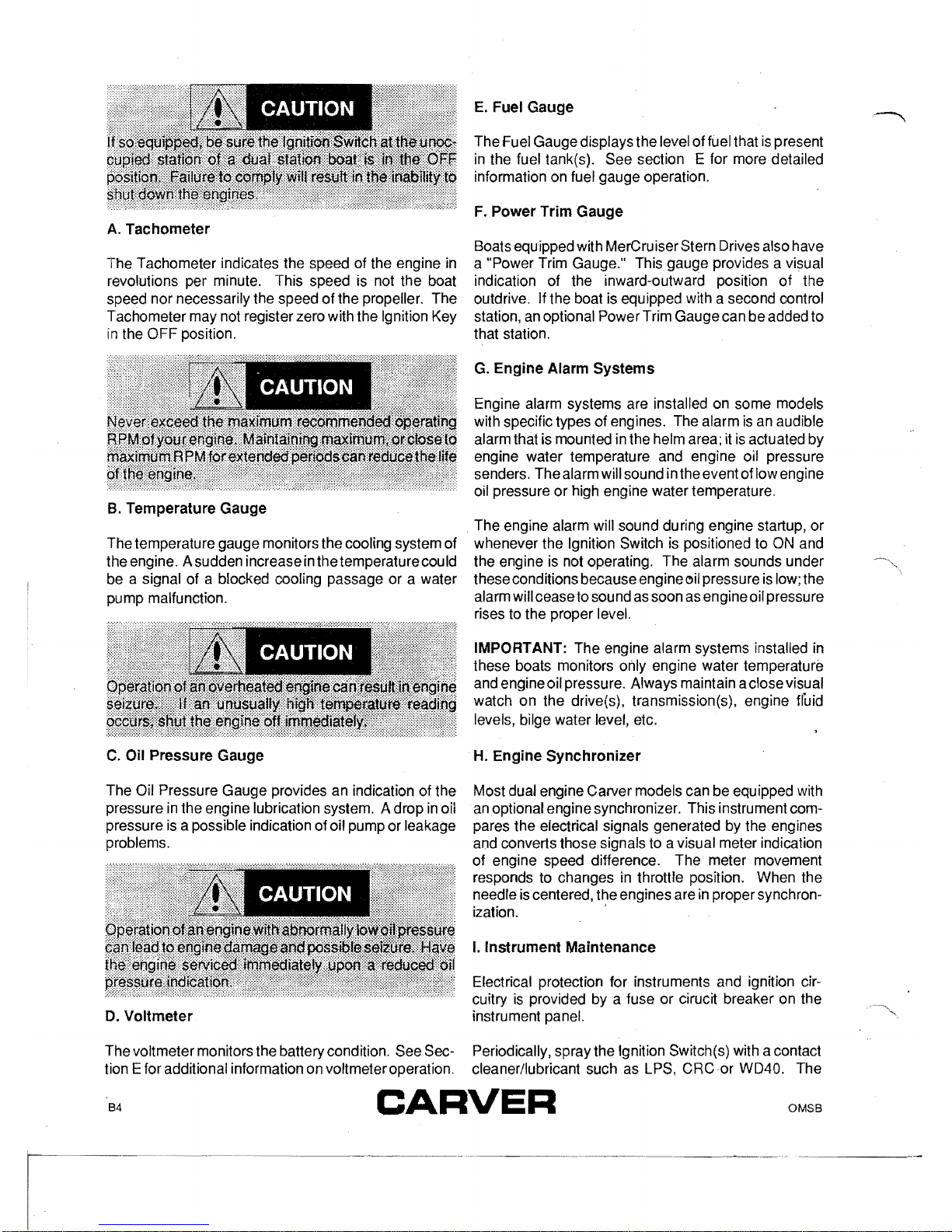
A.
Tachometer
The Tachometer indicates the speed of the engine
in
revolutions per minute. This speed is not the boat
speed nor necessarily the speed of the propeller. The
Tachometer may not register zero with the Ignition Key
in
the OFF position.
B.
Temperature
Gauge
The temperature gauge monitors the cooling system of
the engine. A sudden increase
in
the temperature cou
Id
be a signal of a blocked cooling passage or a water
pump malfunction.
C.
Oil
Pressure
Gauge
The Oil Pressure Gauge provides an indication of the
pressure
in
the engine lubrication system. A drop
in
oil
pressure
is
a possible indication of oil pump or leakage
problems.
D.
Voltmeter
The voltmeter monitors the battery condition. See Section E for additional information on voltmeter operation.
E.
Fuel
Gauge
The Fuel Gauge displays the level of fuel that
is
present
in
the fuel tank(s). See section E for more detailed
information on fuel gauge operation.
F.
Power
Trim
Gauge
Boats equipped with MerCruiser Stern Drives also have
a "Power Trim Gauge." This gauge provides a visual
indication of the inward-outward position
of
the
outdrive. If the boat is equipped with a second control
station, an optional Power Trim Gauge can
be
added to
that station.
G.
Engine
Alarm
Systems
Engine alarm systems are installed on some models
with specific types of engines. The alarm
is
an audible
alarm that is mounted in the helm area;
it
is
actuated by
engine water temperature and engine oil pressure
senders. The alarm will sound in the event of low engine
oil pressure or high engine water temperature.
. The engine alarm will sound during engine startup, or
whenever the Ignition Switch
is
positioned to
ON
and
the engine is not operating. The alarm sounds under
these conditions because engine oil pressure
is
low; the
alarm will cease to sound as soon as engine oil pressure
rises to the proper level.
IMPORTANT: The engine alarm systems installed
in
these boats monitors only engine water temperature
and engine oil pressure. Always maintain a close visual
watch
on
the drive(s), transmission(s), engine fluid
levels, bilge water level, etc.
H.
Engine
Synchronizer
Most dual engine Carver models can be equipped with
an optional engine synchronizer. This instrument compares the electrical signals generated by the. engines
and converts those signals to a visual meter indication
of engine speed difference. The meter movement
responds to changes in throttfe position. When the
needle
is
centered, the engines are
in
proper synchron-
ization. '
I.
Instrument
Maintenance
Electrical protection for instruments and ignition circuitry is provided by a fuse
or
cirucit breaker on the
instrument panel.
Periodically, spray the Ignition Switch(s) with a contact
cleaner/lubricant such as LPS,
CRCor
WD40. The
B4
OMSB
CARVER

Ignition Switch(s) and
aI/
instruments, controls,
etc.
should be protected from the weather when not
in
use.
Carver offers appropriate weather covers for each
model. Excessive exposure can lead to gauge and
Ignition Switch difficulties.
Electronic gauges are affected by static electricity that
builds-up on the glass face. Periodic washing of the
gauge face with warm water and mild liquid detergent
will help eliminate the static electricity problem and
improve gauge accuracy.
OMSB
85
CARVE'R
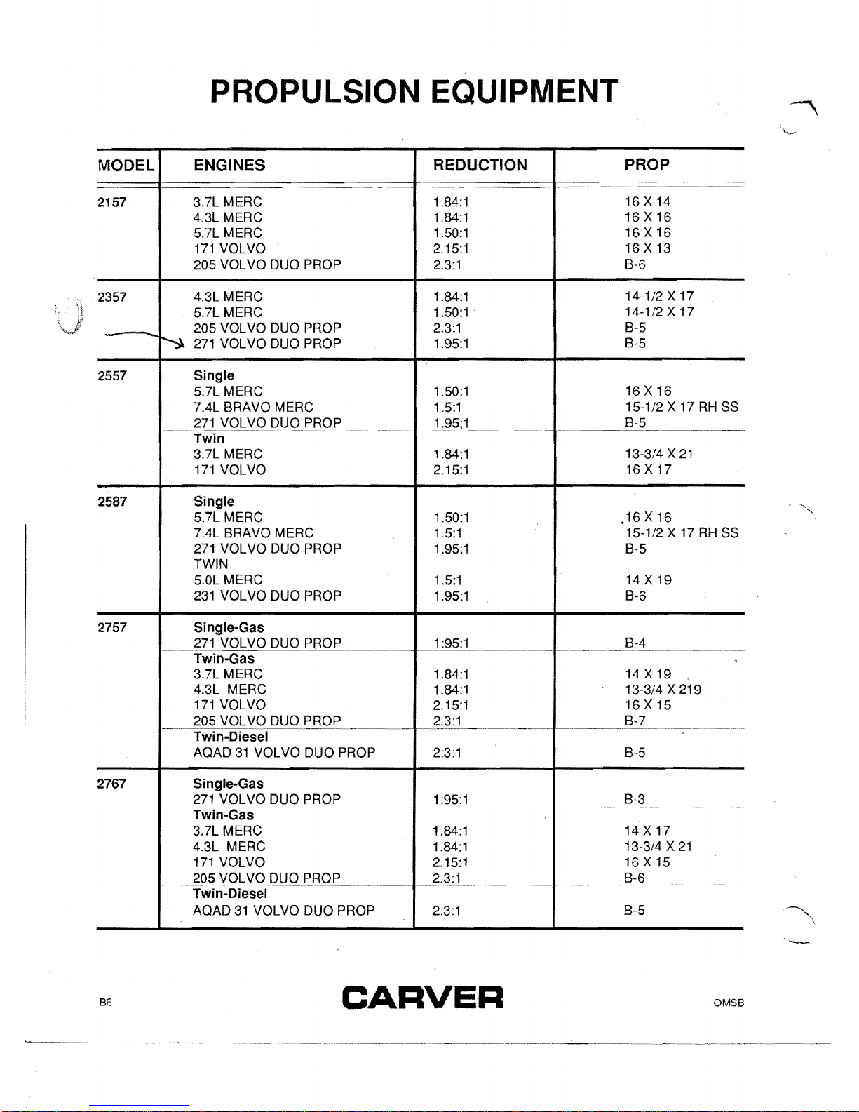
PROPULSION EQUIPMENT
PROP
ENGINES REDUCTION
MODEL
16 X 14
4.3L
MERe
2157 3.7L
MERe
1.84:1
16 X
16
5.7L
MERe
1.84:1
16 X 16
171
VOLVO
1.50:1
16 X 13
205 VOL
va
DUO PROP
2.15:1
8-6
2.3:1
14-1/2 X 17
5.7L
MERe
1.84:1
4.3L
MERe
2357
1.50:1 .
14-1/2 X 17
.
8-5
~
271
VOL
va
DUO PROP
2.3:1
205 VOL
va
DUO PROP
8-5
1.95:1
2557 Single
16 X 16
7.4L
8RAVO
MERe
5.7L
MERe
1.50:1
15-1/2 X 17
RH
SS
271
VOLVO
DUQPROP
1.5:1
8-5
1.95;1
.~-""~-------'-'~---'~--'---.
Twin
13-3/4 X
21
171
VOLVO
1.84:1
3.7L
MERe
16 X
17
2.15:1
Single
2587
5.7L
MERe
1.50:1
.16X16
7.4L
8RAVO
MERe
15-1/2 X 17
RH
SS
271
VOLVO DUO PROP
1.5:1
1.95:1
8-5
TWIN
5.0L
MERe
14 X 19
231
VOLVO DUO PROP
1.5:1
1.95:1
8-6
2757 Single-Gas
8-4
271
VOLVO DUO PROP
1
:95:1
r-'~~-
.......~......
~-
.~-~.
,
3.7L
MERe
Twin-Gas
1.84:1 14 X 19
4.3L
MERe
1.84:1 13-3/4 X 219
171
VOLVO
2.15:1 16 X 15
205 VOL
va
DUO PROP
8-7
2.3:1
---
..
---~.---
...
-----
...
--.~~-~~---~--~.
"--'~-----~---~~---'-
Twin-Diesel
AQAD
31
VOLVO DUO PROP 2:3:1
8-5
2767 Single-Gas
271
VOLVO DUO PROP 1
:95:1
8-3
.------.-------~-
...
------.--.-.
---
Twin-Gas---"--'--'
3.7L
MERe
14 X 17
4.3L
MERe
1.84:1
13-3/4 X
21
171
VOLVO
1.84:1
16 X 15
_~05
V_QLVODUP
PROE_.__.
2.15:1
8-6
2.3:1
Twin-Diesel
8-5
AQAD
31
VOLVO DUO PROP
2:3:1
B6
OMSB
CARVER
Tachometer
c:
III
...
purple
blue
bla
k
purple
ellow/red
:t
.0
..
-
V-drive
011
lender
1--~--4-~P
i
nk
$
-
..
-
red
V-drive
light
$
If.
0 e
qui
p p e d ............
..I..-L-"'-""--I..-L.
....
Engine
Harnel
•
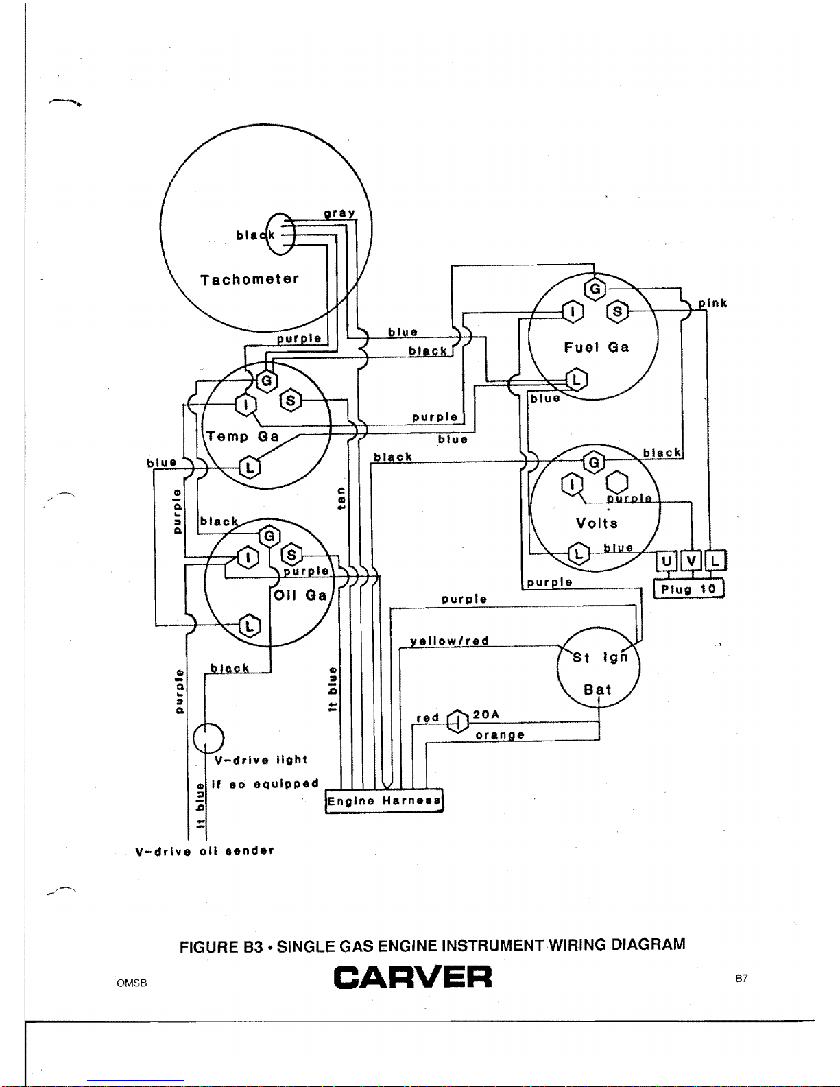
FIGURE
83
• SINGLE GAS ENGINE INSTRUMENT WIRING DIAGRAM
OMS8
CARVER
87
black
black
Tachometer
Tachometer
fIJ
Q.
...
Jtt.
fIJ
if
so
equipped
:)
Q.
Q.
..
U
...
:J
:::II
Q.
•
-
.Q
-
Q
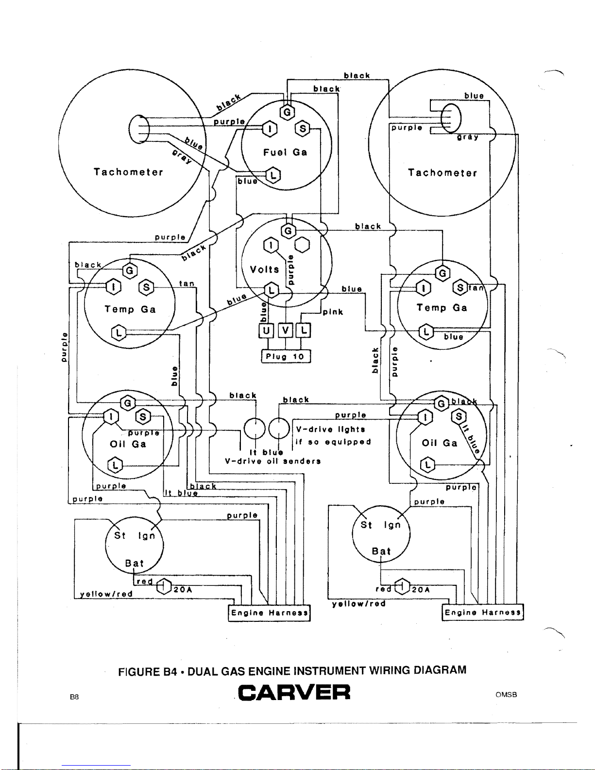
FIGURE
84
• DUAL GAS ENGINE INSTRUMENT WIRING DIAGRAM
OMSB
.
CARVER
88

\
)
)
)
o
:!:
(f)
:!!
OJ
Single
Engine
G)
Dual
Engine
c:
1
JJ
m
[D
01
•
en
z
G)
r-
m
Ro
I
Single
;statron
o
c:
l>
r-
~
<
o
r-
<
0
__
m
z
Abbt"~v.ated
Wirs
CQ(ot"s
~
~
I
I I
'.
---
_4_
.-J
n I
R'
I
--.---:~
~-~
'1
r1\
k
bl
~
=:f!0.:t!
II
~I",
li--1
.
.Ji.
f
I
kl
~
~
Alo".
0i
I
~
"
I:L~
kl-
fn-
.
15
@
;:~"
'@Ke
m
G)
lJ
m
z
z
en
-I
JJ
c:
s:
m
z
-I
§
JJ
Z
G)
o
:.;:
G)
JJ
l>
s:
b'lack-k
bhHJI-b
rcd-r
yeHo'fr-Y
g.f.on-n
whlhl-W
~fay-o
..
ortkng4t""O
o
'"
brown-bn
N"l~:
To
ola.I,
I
turn
kay
1eo
degrEt198
\-
____
t~
.&con~
'ON'
po.i.
~5
-.
I
~
tlon
~
Key
Stop
(I
II " Y
~~~
Stop
DUII11Stalion
I
~
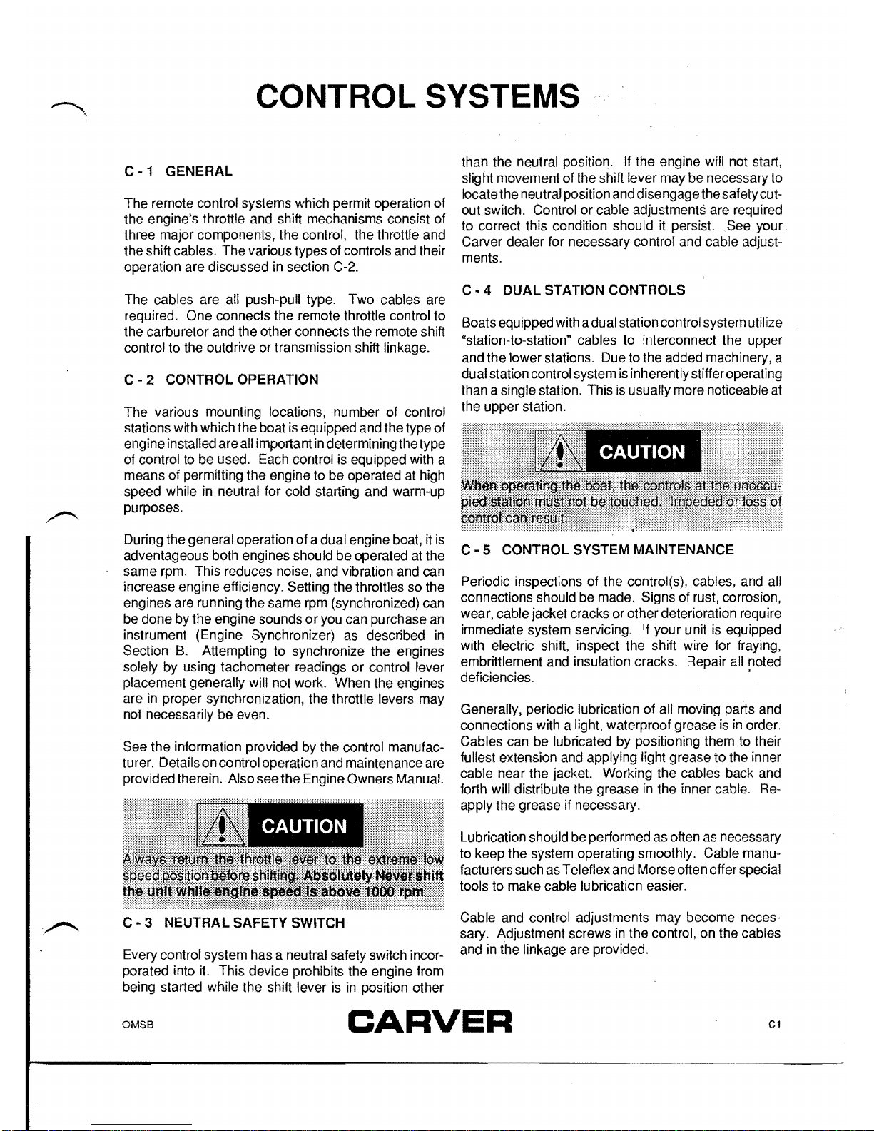
CONTROL SYSTEMS
C-1
GENERAL
The remote control systems which permit operation of
the engine's throttle and shift mechanisms consist of
three major components, the control, the throttle and
the shift cables. The various types of controls and their
operation are discussed in section C-2.
The cables are
all push-pull type. Two cables are
required. One connects the remote throttle control to
the carburetor and the other connects the remote shift
control to the outdrive or transmission shift linkage.
C - 2 CONTROL OPERATION
The various mounting locations, number of control
stations with which the boat is equipped and the type of
engine installed are all important
in
determining the type
of control to be used. Each control is equipped with a
means of permitting the engine to be operated at high
speed while in neutral for cold starting and warm-up
purposes .
.
/'--.
During the general operation of a dual engine boat,
it
is
adventageous both engines should be operated
at
the
same rpm. This reduces noise, and vibration and can
increase engine efficiency. Setting the throttles so the
engines are running the same rpm (synchronized) can
be done by the engine sounds
or
you can purchase
an
instrument (Engine Synchronizer) as described in
Section
B.
Attempting to synchronize the engines
solely by using tachometer readings or control lever
plac~ment
generally will not work. When the engines
are
In
proper synchronization, the throttle levers may
not necessarily be even.
See the information provided by the control manufac-
turer. Details on co ntrol operation and maintenance are
provided therein. Also see the Engine Owners Manual.
C - 3 NEUTRAL SAFETY SWITCH
Every control system has a neutral safety switch incor-
porated into it. This device prohibits the engine from
being started while the shift lever is in position other
than the neutral position.
If
the engine will not start
slight movement of the shift lever may be necessary
t~
locate the neutral position and disengage the safety cutout switch. Control or cable adjustments are required
to correct this condition should it persist.
.See
your
Carver dealer for necessary control and cable adjustments.
C - 4
DUAL
STATION CONTROLS
Boats equipped with a dual station control system utilize
"station-to-station" cables to interconnect the upper
and the lower stations. Due to the added machinery, a
dual station control system
is
inherently stiffer operating
than a single station. This
is
usually more noticeable
at
the upper station.
C - 5 CONTROL SYSTEM MAINTENANCE
Periodic inspections of the control(s), cables, and all
connections should be made. Signs of rust, corrosion,
wear, cable jacket cracks or other deterioration
requ
ire
immediate system servicing. If your unit
is
equipped
with electric shift, inspect the shift wire for fraying,
embrittlement and insulation cracks. Repair
all
noted
deficiencies.
>
Generally, periodic lubrication of all moving parts and
connections with a light, waterproof grease
is
in
order.
Cables can be lubricated by positioning them to their
fullest extension and applying light grease
to
the inner
cable near the jacket. Working the cables back and
forth will distribute the grease
in
the inner cable.
Re-
apply the grease if necessary.
Lubrication should be performed as often
as
necessary
to keep the system operating smoothly. Cable manufacturers such as Teleflex and Morse often offer special
tools to make cable lubrication easier.
Cable and control adjustments may become necessary. Adjustment screws
in
the control, on the cables
and in the linkage are provided.
OMSB
C1
CARVER
r-------------------~---
.........--.......--..

Other lubrication, adjustment and maintenance instructions are included
in
the information provided by the
control manufacturers.
C2
OMSB
CARVER
STEERING SYSTEMS
0-1
GENERAL
A.
Mechanical Steering
Most single station Carver boats use a rack and pinion
type mechanical steering system.
In
this system, a
pinion gear in the steering helm drives a gear rack
attached to the helm end of the steering cable. A rotary
rack is sometimes used. Though the appearance
is
different, the concept is the same. The steering cable
is
of
the push-pull type. As the wheel turns, the pinion
drives the rack which pushes or pulls the steering cable.
The steering cable on a stern drive model connects to
the outdrive steering linkage,
orthe
power steering unit
if so equipped.
B.
Hydraulic Steering
Most dual station Carver models use hydraulic steering.
The Hydrau lic Steering System consists of three major
components: the helm assembly, a pressurized reservoir, and the hydraulic cylinder. The helm assembly
acts as a pump to move the oil through the system. In
many aspects this type of steering is similar to the
mechanical system. Instead of activating a cable,
turning of the helm causes fluid in the hydraulic hoses
toflow
and activate the hydraulic cylinder causing the
rudders
or
outdrive to turn.
As
the wheel
is
rotated, a slight clicking sound may be
noted. This clicking sou
nd
is
the opening and closing of
the valves
in
the helm unit and is normal.
As the steering wheel is turned, the water flow past the
rudders,
or
outdrive, places a load on the steering
system. The effort required to turn the steering wheel
remains constant regardless of speed or outdrive posi-
tion. This
is
an advantage when the boat is "on plane".
The lack of steering effort can
be
a disadvantage at
lower speeds because the effort
is
not reduced to where
it
can turn lock-to-Iock easily.
The torque tab, on stern drive models with hydraulic
steering, must be properly adjusted; see section D-3.
Though the helmsman may not feel propeller torque on
the wheel, an improperly adjusted torque tab can cause
steering difficulties.
For additional information, see the Steering System
Manufacturer's literature that is included with this
manual.
0-2
'OUTDRIVE POSITION INDICATOR
Some Morse helm assemblies are equipped with a
rudder position indicator. This device indicates the
location of the stern drive relative to the straight ahead
position. The position indicator operates mechanically.
Proper adjustment and free operation are essential
if
proper rudder position indications are to be provided.
Periodic lubrication of all moving parts within the rudder
position indicator is necessary
to
maintain smooth
operation.
o -3 PROPELLER TORQUE
Propeller rotation by a single engine installation will
exert a directional force on the steering system. This
action can cause steering to be harder
in
one direction
than the other; this is referred to as propeller torque.
Stern drive units are equipped with an adjustable tab on
the drive unit to compensate for porpeller torque. This
. tab is used to attain a neutral steering condition
at
normal operating speed. When this condition
is
at-
tained, equal force will be required to turn the steering
wheel to both port and starboard. See the Engine
Owners Manual for more data.
Propeller torqu e can also prevent the boat from following a straight line, or to wander when operated at very
low speed. This condition is normal and can be corrected by increasing engine rpm. Wind, water currents
and play at steering conditions can cause equivalent
effects.
0-4
POWER STEERING
Boats equipped with MerCruiserstern drives are, orcan
be, equipped with MerCruiser power steering. This
is
a
"power assist" system and can greatly reduce steering
efforts. However, this system is not a full power
steering system as used in automobiles, some steering
tension remains
in
the system.
Upon commissioning the boat, the system must be
purged of air. Should steering difficulty increase with
OMSB
D1
CARVER
------
..
---
time, additional bleeding ofthe system may be required.
See a dealer; adjustments on a power steering unit
must be performed by a qualified service technician.
Proper power steering fluid level must be maintained.
See the information provided by the power steering
manufacturer for additional information.
D - 5 POWER STEERING MAINTENANCE
Make a periodic inspection of
all
steering cables, link-
age and helm assemblies. Immediately correct signs of
corrosion, cracking, loosening
of
fastenings, excessive
wear, or deterioration. Failure to
do
so could lead to
steering system failure and loss of control.
Adjust the
helm and cable assembly so that the system
is
centered with the rudders
or
outdrive in the straight
ahead position. The steering wheel should be able to be
rotated an equal number of turns to port and starboard
from the straight ahead position. If adjustment becomes necessary, see your Carver dealer.
All
cables, helm assemblies, and steering connections
should be periodically lubricated with a light, waterproof
grease. See the manufacturers information provided
with this manual.
Hydraulic steering systems must have
all air purged
from system periodically. Some hydraulic steering
systems must be pressurized to achieve optimum
operation. These systems usually require 20-30 psi
pressure. Review the information provide(j
by
the
hydraulic steering manufacturer for proper system
specifications and details regarding system service and
maintenance.
OMSB
D2
CARVER
ELECTRICAL SYSTEMS
E-1
GENERAL
All electrical equipment
on
Carver boats operates on
either 12 volt
DC
or 120 volt (220 volts on 50 Hertz
models) AC electrical power. An understanding of the
systems and their operation can be easily gained
through a study of the major components which
comprise the electrical circuitry. Section E describes the 12
volt system and the related operation. Also
in
Section E
is
a description of the 120 (220) volt system.
E - 2
BATTERY
SYSTEMS
A
Single
Battery
Systems
A 1
Installation
A single 12 volt
DC
battery
is
standard equipment on
certain models. A Battery Selector Switch (see the
Locator Drawing
in
Section 0 for the exact location
of
the Battery Selector Switch) is provided on models with
2 batteries.
Connect the battery
in
the following manner:
1. Connect the red battery cable from the Battery
Selector Switch to the positive
(+) terminal of the
battery.
2. Connect the black cable from the engine to the
negative (-) battery terminal.
3. Also connect the black lead from the power trim
pump, if so equipped, to the negative
(-)
battery termi-
nal.
4.
Other black leads for 12 voltequipment, such as
those labelled A, A
1,
and AD, must also be connected
to
the negative (-) battery terminal.
A2
Operation
All factory installed 12 volt equipment, except for the
automatic bilge pumps and
the
voltmeter, are con-
nected to and controlled by the Battery Selector Switch
or
the main circuit protection device (either fuse
or
circuit breaker).
The OFF position of the Battery Selector Switch will
completely shut off 12 volt electrical power. The only
exceptions are the voltmeter (described in Section
E)
and automatic bilge pump (described in Section E).
Always turn the Battery Selector Switch to the OFF
position
or
place the main circuit breaker
in
the OFF
position when the boat
is
left unattended for an ex-
tended period.
Positioning the Battery Selector Switch to the
#1
posi-
tion will provide power to the 12 volt electrical system.
In single battery installations, the
#2
position of the
Battery Selector Switch is not functional.
I NPORT A NT: Extended use
of
12 volt equ ipment with-
out operating the engine
or
charging the battery cou
Id
seriously damage the battery.
B Dual
Battery
Systems
B1
Installation
The Battery Selector Switch (see the Locator Drawing
in
Section 0 for the exact location
o.f
the Battery
Selector Switch) that
is
provided
on
models with two
batteries enables
DC
power to be used from either
or
both batteries.
When installing the batteries, proceed as follows:
1.
Connect each
of
the two red cables leading from the
Battery Selector Switch to the positive (+) terminal on
each
of
the two batteries.
2.
Connect each of the black cables from the engine to
each
of
the negative (-) battery terminals. On dual
engine boats there will be one black cable coming from
each engine. Single engine boats will have two black
cables coming from one engine. Any black leads for the
power trim pump, etc. must also be connected to the
negative
(-)
battery terminal.
OMSB
E1
CARVER
 Loading...