


WEATHERMASTER® 48/50Z030-105 Single Package Large Rooftop Units with
COMFORTLINK™ Version 4.X Controls
Controls, Start-Up, Operation,
Service and Troubleshooting
CONTENTS
Page
SAFETY CONSIDERATIONS . . . . . . . . . . . . . . . . . . . . . . 2 GENERAL . . . . . . . . . . . . . . . . . . . . . . . . . . . . . . . . . . . . . . .3,4
Conventions Used in this Manual . . . . . . . . . . . . . . . . 3
BASIC CONTROL USAGE . . . . . . . . . . . . . . . . . . . . . . 4-7 ComfortLink Controls . . . . . . . . . . . . . . . . . . . . . . . . . . . . 4 Scrolling Marquee. . . . . . . . . . . . . . . . . . . . . . . . . . . . . . . . 4
Accessory Navigator™ Display . . . . . . . . . . . . . . . . . . 4
Operation . . . . . . . . . . . . . . . . . . . . . . . . . . . . . . . . . . . . . . . . 5 System Pilot™ Interface. . . . . . . . . . . . . . . . . . . . . . . . . . 5 CCN Tables and Display. . . . . . . . . . . . . . . . . . . . . . . . . . 5
• GENERIC STATUS DISPLAY TABLE
START-UP . . . . . . . . . . . . . . . . . . . . . . . . . . . . . . . . . . . . . 7-32 Unit Preparation. . . . . . . . . . . . . . . . . . . . . . . . . . . . . . . . . . 7 Unit Setup. . . . . . . . . . . . . . . . . . . . . . . . . . . . . . . . . . . . . . . . 7 Internal Wiring . . . . . . . . . . . . . . . . . . . . . . . . . . . . . . . . . . . 7 Accessory Installation . . . . . . . . . . . . . . . . . . . . . . . . . . . 7 Crankcase Heaters . . . . . . . . . . . . . . . . . . . . . . . . . . . . . . . 7 Evaporator Fan. . . . . . . . . . . . . . . . . . . . . . . . . . . . . . . . . . . 7 Controls. . . . . . . . . . . . . . . . . . . . . . . . . . . . . . . . . . . . . . . . . . 7 Gas Heat . . . . . . . . . . . . . . . . . . . . . . . . . . . . . . . . . . . . . . . . . 7
CONTROLS QUICK START . . . . . . . . . . . . . . . . . . . 33-36
Two-Stage Constant Volume Units with Mechanical Thermostat . . . . . . . . . . . . . . . . . . . . . . . 33
Two-Stage Constant Volume Units with
Space Sensor . . . . . . . . . . . . . . . . . . . . . . . . . . . . . . . . . 33
Variable Air Volume Units Using Return Air Sensor or Space Temperature Sensor. . . . . . . . . 33
Multi-Stage Constant Volume Units with Mechanical Thermostat . . . . . . . . . . . . . . . . . . . . . . . 33
Multi-Stage Constant Volume Units with
Space Sensor . . . . . . . . . . . . . . . . . . . . . . . . . . . . . . . . . 34 Economizer Options . . . . . . . . . . . . . . . . . . . . . . . . . . . . 34 Indoor Air Quality Options . . . . . . . . . . . . . . . . . . . . . . 34 Exhaust Options . . . . . . . . . . . . . . . . . . . . . . . . . . . . . . . . 34
Set Clock on VFD (if installed). . . . . . . . . . . . . . . . . . . 35 Programming Operating Schedules . . . . . . . . . . . . . 36
SERVICE TEST . . . . . . . . . . . . . . . . . . . . . . . . . . . . . . . 36-38 General . . . . . . . . . . . . . . . . . . . . . . . . . . . . . . . . . . . . . . . . . 36 Service Test Mode Logic . . . . . . . . . . . . . . . . . . . . . . . . 38 Independent Outputs. . . . . . . . . . . . . . . . . . . . . . . . . . . . 38 Fans . . . . . . . . . . . . . . . . . . . . . . . . . . . . . . . . . . . . . . . . . . . . 38 Actuators . . . . . . . . . . . . . . . . . . . . . . . . . . . . . . . . . . . . . . . 38 Cooling . . . . . . . . . . . . . . . . . . . . . . . . . . . . . . . . . . . . . . . . . 38 Heating. . . . . . . . . . . . . . . . . . . . . . . . . . . . . . . . . . . . . . . . . . 38
THIRD PARTY CONTROL . . . . . . . . . . . . . . . . . . . . . 39, 40 Thermostat. . . . . . . . . . . . . . . . . . . . . . . . . . . . . . . . . . . . . . 39 Alarm Output. . . . . . . . . . . . . . . . . . . . . . . . . . . . . . . . . . . . 39 Remote Switch . . . . . . . . . . . . . . . . . . . . . . . . . . . . . . . . . . 39 VFD Control . . . . . . . . . . . . . . . . . . . . . . . . . . . . . . . . . . . . . 39 Supply Air Reset . . . . . . . . . . . . . . . . . . . . . . . . . . . . . . . . 39 Demand Limit Control . . . . . . . . . . . . . . . . . . . . . . . . . . . 39
Economizer/Outdoor Air Damper Control . . . . . . . 39
Page
CONTROLS OPERATION . . . . . . . . . . . . . . . . . . . . . 40-83
Modes. . . . . . . . . . . . . . . . . . . . . . . . . . . . . . . . . . . . . . . . . . . 40
•SYSTEM MODES
•HVAC MODES
Unit Configuration Submenu . . . . . . . . . . . . . . . . . . . . 42
Cooling Control . . . . . . . . . . . . . . . . . . . . . . . . . . . . . . . . . 45
•SETTING UP THE SYSTEM
•MACHINE DEPENDENT CONFIGURATIONS
•SET POINTS
•SUPPLY AIR RESET CONFIGURATION
•COOLING CONFIGURATION
•COOL MODE SELECTION PROCESS
•COOL MODE DIAGNOSTIC HELP
•SUMZ COOLING ALGORITM
•DEMAND LIMIT CONTROL
•HEAD PRESSURE CONTROL
•ECONOMIZER INTEGRATION WITH MECHANICAL COOLING
Heating Control . . . . . . . . . . . . . . . . . . . . . . . . . . . . . . . . . 54
•SETTING UP THE SYSTEM
•HEAT MODE SELECTION PROCESS
•TEMPERATURE DRIVEN HEAT MODE EVALUATION
•HEAT MODE DIAGNOSTIC HELP
•TWO-STAGE GAS AND ELECTRIC HEAT CONTROL
•HYDRONIC HEATING CONTROL
•STAGED GAS HEATING CONTROL
•INTEGRATED GAS CONTROL BOARD LOGIC
•RELOCATE SAT FOR HEATING-LINKAGE SYSTEM
•TEMPERING MODE
Static Pressure Control . . . . . . . . . . . . . . . . . . . . . . . . . 61
•OPERATION
•SETTING UP THE SYSTEM
•STATIC PRESSURE RESET
•RELATED POINTS
Fan Status Monitoring. . . . . . . . . . . . . . . . . . . . . . . . . . . 64
•GENERAL
•SETTING UP THE SYSTEM
•SUPPLY FAN STATUS MONITORING LOGIC
Dirty Filter Switch . . . . . . . . . . . . . . . . . . . . . . . . . . . . . . . 64
Economizer . . . . . . . . . . . . . . . . . . . . . . . . . . . . . . . . . . . . . 65
•SETTING UP THE SYSTEM
•ECONOMIZER OPERATION
•ECONOMIZER CHANGEOVER SELECT
•UNOCCUPIED ECONOMIZER FREE COOLING
•OUTDOOR AIR CFM CONTROL
•ECONOMIZER OPERATION CONFIGURATION
•ECONOMIZER DIAGNOSTIC HELP
Building Pressure Control. . . . . . . . . . . . . . . . . . . . . . . 69
•BUILDING PRESSURE CONFIGURATION
•BUILDING PRESSURE CONTROL OPERATION
•CONFIGURING THE BUILDING PRESSURE ACTUATORS TO COMMUNICATE VIA ACTUATOR SERIAL NUMBER
•CONTROL ANGLE ALARM CONFIGURATION
Manufacturer reserves the right to discontinue, or change at any time, specifications or designs without notice and without incurring obligations.
Catalog No. 04-53480039-01 |
Printed in U.S.A. |
Form 48/50Z-5T |
Pg 1 |
7-08 |
Replaces: 48/50Z-4T |
CONTENTS (cont)
Page
Smoke Control Modes. . . . . . . . . . . . . . . . . . . . . . . . . . . 72
•FIRE SMOKE INPUTS
•AIRFLOW CONTROL DURING THE FIRE/SMOKE MODES
•RELEVANT ITEMS
Indoor Air Quality Control . . . . . . . . . . . . . . . . . . . . . . . 73
•OPERATION
•SETTING UP THE SYSTEM
•PRE-OCCUPANCY PURGE
•OPTIONAL AIRFLOW STATION
Humidification. . . . . . . . . . . . . . . . . . . . . . . . . . . . . . . . . . . 76
•SETTING UP THE SYSTEM
•OPERATION
•CONFIGURING THE HUMIDIFIER ACTUATOR
Dehumidification and Reheat. . . . . . . . . . . . . . . . . . . . 77
•SETTING UP THE SYSTEM
•OPERATION
Temperature Compensated Start . . . . . . . . . . . . . . . . 78
•SETTING UP THE SYSTEM
•TEMPERATURE COMPENSATED START LOGIC
Carrier Comfort Network® (CCN). . . . . . . . . . . . . . . . . 79
Alert Limit Configuration . . . . . . . . . . . . . . . . . . . . . . . . 80
Sensor Trim Configuration . . . . . . . . . . . . . . . . . . . . . . 81
Discrete Switch Logic Configuration . . . . . . . . . . . . 81
Display Configuration . . . . . . . . . . . . . . . . . . . . . . . . . . . 82
Remote Control Switch Input . . . . . . . . . . . . . . . . . . . . 83
Hot Gas Bypass . . . . . . . . . . . . . . . . . . . . . . . . . . . . . . . . . 83
Space Temperature Offset. . . . . . . . . . . . . . . . . . . . . . . 83
TIME CLOCK CONFIGURATION . . . . . . . . . . . . . . 84, 85
TROUBLESHOOTING. . . . . . . . . . . . . . . . . . . . . . . . 85-102
Complete Unit Stoppage . . . . . . . . . . . . . . . . . . . . . . . . 85
Single Circuit Stoppage . . . . . . . . . . . . . . . . . . . . . . . . . 85
Service Analysis . . . . . . . . . . . . . . . . . . . . . . . . . . . . . . . . 85
Restart Procedure . . . . . . . . . . . . . . . . . . . . . . . . . . . . . . . 85
Thermistor Troubleshooting . . . . . . . . . . . . . . . . . . . . . 85
Transducer Troubleshooting. . . . . . . . . . . . . . . . . . . . . 86
Forcing Inputs and Outputs . . . . . . . . . . . . . . . . . . . . . 90
Run Status Menu . . . . . . . . . . . . . . . . . . . . . . . . . . . . . . . . 90
•AUTO VIEW OF RUN STATUS
•ECONOMIZER RUN STATUS
•COOLING INFORMATION
•MODE TRIP HELPER
•CCN/LINKAGE DISPLAY TABLE
•COMPRESSOR RUN HOURS DISPLAY TABLE
•COMPRESSOR STARTS DISPLAY TABLE
•SOFTWARE VERSION NUMBERS DISPLAY TABLE
Alarms and Alerts . . . . . . . . . . . . . . . . . . . . . . . . . . . . . . . 94
MAJOR SYSTEM COMPONENTS . . . . . . . . . . . 102-124
General. . . . . . . . . . . . . . . . . . . . . . . . . . . . . . . . . . . . . . . . . 102
Factory-Installed Components . . . . . . . . . . . . . . . . . 102
Accessory Control Components. . . . . . . . . . . . . . . . 122
SERVICE . . . . . . . . . . . . . . . . . . . . . . . . . . . . . . . . . . . 125-132
Service Access. . . . . . . . . . . . . . . . . . . . . . . . . . . . . . . . . 125
Adjustments. . . . . . . . . . . . . . . . . . . . . . . . . . . . . . . . . . . . 128
Cleaning. . . . . . . . . . . . . . . . . . . . . . . . . . . . . . . . . . . . . . . . 129
Lubrication . . . . . . . . . . . . . . . . . . . . . . . . . . . . . . . . . . . . . 130
Refrigerant Feed Components. . . . . . . . . . . . . . . . . . 130
Thermostatic Expansion Valve (TXV) . . . . . . . . . . . 130
Refrigeration Circuits. . . . . . . . . . . . . . . . . . . . . . . . . . . 130
Oil Charge. . . . . . . . . . . . . . . . . . . . . . . . . . . . . . . . . . . . . . 130
Gas System Adjustment (48Z Only). . . . . . . . . . . . . 131
Moisture/Liquid Indicator. . . . . . . . . . . . . . . . . . . . . . . 131
Filter Drier. . . . . . . . . . . . . . . . . . . . . . . . . . . . . . . . . . . . . . 131
Liquid Line Service Valve. . . . . . . . . . . . . . . . . . . . . . . 131
Compressor Discharge Service Valve . . . . . . . . . . 131
Compressor Suction Service Valve. . . . . . . . . . . . . 131
Protective Devices . . . . . . . . . . . . . . . . . . . . . . . . . . . . . 131
Relief Devices . . . . . . . . . . . . . . . . . . . . . . . . . . . . . . . . . . 132
Page
Control Circuit, 115 V. . . . . . . . . . . . . . . . . . . . . . . . . . . 132 Control Circuit, 24 V . . . . . . . . . . . . . . . . . . . . . . . . . . . . 132 Gas Heat (48Z Only) . . . . . . . . . . . . . . . . . . . . . . . . . . . . 132 Compressor Removal . . . . . . . . . . . . . . . . . . . . . . . . . . 132 Compressor Replacement. . . . . . . . . . . . . . . . . . . . . . 132
APPENDIX A — LOCAL DISPLAY TABLES. . 133-141
APPENDIX B — CCN TABLES . . . . . . . . . . . . . . 142-156
APPENDIX C — UNIT STAGING TABLES. . . . 156-159 APPENDIX D — VFD INFORMATION . . . . . . . . 160-168
APPENDIX E — MODE SELECTION
PROCESS . . . . . . . . . . . . . . . . . . . . . . . . . . . . . . . . 169, 170 INDEX . . . . . . . . . . . . . . . . . . . . . . . . . . . . . . . . . . . . . . . . . . 171
CONTROLS SET POINT AND
CONFIGURATION LOG . . . . . . . . . . . . . . . .CL-1 - CL-6 UNIT START-UP CHECKLIST . . . . . . . . . . . . . . . . . .CL-7
SAFETY CONSIDERATIONS
Installation and servicing of air-conditioning equipment can be hazardous due to system pressure and electrical components. Only trained and qualified service personnel should install, repair, or service air-conditioning equipment. Untrained personnel can perform the basic maintenance functions of replacing filters. Trained service personnel should perform all other operations.
When working on air-conditioning equipment, observe precautions in the literature, tags and labels attached to the unit, and other safety precautions that may apply. Follow all safety codes. Wear safety glasses and work gloves. Use quenching cloth for unbrazing operations. Have fire extinguishers available for all brazing operations.
 WARNING
Before performing service or maintenance operation on unit turn off and lock off main power switch to unit. Electrical shock can cause personal injury and death. Shut off all power to this equipment during installation and service. The unit may have an internal non-fused disconnect or a field-installed disconnect.
 CAUTION
This unit uses a microprocessor-based electronic control system. Do not use jumpers or other tools to short out components or to bypass or otherwise depart from recommended procedures. Any short-to-ground of the control board or accompanying wiring may destroy the electronic modules or electrical components.
 WARNING
1.Improper installation, adjustment, alteration, service, or maintenance can cause property damage, personal injury, or loss of life. Refer to the User’s Information Manual provided with this unit for more details.
2.Do not store or use gasoline or other flammable vapors and liquids in the vicinity of this or any other appliance.
What to do if you smell gas:
1.DO NOT try to light any appliance.
2.DO NOT touch any electrical switch, or use any phone in your building.
3.IMMEDIATELY call your gas supplier from a neighbor’s phone. Follow the gas supplier’s instructions.
4.If you cannot reach your gas supplier call the fire department.
2
GENERAL
This book contains Start-Up, Controls, Operation, Troubleshooting and Service information for the 48/50Z Series rooftop units. See Table 1. These units are equipped with ComfortLink™ controls version 4.X or higher. Use this guide in conjunction with the separate installation instructions packaged with the unit. Refer to the Wiring Diagrams literature for more detailed wiring information.
The 48/50Z Series units provide ventilation, cooling, and heating (when equipped) in variable air volume (VAV) and constant volume (CV) applications.
Table 1 — Z Series Product Line
UNIT |
SIZE |
APPLICATION |
|
48ZG |
All |
Gas Heat, Vertical Supply |
|
CV 2-Stage |
|||
|
|
||
48ZN |
All |
Gas Heat, Vertical Supply |
|
VAV and CV Multi |
|||
|
|
||
50ZG |
|
Vertical Supply, |
|
All |
Optional Electric Heat |
||
|
|
CV 2-Stage |
|
50ZN |
|
Vertical Supply, |
|
All |
Optional Electric Heat |
||
|
|
VAV and CV Multi |
|
50Z2 |
All |
Horizontal Supply |
|
CV 2-Stage |
|||
|
|
||
50Z3 |
All |
Horizontal Supply |
|
VAV and CV Multi |
|||
|
|
||
48ZT |
|
Gas Heat, Vertical Supply |
|
075-105 |
High-Capacity Power Exhaust |
||
|
|
CV 2-Stage |
|
48ZW |
|
Gas Heat, Vertical Supply |
|
075-105 |
High-Capacity Power Exhaust |
||
|
|
VAV and CV Multi |
|
|
|
Vertical Supply, |
|
50ZT |
075-105 |
Optional Electric Heat |
|
|
|
High-Capacity Power Exhaust |
|
|
|
CV 2-Stage |
|
|
|
Vertical Supply, |
|
50ZW |
075-105 |
Optional Electric Heat |
|
|
|
High-Capacity Power Exhaust |
|
|
|
VAV and CV Multi |
|
|
|
Horizontal Supply, |
|
50ZX |
075-105 |
Optional Electric Heat |
|
|
|
High-Capacity Power Exhaust |
|
|
|
CV 2-Stage |
|
|
|
Horizontal Supply, |
|
50ZZ |
075-105 |
Optional Electric Heat |
|
|
|
High-Capacity Power Exhaust |
|
|
|
VAV and CV Multi |
|
48Z6 |
|
Gas Heat, Vertical Supply |
|
075-105 |
Return/Exhaust Fan |
||
|
|
CV 2-Stage |
|
48Z8 |
|
Gas Heat, Vertical Supply |
|
075-105 |
Return/Exhaust Fan |
||
|
|
VAV and CV Multi |
|
|
|
Vertical Supply, |
|
50Z6 |
075-105 |
Optional Electric Heat |
|
|
|
Return/Exhaust Fan |
|
|
|
CV 2-Stage |
|
|
|
Horizontal Supply, Vertical Return Optional |
|
50Z7 |
075-105 |
Electric Heat |
|
|
|
Return/Exhaust Fan |
|
|
|
CV 2-Stage |
|
|
|
Vertical Supply, |
|
50Z8 |
075-105 |
Optional Electric Heat |
|
|
|
Return/Exhaust Fan |
|
|
|
VAV and CV Multi |
|
|
|
Horizontal Supply, Vertical Return |
|
50Z9 |
075-105 |
Optional Electric Heat |
|
|
|
Return/Exhaust Fan |
|
|
|
VAV and CV Multi |
|
|
LEGEND |
CV 2-Stage |
— Constant Volume, 2-Stage |
|
CV Multi |
— |
Constant Volume, Multiple Adaptive Demand |
VAV |
— |
Variable Air Volume |
The 48/50Z units contain the factory-installed ComfortLink control system which provides full system management. The main base board (MBB) stores hundreds of unit configuration settings and 8 time of day schedules. The MBB also performs self diagnostic tests at unit start-up, monitors the operation of the unit, and provides alarms and alert information. The system also contains other optional boards that are connected to the MBB through the Local Equipment Network (LEN). Information on system operation and status are sent to the MBB processor by various sensors and optional board that are located at the unit and in the conditioned space. Access to the unit controls for configuration, set point selection, schedule creation, and service can be done through a unit-mounted scrolling marquee. Access can also be done through the Carrier Comfort Network® using ComfortVIEW™ software, Network Service Tool, or the accessory Navigator™ device.
The ComfortLink system controls all aspects of the rooftop. It controls the supply-fan motor, compressors, and economizers to maintain the proper temperature conditions. The controls also cycle condenser fans to maintain suitable head pressure. All VAV units can be equipped with optional IGV (inlet guide vanes) or VFD (variable frequency drive) for supply duct pressure control. The ComfortLink™ controls can directly control the speed of the VFD based on a static pressure sensor input. In addition the ComfortLink controls can adjust (but not control on CV and non-modulating power exhaust units) the building pressure using multiple power exhaust fans controlled from damper position or from a building pressure sensor. The control safeties are continuously monitored to prevent the unit from operating under abnormal conditions. Sensors include suction pressure transducers and saturated discharge pressure transducers which allow for display of the unit’s operational pressures.
A scheduling function, programmed by the user, controls the unit occupied/unoccupied schedule. Up to 8 different schedules can be programmed.
The controls also allow the service person to operate a quick test so that all the controlled components can be checked for proper operation.
Conventions Used in This Manual — The following conventions for discussing configuration points for the local display (scrolling marquee or Navigator™ accessory) will be used in this manual.
Point names will be written with the Mode name first, then any submodes, then the point name, each separated by an arrow symbol (→). Names will also be shown in bold and italics. As an example, the IAQ Economizer Override Position which is located in the Configuration mode, Indoor Air Quality Configuration sub-mode, and the Air Quality Set Points sub-sub-mode, would be written as Configuration→ IAQ→IAQ.SP→IQ.O.P.
This path name will show the user how to navigate through the local display to reach the desired configuration. The user would scroll through the modes and submodes using the UP ARROW and DOWN ARROW keys. The arrow symbol in the path name represents pressing ENTER to move into the next level of the menu structure.
When a value is included as part of the path name, it will be shown at the end of the path name after an equals sign. If the value represents a configuration setting, an explanation will be shown in parenthesis after the value. As an example, Configuration→IAQ→AQ.CF→IQ.AC = 1 (IAQ Analog Input).
Pressing the ESCAPE and ENTER keys simultaneously will scroll an expanded text description of the point name across the display. The expanded description is shown in the local display tables but will not be shown with the path names in text.
The CCN point names are also referenced in the local display tables for users configuring the unit with CCN software
3
instead of the local display. The CCN tables are located in Appendix B of this manual.
BASIC CONTROL USAGE
ComfortLink™ Controls — The ComfortLink controls are a comprehensive unit-management system. The control system is easy to access, configure, diagnose and troubleshoot.
The controls are flexible, providing two types of constant volume cooling control sequences, two variable air volume cooling control sequences, and heating control sequences for two-stage electric and gas systems, for multiple-stage gas heating, and hydronic heat in both Occupied and Unoccupied schedule modes. This control also manages:
•VAV duct pressure (through optional VFD or inlet guide vanes), with reset
•Building pressure through four different power exhaust systems
•Return fan applications using fan tracking
•Condenser fan cycling for low ambient head pressure control
•Dehumidification (with reheat) and humidifier sequences
•Space ventilation control, in Occupied and Unoccupied
periods, using CO2 sensors or external signals, with ventilation defined by damper position or ventilation airflow measurement
•Smoke control functions
•Occupancy schedules
•Occupancy or start/stop sequences based on third party signals
•Alarm status and history and run time data
•Management of a complete unit service test sequence
System diagnostics are enhanced by the use of multiple external sensors for air temperatures, air pressures and refrigerant pressures. Unit-mounted actuators provide digital feedback data to the unit control.
The ComfortLink™ controller is fully communicating and cable-ready for connection to the Carrier Comfort Network® (CCN) building management system. The control provides high-speed communications for remote monitoring via the Internet. Multiple 48/50Z Series units can be linked together (and to other ComfortLink controller equipped units) using a 3-wire communication bus.
The ComfortLink control system is easy to access through the use of a unit-mounted display module. There is no need to bring a separate computer to this unit for start-up. Access to control menus is simplified by the ability to quickly select from 11 menus. A scrolling readout provides detailed explanations of control information. Only four, large, easy-to-use buttons are required to maneuver through the entire controls menu. The display readout is designed to be visible even in bright sunlight.
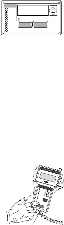
For added service flexibility, an accessory hand-held Navigator™ module is also available. This portable device has an extended communication cable that can be plugged into the unit’s communication network either at the main control box or at the opposite end of the unit, at a remote modular plug. The Navigator display provides the same menu structure, control access and display data as is available at the unit-mounted scrolling marquee display.
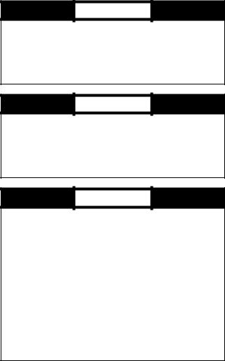
Scrolling Marquee — This device is the keypad interface used to access the control information, read sensor values, and test the unit. The scrolling marquee is located in the main control box and is standard on all units. The scrolling marquee display is a 4-key, 4-character, 16-segment LED (light-emitting diode) display module. The display also contains an Alarm Status LED. See Fig. 1. The display is easy to operate using
MODE |
|
Run Status |
|
Service Test |
|
Temperature |
|
Pressures |
|
Setpoints |
|
Inputs |
Alarm Status |
Outputs |
|
Configuration |
ESCAPE ENTER |
Time Clock |
|
Operating Modes |
|
Alarms |
|
Fig. 1 — Scrolling Marquee
4 buttons and a group of 11 LEDs that indicate the following menu structures:
•Run Status
•Service Test
•Temperatures
•Pressures
•Set points
•Inputs
•Outputs
•Configuration
•Timeclock
•Operating Modes
•Alarms
Through the scrolling marquee, the user can access all of the inputs and outputs to check on their values and status, configure operating parameters plus evaluate the current decision status for operating modes. Because the 48/50Z Series units are equipped with suction pressure and discharge pressure transducers, the scrolling marquee can also display refrigerant circuit pressures typically obtained from service gages. The control also includes an alarm history which can be accessed from the display. In addition, through the scrolling marquee, the user can access a built-in test routine that can be used at start-up commissioning and to diagnose operational problems with the unit.
Accessory Navigator™ Display — The accessory hand-held Navigator display can be used with the 48/50Z Series units. See Fig. 2. The Navigator display operates the same way as the scrolling marquee device. The Navigator display is plugged into the RJ-11 jack in the main control box on the COMM board. The Navigator display can also be plugged into the RJ-11 jack located on the unit corner post located at the economizer end of the unit.
|
|
|
|
|
|
|
Co |
m f |
o r |
t Li n |
|
|||
|
|
|
|
|
|
|
|
|
||||||
|
|
|
|
|
|
|
N A V |
I |
k |
|||||
|
|
|
|
|
|
|
G |
|
||||||
|
|
|
|
|
|
|
|
|
|
A T |
||||
|
|
|
|
T |
IME |
|
|
|
|
|
O R |
|
||
|
|
|
|
1 2 . |
|
|
|
|
||||||
|
|
|
EWT |
|
5 8 |
|
|
|||||||
|
|
|
LW |
T |
|
5 |
4 . |
|
|
|
||||
|
|
|
|
6 |
F |
|
|
|||||||
|
|
SE |
|
4 |
|
|
|
|||||||
|
|
TP |
4 . 1 |
|
|
|||||||||
|
|
|
|
|
4 |
F |
|
|
||||||
|
|
|
|
|
|
|
4 |
. 0 |
|
|
|
|||
|
|
|
|
|
|
|
|
|
|
F |
|
|
|
|
|
|
|
|
|
|
|
|
|
|
|
|
|
|
|
|
|
M O |
D E |
|
|
|
|
|
|
|
|
|||
|
|
|
|
|
|
Ala |
|
|
|
|
|
|
||
|
|
Run |
Status |
|
rm St |
atus |
|
|
||||||
|
|
|
|
|
|
|||||||||
|
|
S |
ervice |
Test |
|
|
|
|
|
|
|
|
||
|
|
T |
|
|
|
|
|
|
|
|
||||
|
|
emperat |
|
|
|
|
|
|
|
|
||||
|
|
Pre |
|
|
|
ures |
|
|
|
|
|
|
|
|
|
|
ssures |
|
|
|
|
|
|
|
|
|
|||
|
Se |
|
|
|
|
|
|
|
|
|
|
|
|
|
|
|
tpoints |
|
|
|
|
|
|
|
|
|
|
||
|
Inputs |
|
|
|
|
|
|
|
|
|
|
|
|
|
|
Ou |
|
|
|
|
|
|
|
|
|
|
|
|
|
|
|
tputs |
|
|
|
|
|
|
|
|
|
|
|
|
|
Con |
|
|
|
|
|
|
|
|
|
|
|
|
|
|
Time |
figur |
ation |
|
|
|
|
|
|
|
|
|
||
|
Clock |
|
|
|
E S C |
|
|
|
|
|
|
|
||
Opera |
|
|
|
|
|
|
|
|
|
|
||||
ting M |
odes |
|
|
|
|
|
|
|
|
|||||
Al |
arms |
|
|
|
|
|
|
|
|
|
||||
|
|
|
|
|
|
|
|
|
|
|
||||
|
ENT |
|
|
|
|
|
|
|
|
|
|
|
|
|
|
|
ER |
|
|
|
|
|
|
|
|
|
|
||
Fig. 2 — Accessory Navigator Display
4

Operation — All units are shipped from the factory with the scrolling marquee display, which is located in the main control box. See Fig. 1. In addition, the ComfortLink™ controls also supports the use of the handheld Navigator™ display.
Both displays provide the user with an interface to the ComfortLink control system. The displays have 
 and
and  arrow keys, an ESCAPE key and an ENTER key. These keys are used to navigate through the different levels of the display structure. The Navigator and the scrolling marquee operate in the same manner, except that the Navigator display has multiple lines of display and the scrolling marquee has a single line. All further discussions and examples in this document will be based on the scrolling marquee display. See Table 2 for the menu structure.
The four keys are used to navigate through the display structure, which is organized in a tiered mode structure. If the buttons have not been used for a period, the display will default to the AUTO VIEW display category as shown under the RUN
STATUS category. To show the top-level display, press the ESCAPE key until a blank display is shown. Then use the
 and
and  arrow keys to scroll through the top-level categories. These are listed in Appendix A and will be indicated on the scrolling marquee by the LED next to each mode listed on the face of the display.
When a specific mode or sub-mode is located, push the ENTER key to enter the mode. Depending on the mode, there may be additional tiers. Continue to use the 
 and
and 
 keys and the ENTER keys until the desired display item is found. At any time, the user can move back a mode level by pressing the ESCAPE key. Once an item has been selected the display will flash showing the item, followed by the item value and then followed by the item units (if any).
Items in the Configuration and Service Test modes are password protected. The display will flash PASS and WORD when required. Use the ENTER and arrow keys to enter the four digits of the password. The default password is 1111.
Pressing the ESCAPE and ENTER keys simultaneously will scroll an expanded text description across the display indicating the full meaning of each display point. Pressing the ESCAPE and ENTER keys when the display is blank (MODE LED level) will return the display to its default menu of rotating AUTO VIEW display items. In addition, the password will need to be entered again before changes can be made.
Changing item values or testing outputs is accomplished in the same manner. Locate and display the desired item. If the display is in rotating auto-view, press the ENTER key to stop the display at the desired item. Press the ENTER key again so that the item value flashes. Use the arrow keys to change the value of state of an item and press the ENTER key to accept it. Press the ESCAPE key and the item, value or units display will resume. Repeat the process as required for other items.
If the user needs to force a variable, follow the same process as when editing a configuration parameter. A forced variable will be displayed with a blinking “f” following its value. For example, if supply fan requested (FAN.F) is forced, the display shows “YESf”, where the “f” is blinking to signify a force on the point. Remove the force by selecting the point that is forced
with the |
ENTER |
key and then pressing the |
and |
arrow keys simultaneously.
Depending on the unit model, factory-installed options and field-installed accessories, some of the items in the various mode categories may not apply.
System Pilot™ Interface — The System Pilot interface (33PILOT-01) is a component of the 3V™ system and serves as a user-interface and configuration tool for all Carrier communicating devices. The System Pilot interface can be used to install and commission a 3V zoning system, linkage compatible air source, universal controller, and all other devices operating on the Carrier communicating network.
Additionally, the System Pilot interface can serve as a wallmounted temperature sensor for space temperature measurement. The occupant can use the System Pilot interface to change set points. A security feature is provided to limit access of features for unauthorized users. See Fig. 3 for System Pilot interface details.
CCN Tables and Display — In addition to the unitmounted scrolling marquee display, the user can also access the same information through the CCN tables by using the Service Tool or other CCN programs. Details on the CCN tables are summarized in Appendix B. The variable names used for the CCN tables and the scrolling marquee tables may be different and more items are displayed in the CCN tables. As a reference, the CCN variable names are included in the scrolling marquee tables and the scrolling marquee names are included in the CCN tables in Appendix B.
GENERIC STATUS DISPLAY TABLE — The GENERICS points table allows the service/installer the ability to create a custom table in which up to 20 points from the 5 CCN categories (Points, Config, Service-Config, Set Point, and Maintenance) may be collected and displayed.
In the Service-Config table section, there is a table named “generics”. This table contains placeholders for up to 20 CCN point names and allows the user to decide which points are displayed in the GENERIC points table. Each one of these placeholders allows the input of an 8-character ASCII string. Go into the Edit mode for the Service-Config table “generics” and enter the CCN name for each point to be displayed in the custom points table in the order they will be displayed. When done entering point names, download the table to the rooftop unit control.
NAVIGATE/ |
MODIFY/ |
EXIT |
SELECT |
SCROLL |
+ |
PAGE |
-
Fig. 3 — System Pilot User Interface
5
Table 2 — Scrolling Marquee Menu Display Structure
RUN |
SERVICE |
TEMPERATURES |
PRESSURES |
SETPOINTS |
INPUTS |
OUTPUTS |
CONFIGURATION |
TIME |
OPERATING |
ALARMS |
|
STATUS |
TEST |
CLOCK |
MODES |
||||||||
|
|
|
|
|
|
|
|||||
Auto View of |
Service Test Mode |
Air |
Air Pressures |
Occupied Heat |
General Inputs |
Fans |
Unit |
Time of Day |
System |
Currently |
|
Run Status |
(TEST) |
Temperatures |
(AIR.P) |
Setpoint |
(GEN.I) |
(FANS) |
Configuration |
(TIME) |
Mode |
Active |
|
(VIEW) |
↓ |
(AIR.T) |
↓ |
(OHSP) |
↓ |
↓ |
(UNIT) |
↓ |
(SYS.M) |
Alarms |
|
↓ |
|
↓ |
|
↓ |
|
|
↓ |
|
↓ |
(CURR) |
|
|
Software |
|
Refrigerant |
|
Compressor |
Cooling |
|
Month, Date, |
|
↓ |
|
Econ |
Command |
Refrigerant |
Pressures |
Occupied Cool |
Feedback |
(COOL) |
Cooling |
Day and Year |
HVAC Mode |
|
|
Run Status |
Disable |
Temperatures |
(REF.P) |
Setpoint |
(FD.BK) |
↓ |
Configuration |
(DATE) |
(HVAC) |
Reset All |
|
(ECON) |
(STOP) |
(REF.T) |
|
(OCSP) |
↓ |
|
(COOL) |
↓ |
↓ |
Current |
|
↓ |
↓ |
|
|
↓ |
|
Heating |
↓ |
|
|
Alarms |
|
|
|
|
|
|
(R.CUR) |
||||||
|
|
|
|
|
Thermostat |
(HEAT) |
|
Local Time |
Control Type |
||
|
|
|
|
|
|
↓ |
|||||
Cooling |
Soft Stop |
|
|
Unoccupied |
Inputs |
|
Evap/Discharge |
Schedule |
(CTRL) |
||
Information |
Request |
|
|
Heat Setpoint |
(STAT) |
Actuators |
Temp. Reset |
(SCH.L) |
↓ |
|
|
(COOL) |
(S.STP) |
|
|
(UHSP) |
↓ |
(ACTU) |
(EDT.R) |
↓ |
|
Alarm |
|
↓ |
↓ |
|
|
↓ |
|
↓ |
↓ |
|
Mode |
History |
|
|
|
|
|
(HIST) |
|||||||
|
|
|
|
|
Fire-Smoke |
|
|
Local |
Controlling |
||
|
|
|
|
|
|
|
|
||||
Mode |
Supply Fan |
|
|
Unoccupied |
Modes |
General |
Heating |
Holiday |
Unit |
|
|
Trip Helper |
Request |
|
|
Cool Setpoint |
(FIRE) |
Outputs |
Configuration |
Schedules |
(MODE) |
|
|
(TRIP) |
(FAN.F) |
|
|
(UCSP) |
↓ |
(GEN.O) |
(HEAT) |
(HOL.L) |
|
|
|
↓ |
↓ |
|
|
↓ |
|
|
↓ |
↓ |
|
|
|
|
|
|
|
|
Relative |
|
|
|
|
|
|
CCN |
Test Independent |
|
|
Heat - Cool |
Humidity |
|
Supply Static |
Daylight |
|
|
|
Linkage |
Outputs |
|
|
Setpoint |
(REL.H) |
|
Press. Config. |
Savings |
|
|
|
(LINK) |
(INDP) |
|
|
(GAP) |
↓ |
|
(SP) |
Time |
|
|
|
↓ |
↓ |
|
|
↓ |
|
|
↓ |
(DAY.S) |
|
|
|
|
|
|
|
|
Air Quality |
|
|
|
|
|
|
Compressor |
Test Fans |
|
|
VAV Occ |
Sensors |
|
Economizer |
|
|
|
|
Run Hours |
(FANS) |
|
|
Cool On |
(AIR.Q) |
|
Configuration |
|
|
|
|
(HRS) |
↓ |
|
|
(V.C.ON) |
↓ |
|
(ECON) |
|
|
|
|
↓ |
|
|
|
↓ |
|
|
↓ |
|
|
|
|
|
Calibrate Test |
|
|
|
CFM Sensors |
|
|
|
|
|
|
Compressor |
Actuators |
|
|
VAV Occ |
(CFM) |
|
Building Press. |
|
|
|
|
Starts |
(ACT.C) |
|
|
Cool Off |
↓ |
|
Configs |
|
|
|
|
(STRT) |
↓ |
|
|
(V.C.OF) |
|
|
(BP) |
|
|
|
|
↓ |
|
|
|
↓ |
Reset Inputs |
|
↓ |
|
|
|
|
|
Test Cooling |
|
|
|
(RSET) |
|
|
|
|
|
|
Software |
(COOL) |
|
|
Supply Air |
↓ |
|
Cool/Heat |
|
|
|
|
Version |
↓ |
|
|
Setpoint |
|
|
Setpt. Offsets |
|
|
|
|
Numbers |
|
|
|
(SASP) |
4-20 Milliamp |
|
(D.L.V.T) |
|
|
|
|
(VERS) |
|
|
|
↓ |
|
↓ |
|
|
|
||
Test Heating |
|
|
Inputs |
|
|
|
|
||||
|
(HEAT) |
|
|
Supply Air |
(4-20) |
|
Demand Limit |
|
|
|
|
|
|
|
|
|
|
|
|
|
|||
|
|
|
|
Setpoint Hi |
|
|
Config. |
|
|
|
|
|
|
|
|
(SA.HI) |
|
|
(DMD.L) |
|
|
|
|
|
|
|
|
↓ |
|
|
↓ |
|
|
|
|
|
|
|
|
Supply Air |
|
|
Indoor Air |
|
|
|
|
|
|
|
|
Setpoint Lo |
|
|
Quality Cfg. |
|
|
|
|
|
|
|
|
(SA.LO) |
|
|
(IAQ) |
|
|
|
|
|
|
|
|
↓ |
|
|
↓ |
|
|
|
|
|
|
|
|
Heating Supply |
|
|
Humidity |
|
|
|
|
|
|
|
|
Air Setpoint |
|
|
Configuration |
|
|
|
|
|
|
|
|
(SA.HT) |
|
|
(HUMD) |
|
|
|
|
|
|
|
|
↓ |
|
|
↓ |
|
|
|
|
|
|
|
|
Tempering |
|
|
Dehumidification |
|
|
|
|
|
|
|
|
Purge SASP |
|
|
Config. |
|
|
|
|
|
|
|
|
(T.PRG) |
|
|
(DEHU) |
|
|
|
|
|
|
|
|
↓ |
|
|
↓ |
|
|
|
|
|
|
|
|
Tempering in |
|
|
CCN |
|
|
|
|
|
|
|
|
Cool SASP |
|
|
Configuration |
|
|
|
|
|
|
|
|
(T.CL) |
|
|
(CCN) |
|
|
|
|
|
|
|
|
↓ |
|
|
↓ |
|
|
|
|
|
|
|
|
Tempering in |
|
|
Alert Limit |
|
|
|
|
|
|
|
|
Vent Occ SASP |
|
|
Config. |
|
|
|
|
|
|
|
|
(T.V.OC) |
|
|
(ALLM) |
|
|
|
|
|
|
|
|
↓ |
|
|
↓ |
|
|
|
|
|
|
|
|
Tempering in |
|
|
Sensor Trim |
|
|
|
|
|
|
|
|
Vent Unocc. |
|
|
Config. |
|
|
|
|
|
|
|
|
SASP |
|
|
(TRIM) |
|
|
|
|
|
|
|
|
(T.V.UN) |
|
|
↓ |
|
|
|
|
|
|
|
|
|
|
|
Switch |
|
|
|
|
|
|
|
|
|
|
|
Logic |
|
|
|
|
|
|
|
|
|
|
|
(SW.LG) |
|
|
|
|
|
|
|
|
|
|
|
↓ |
|
|
|
|
|
|
|
|
|
|
|
Display |
|
|
|
|
|
|
|
|
|
|
|
Configuration |
|
|
|
|
|
|
|
|
|
|
|
(DISP) |
|
|
|
6

IMPORTANT: The computer system software (ComfortVIEW™, Service Tool, etc.) that is used to interact with CCN controls always saves a template of items it considers as static (e.g., limits, units, forcibility, 24-character text strings, and point names) after the software uploads the tables from a control. Thereafter, the software is only concerned with run time data like value and hardware/force status. With this in mind, it is important that anytime a change is made to the Service-Config table “generics” (which in turn changes the points contained in the GENERIC point table), that a complete new upload be performed. This requires that any previous table database be completely removed first. Failure to do this will not allow the user to display the new points that have been created and the software will have a different table database than the unit control.
START-UP
IMPORTANT: Do not attempt to start unit, even momentarily, until all items on the Start-Up Checklist (in installation instructions) and the following steps have been completed.
Unit Preparation — Check that unit has been installed in accordance with the installation instructions and applicable codes.
Unit Setup — Make sure that the economizer hood has been installed and that the outdoor filters are properly installed.
Internal Wiring — Ensure that all electrical connections in the control box are tightened as required. If the unit has staged gas heat make sure that the LAT sensors have been routed to the supply ducts as required.
Accessory Installation — Check to make sure that all accessories including space thermostats and sensors have been installed and wired as required by the instructions and unit wiring diagrams.
Crankcase Heaters — Crankcase heaters are energized as long as there is power to the unit, except when the compressors are running.
IMPORTANT: Unit power must be on for 24 hours prior to start-up of compressors. Otherwise damage to compressors may result.
Evaporator Fan — Fan belt and fixed pulleys are factoryinstalled. See Tables 3-25 for fan performance. Remove tape from fan pulley, and be sure that fans rotate in the proper
direction. See Tables 26-28 for motor limitations. See Table 29 for air quantity limits. Static pressure drop is shown in Tables 30A-30C.
FIELD-SUPPLIED FAN DRIVES — Supply fan and power exhaust fan drives are fixed-pitch, non-adjustable selections, for maximum reliability and long belt life. If the factory drive sets must be changed to obtain other fan speeds, consult the nearest Browning Manufacturing Co. sales office with the required new wheel speed and the data from Physical Data and Supply Fan Drive Data tables (center distances, motor and fan shaft diameters, motor horsepower) in Installation Instructions for a modified drive set selection. For minor speed changes, the fan sheave size should be changed. (Do not reduce the size of the motor sheave; this will result in reduced belt horsepower ratings and reduced belt life.) See page 128 for belt installation procedure.
Controls — Use the following steps for the controls:
1.Set any control configurations that are required (fieldinstalled accessories, etc.). The unit is factory configured for all appropriate factory-installed options.
2.Enter unit set points. The unit is shipped with the set point default values. If a different set point is required, use the scrolling marquee, Navigator display, ComfortVIEW™ software or Service Tool to change the configuration values.
3.If the internal time schedules are going to be used, configure the Occupancy schedule.
4.Verify that the control time periods programmed meet current requirements.
5.Start unit using Service Test mode to verify operation of all major components.
6.If the unit is a VAV unit make sure to configure the static pressure set point. To check out the VFD, use the VFD instructions shipped with the unit.
Gas Heat — Verify gas pressure before turning on gas heat as follows:
1.Turn off field-supplied manual gas stop, located external to the unit.
2.Connect pressure gages to supply gas tap, located at fieldsupplied manual shutoff valves.
3.Connect pressure gages to manifold pressure tap on unit gas valve.
4.Supply gas pressure must not exceed 13.5 in. wg. Check pressure at field-supplied shut-off valve.
5.Turn on manual gas stop and initiate a heating demand. Jumper R to W1 in the control box to initiate heat.
6.Use the Service Test procedure to verify heat operation.
7.After the unit has run for several minutes, verify that incoming pressure is 5.0 in. wg or greater and that the manifold pressure is 3.5 in wg. If manifold pressure must be adjusted refer to Gas Valve Adjustment section.
7

Table 3 — Fan Performance — 48ZG,ZN030 and 50ZG,ZN030 Units Without Discharge Plenum*
AIRFLOW |
|
|
|
|
AVAILABLE EXTERNAL STATIC PRESSURE (in. wg) |
|
|
|
|
||||||||
0.2 |
0.4 |
0.6 |
0.8 |
1.0 |
1.2 |
1.4 |
1.6 |
||||||||||
(Cfm) |
|||||||||||||||||
|
Rpm |
Bhp |
Rpm |
Bhp |
Rpm |
Bhp |
Rpm |
Bhp |
Rpm |
Bhp |
Rpm |
Bhp |
Rpm |
Bhp |
Rpm |
Bhp |
|
6,000 |
222 |
0.59 |
284 |
0.91 |
339 |
1.27 |
388 |
1.66 |
430 |
2.07 |
469 |
2.50 |
504 |
2.93 |
536 |
3.38 |
|
7,500 |
248 |
0.94 |
300 |
1.28 |
350 |
1.68 |
395 |
2.11 |
437 |
2.57 |
475 |
3.05 |
511 |
3.54 |
544 |
4.05 |
|
9,000 |
278 |
1.46 |
323 |
1.80 |
366 |
2.22 |
407 |
2.69 |
446 |
3.19 |
483 |
3.71 |
517 |
4.25 |
550 |
4.81 |
|
10,500 |
311 |
2.16 |
349 |
2.52 |
387 |
2.95 |
424 |
3.43 |
459 |
3.96 |
493 |
4.51 |
526 |
5.10 |
558 |
5.70 |
|
12,000 |
344 |
3.08 |
378 |
3.44 |
412 |
3.89 |
445 |
4.39 |
477 |
4.93 |
508 |
5.51 |
539 |
6.12 |
569 |
6.75 |
|
13,500 |
379 |
4.25 |
410 |
4.62 |
440 |
5.07 |
469 |
5.58 |
498 |
6.13 |
527 |
6.73 |
555 |
7.36 |
583 |
8.02 |
|
15,000 |
415 |
5.69 |
442 |
6.06 |
470 |
6.52 |
496 |
7.04 |
523 |
7.61 |
549 |
8.22 |
575 |
8.87 |
601 |
9.55 |
|
|
|
|
|
|
|
|
|
|
|
|
|
|
|
|
|
|
|
AIRFLOW |
|
|
|
|
AVAILABLE EXTERNAL STATIC PRESSURE (in. wg) |
|
|
|
|
||||||||
1.8 |
2.0 |
2.2 |
2.4 |
2.6 |
2.8 |
3.0 |
3.2 |
||||||||||
(Cfm) |
|||||||||||||||||
|
Rpm |
Bhp |
Rpm |
Bhp |
Rpm |
Bhp |
Rpm |
Bhp |
Rpm |
Bhp |
Rpm |
Bhp |
Rpm |
Bhp |
Rpm |
Bhp |
|
6,000 |
567 |
3.84 |
595 |
4.30 |
622 |
4.78 |
647 |
5.26 |
671 |
5.75 |
695 |
6.25 |
717 |
6.76 |
738 |
7.27 |
|
7,500 |
575 |
4.57 |
604 |
5.10 |
632 |
5.63 |
658 |
6.18 |
683 |
6.73 |
707 |
7.29 |
730 |
7.86 |
752 |
8.43 |
|
9,000 |
581 |
5.38 |
611 |
5.97 |
639 |
6.56 |
665 |
7.16 |
691 |
7.78 |
715 |
8.40 |
739 |
9.03 |
761 |
9.66 |
|
10,500 |
588 |
6.31 |
617 |
6.95 |
645 |
7.59 |
672 |
8.25 |
697 |
8.92 |
722 |
9.59 |
746 |
10.28 |
769 |
10.97 |
|
12,000 |
598 |
7.41 |
625 |
8.08 |
652 |
8.77 |
679 |
9.47 |
704 |
10.19 |
728 |
10.91 |
752 |
11.65 |
775 |
12.39 |
|
13,500 |
610 |
8.71 |
637 |
9.41 |
662 |
10.14 |
687 |
10.88 |
712 |
11.63 |
736 |
12.40 |
759 |
13.18 |
782 |
13.98 |
|
15,000 |
626 |
10.25 |
651 |
10.98 |
675 |
11.74 |
699 |
12.51 |
723 |
13.30 |
746 |
14.10 |
768 |
14.92 |
790 |
15.75 |
|
|
|
|
|
|
|
|
|
|
|
|
|
|
|
|
|
|
|
AIRFLOW |
AVAILABLE EXTERNAL STATIC PRESSURE (in. wg) |
|
|
|
|
|
|
|
|
||||||||
3.4 |
3.6 |
3.8 |
4.0 |
|
|
|
|
|
|
|
|
||||||
(Cfm) |
|
|
|
|
|
|
|
|
|||||||||
|
Rpm |
Bhp |
Rpm |
Bhp |
Rpm |
Bhp |
Rpm |
Bhp |
|
|
|
|
|
|
|
|
|
6,000 |
759 |
7.79 |
779 |
8.32 |
799 |
8.85 |
817 |
9.39 |
|
|
|
|
|
|
|
|
|
7,500 |
773 |
9.01 |
794 |
9.60 |
814 |
10.20 |
833 |
10.80 |
|
|
|
|
|
|
|
|
|
9,000 |
783 |
10.30 |
805 |
10.95 |
825 |
11.60 |
845 |
12.26 |
|
|
|
|
|
|
|
|
|
10,500 |
791 |
11.67 |
812 |
12.38 |
833 |
13.09 |
854 |
13.81 |
|
|
|
|
|
|
|
|
|
12,000 |
797 |
13.15 |
819 |
13.91 |
840 |
14.68 |
860 |
15.45 |
|
|
|
|
|
|
|
|
|
13,500 |
804 |
14.77 |
825 |
15.59 |
846 |
16.41 |
867 |
17.23 |
|
|
|
|
|
|
|
|
|
15,000 |
812 |
16.59 |
833 |
17.45 |
853 |
18.31 |
874 |
19.19 |
|
|
|
|
|
|
|
|
|
LEGEND
48/50ZN units only.
Bhp — Brake Horsepower
*If calculating static pressure for a 48 Series unit, be sure to add gas heat pressure drop from Table 30A on page 32.
NOTES:
1. Fan performance is based on wet coils and clean 2-in. filters.
2.See Table 30A before using Fan Performance tables.
3.Conversion — Bhp to kW:
Kilowatts =
Bhp x .746
Motor efficiency
See Tables 26-28 for motor efficiency.
8

Table 4 — Fan Performance — 48ZG,ZN035 and 50ZG,ZN035 Units Without Discharge Plenum*
AIRFLOW |
|
|
|
|
AVAILABLE EXTERNAL STATIC PRESSURE (in. wg) |
|
|
|
|
||||||||
0.2 |
0.4 |
0.6 |
0.8 |
1.0 |
1.2 |
1.4 |
1.6 |
||||||||||
(Cfm) |
|||||||||||||||||
|
Rpm |
Bhp |
Rpm |
Bhp |
Rpm |
Bhp |
Rpm |
Bhp |
Rpm |
Bhp |
Rpm |
Bhp |
Rpm |
Bhp |
Rpm |
Bhp |
|
7,000 |
246 |
0.84 |
301 |
1.19 |
352 |
1.58 |
398 |
2.01 |
440 |
2.46 |
479 |
2.93 |
514 |
3.40 |
547 |
3.90 |
|
8,000 |
266 |
1.14 |
315 |
1.50 |
362 |
1.92 |
406 |
2.37 |
447 |
2.85 |
484 |
3.35 |
519 |
3.87 |
552 |
4.39 |
|
10,000 |
310 |
1.98 |
350 |
2.36 |
389 |
2.80 |
427 |
3.30 |
464 |
3.83 |
499 |
4.38 |
532 |
4.96 |
564 |
5.55 |
|
12,000 |
357 |
3.20 |
390 |
3.60 |
424 |
4.06 |
457 |
4.58 |
489 |
5.15 |
520 |
5.74 |
551 |
6.36 |
580 |
7.01 |
|
14,000 |
406 |
4.87 |
435 |
5.28 |
463 |
5.76 |
492 |
6.30 |
520 |
6.89 |
548 |
7.52 |
576 |
8.18 |
603 |
8.86 |
|
15,000 |
430 |
5.89 |
458 |
6.31 |
485 |
6.80 |
511 |
7.35 |
538 |
7.95 |
564 |
8.59 |
590 |
9.26 |
616 |
9.96 |
|
|
|
|
|
|
|
|
|
|
|
|
|
|
|
|
|
|
|
AIRFLOW |
|
|
|
|
AVAILABLE EXTERNAL STATIC PRESSURE (in. wg) |
|
|
|
|
||||||||
1.8 |
2.0 |
2.2 |
2.4 |
2.6 |
2.8 |
3.0 |
3.2 |
||||||||||
(Cfm) |
|||||||||||||||||
|
Rpm |
Bhp |
Rpm |
Bhp |
Rpm |
Bhp |
Rpm |
Bhp |
Rpm |
Bhp |
Rpm |
Bhp |
Rpm |
Bhp |
Rpm |
Bhp |
|
7,000 |
577 |
4.40 |
606 |
4.91 |
633 |
5.43 |
659 |
5.95 |
684 |
6.49 |
707 |
7.03 |
730 |
7.58 |
752 |
8.14 |
|
8,000 |
583 |
4.94 |
612 |
5.49 |
640 |
6.05 |
666 |
6.62 |
691 |
7.19 |
715 |
7.78 |
738 |
8.37 |
760 |
8.97 |
|
10,000 |
594 |
6.16 |
623 |
6.79 |
651 |
7.42 |
677 |
8.07 |
703 |
8.73 |
727 |
9.39 |
751 |
10.06 |
774 |
10.74 |
|
12,000 |
609 |
7.67 |
636 |
8.36 |
663 |
9.05 |
689 |
9.77 |
714 |
10.49 |
738 |
11.22 |
762 |
11.97 |
785 |
12.72 |
|
14,000 |
629 |
9.57 |
655 |
10.30 |
680 |
11.04 |
704 |
11.81 |
728 |
12.59 |
751 |
13.38 |
774 |
14.18 |
796 |
14.99 |
|
15,000 |
641 |
10.69 |
666 |
11.44 |
690 |
12.20 |
714 |
12.99 |
737 |
13.79 |
760 |
14.61 |
782 |
15.44 |
804 |
16.28 |
|
|
|
|
|
|
|
|
|
|
|
|
|
|
|
|
|
||
AIRFLOW |
AVAILABLE EXTERNAL STATIC PRESSURE (in. wg) |
|
|
|
|
|
|
|
|
||||||||
3.4 |
3.6 |
3.8 |
4.0 |
|
|
|
|
|
|
|
|
||||||
(Cfm) |
|
|
|
|
|
|
|
|
|||||||||
|
Rpm |
Bhp |
Rpm |
Bhp |
Rpm |
Bhp |
Rpm |
Bhp |
|
|
|
|
|
|
|
|
|
7,000 |
773 |
8.70 |
793 |
9.27 |
813 |
9.85 |
832 |
10.43 |
|
|
|
|
|
|
|
|
|
8,000 |
782 |
9.57 |
802 |
10.18 |
823 |
10.80 |
842 |
11.43 |
|
|
|
|
|
|
|
|
|
10,000 |
796 |
11.42 |
817 |
12.11 |
838 |
12.81 |
858 |
13.52 |
|
|
|
|
|
|
|
|
|
12,000 |
807 |
13.48 |
828 |
14.25 |
849 |
15.02 |
869 |
15.80 |
|
|
|
|
|
|
|
|
|
14,000 |
818 |
15.82 |
840 |
16.66 |
860 |
17.50 |
880 |
18.35 |
|
|
|
|
|
|
|
|
|
15,000 |
825 |
17.13 |
846 |
18.00 |
866 |
18.87 |
886 |
19.76 |
|
|
|
|
|
|
|
|
|
LEGEND
48/50ZN units only.
Bhp — Brake Horsepower
*If calculating static pressure for a 48 Series unit, be sure to add gas heat pressure drop from Table 30A on page 32.
NOTES:
1. Fan performance is based on wet coils and clean 2-in. filters.
2.See Table 30A before using Fan Performance tables.
3.Conversion — Bhp to kW:
Kilowatts =
Bhp x .746
Motor efficiency
See Tables 26-28 for motor efficiency.
9

Table 5 — Fan Performance — 48ZG,ZN040 and 50ZG,ZN040 Units Without Discharge Plenum*
AVAILABLE EXTERNAL STATIC PRESSURE (in. wg)
AIRFLOW |
|
|
|
|
|
|
|
|
|
|
|
|
|
|
|
|
|
|
|
|
|
|
|
|
|
0.2 |
|
0.4 |
|
0.6 |
|
0.8 |
|
1.0 |
|
1.2 |
|
1.4 |
|
1.6 |
|||||||||
(Cfm) |
|
|
|
|
|
|
|
|
||||||||||||||||
|
Rpm |
|
Bhp |
Rpm |
|
Bhp |
Rpm |
|
Bhp |
Rpm |
|
Bhp |
Rpm |
|
Bhp |
Rpm |
|
Bhp |
Rpm |
|
Bhp |
Rpm |
|
Bhp |
8,000 |
252 |
|
0.98 |
303 |
|
1.33 |
350 |
|
1.72 |
394 |
|
2.14 |
434 |
|
2.58 |
472 |
|
3.06 |
507 |
|
3.55 |
540 |
|
4.07 |
10,000 |
290 |
|
1.67 |
333 |
|
2.11 |
373 |
|
2.55 |
412 |
|
3.01 |
448 |
|
3.51 |
483 |
|
4.03 |
517 |
|
4.58 |
549 |
|
5.16 |
12,000 |
330 |
|
2.65 |
369 |
|
3.18 |
404 |
|
3.70 |
438 |
|
4.23 |
470 |
|
4.78 |
501 |
|
5.35 |
532 |
|
5.94 |
562 |
|
6.56 |
14,000 |
372 |
|
3.96 |
407 |
|
4.61 |
439 |
|
5.22 |
469 |
|
5.83 |
498 |
|
6.44 |
526 |
|
7.07 |
554 |
|
7.72 |
581 |
|
8.38 |
16,000 |
415 |
|
5.67 |
447 |
|
6.44 |
476 |
|
7.15 |
504 |
|
7.85 |
530 |
|
8.54 |
556 |
|
9.24 |
581 |
|
9.95 |
605 |
|
10.67 |
18,000 |
459 |
|
7.84 |
488 |
|
8.72 |
515 |
|
9.55 |
541 |
|
10.34 |
565 |
|
11.12 |
589 |
|
11.91 |
612 |
|
12.69 |
634 |
|
13.47 |
20,000 |
503 |
|
10.51 |
530 |
|
11.51 |
555 |
|
12.46 |
579 |
|
13.36 |
602 |
|
14.24 |
624 |
|
15.11 |
645 |
|
15.98 |
666 |
|
16.84 |
|
|
|
|
|
|
|
|
|
|
|
|
|
|
|
|
|
||||||||
AIRFLOW |
|
|
|
|
|
|
AVAILABLE EXTERNAL STATIC PRESSURE (in. wg) |
|
|
|
|
|
|
|||||||||||
|
1.8 |
|
2.0 |
|
2.2 |
|
2.4 |
|
2.6 |
|
2.8 |
|
3.0 |
|
3.2 |
|||||||||
(Cfm) |
|
|
|
|
|
|
|
|
||||||||||||||||
|
Rpm |
|
Bhp |
Rpm |
|
Bhp |
Rpm |
|
Bhp |
Rpm |
|
Bhp |
Rpm |
|
Bhp |
Rpm |
|
Bhp |
Rpm |
|
Bhp |
Rpm |
|
Bhp |
8,000 |
571 |
|
4.60 |
600 |
|
5.14 |
628 |
|
5.70 |
654 |
|
6.27 |
679 |
|
6.85 |
703 |
|
7.44 |
726 |
|
8.04 |
748 |
|
8.65 |
10,000 |
579 |
|
5.75 |
608 |
|
6.36 |
636 |
|
6.98 |
662 |
|
7.62 |
688 |
|
8.28 |
712 |
|
8.94 |
736 |
|
9.62 |
758 |
|
10.30 |
12,000 |
590 |
|
7.21 |
618 |
|
7.87 |
645 |
|
8.55 |
671 |
|
9.25 |
696 |
|
9.96 |
720 |
|
10.69 |
744 |
|
11.43 |
766 |
|
12.19 |
14,000 |
607 |
|
9.07 |
633 |
|
9.78 |
658 |
|
10.51 |
683 |
|
11.25 |
707 |
|
12.02 |
730 |
|
12.80 |
753 |
|
13.60 |
775 |
|
14.41 |
16,000 |
629 |
|
11.41 |
653 |
|
12.16 |
676 |
|
12.94 |
699 |
|
13.73 |
722 |
|
14.54 |
744 |
|
15.37 |
766 |
|
16.22 |
787 |
|
17.08 |
18,000 |
656 |
|
14.28 |
678 |
|
15.09 |
700 |
|
15.91 |
721 |
|
16.76 |
742 |
|
17.62 |
762 |
|
18.49 |
783 |
|
19.39 |
803 |
|
20.29 |
20,000 |
687 |
|
17.71 |
707 |
|
18.60 |
727 |
|
19.48 |
747 |
|
20.38 |
766 |
|
21.30 |
785 |
|
22.22 |
804 |
|
23.17 |
— |
|
— |
|
|
|
|
|
|
|
|
|
|
|
|
|
|
|
|
|
|
|
|
|||||
AIRFLOW |
AVAILABLE EXTERNAL STATIC PRESSURE (in. wg) |
|
|
|
|
|
|
|
|
|
|
|
|
|||||||||||
|
3.4 |
|
3.6 |
|
3.8 |
|
4.0 |
|
|
|
|
|
|
|
|
|
|
|
|
|||||
(Cfm) |
|
|
|
|
|
|
|
|
|
|
|
|
|
|
|
|
||||||||
|
Rpm |
|
Bhp |
Rpm |
|
Bhp |
Rpm |
|
Bhp |
Rpm |
|
Bhp |
|
|
|
|
|
|
|
|
|
|
|
|
8,000 |
770 |
|
9.27 |
791 |
|
9.90 |
811 |
|
10.54 |
830 |
|
11.18 |
|
|
|
|
|
|
|
|
|
|
|
|
10,000 |
780 |
|
11.00 |
802 |
|
11.71 |
822 |
|
12.43 |
842 |
|
13.15 |
|
|
|
|
|
|
|
|
|
|
|
|
12,000 |
789 |
|
12.96 |
810 |
|
13.73 |
831 |
|
14.52 |
851 |
|
15.32 |
|
|
|
|
|
|
|
|
|
|
|
|
14,000 |
797 |
|
15.24 |
818 |
|
16.07 |
839 |
|
16.93 |
859 |
|
17.79 |
|
|
|
|
|
|
|
|
|
|
|
|
16,000 |
808 |
|
17.95 |
828 |
|
18.85 |
849 |
|
19.75 |
868 |
|
20.67 |
|
|
|
|
|
|
|
|
|
|
|
|
18,000 |
823 |
|
21.21 |
842 |
|
22.15 |
862 |
|
23.11 |
— |
|
— |
|
|
|
|
|
|
|
|
|
|
|
|
20,000 |
— |
|
— |
— |
|
— |
— |
|
— |
— |
|
— |
|
|
|
|
|
|
|
|
|
|
|
|
LEGEND
48/50ZN units only.
Bhp — Brake Horsepower
*If calculating static pressure for a 48 Series unit, be sure to add gas heat pressure drop from Table 30A on page 32.
NOTES:
1. Fan performance is based on wet coils and clean 2-in. filters.
2.See Table 30A before using Fan Performance tables.
3.Conversion — Bhp to kW:
Bhp x .746
Kilowatts = Motor efficiency
See Tables 26-28 for motor efficiency.
10
Table 6 — Fan Performance — 48ZG,ZN050 and 50ZG,ZN050 Units Without Discharge Plenum*
AVAILABLE EXTERNAL STATIC PRESSURE (in. wg)
AIRFLOW |
|
|
|
|
|
|
|
|
|
|
|
|
|
|
|
|
|
|
|
|
|
|
|
|
|
0.2 |
|
0.4 |
|
0.6 |
|
0.8 |
|
1.0 |
|
1.2 |
|
1.4 |
|
1.6 |
|||||||||
(Cfm) |
|
|
|
|
|
|
|
|
||||||||||||||||
|
Rpm |
|
Bhp |
Rpm |
|
Bhp |
Rpm |
|
Bhp |
Rpm |
|
Bhp |
Rpm |
|
Bhp |
Rpm |
|
Bhp |
Rpm |
|
Bhp |
Rpm |
|
Bhp |
9,000 |
276 |
|
1.34 |
323 |
|
1.73 |
366 |
|
2.15 |
407 |
|
2.60 |
445 |
|
3.08 |
482 |
|
3.58 |
516 |
|
4.11 |
549 |
|
4.66 |
10,000 |
296 |
|
1.74 |
339 |
|
2.17 |
379 |
|
2.62 |
418 |
|
3.09 |
454 |
|
3.59 |
489 |
|
4.12 |
522 |
|
4.68 |
554 |
|
5.26 |
12,000 |
339 |
|
2.76 |
376 |
|
3.29 |
411 |
|
3.81 |
445 |
|
4.35 |
477 |
|
4.91 |
509 |
|
5.49 |
539 |
|
6.09 |
568 |
|
6.71 |
14,000 |
382 |
|
4.15 |
416 |
|
4.79 |
448 |
|
5.40 |
478 |
|
6.01 |
506 |
|
6.63 |
535 |
|
7.26 |
562 |
|
7.92 |
589 |
|
8.60 |
16,000 |
427 |
|
5.96 |
458 |
|
6.71 |
487 |
|
7.42 |
514 |
|
8.11 |
540 |
|
8.81 |
565 |
|
9.52 |
590 |
|
10.23 |
615 |
|
10.97 |
18,000 |
473 |
|
8.26 |
501 |
|
9.12 |
527 |
|
9.93 |
552 |
|
10.72 |
576 |
|
11.50 |
600 |
|
12.29 |
623 |
|
13.08 |
645 |
|
13.88 |
20,000 |
519 |
|
11.10 |
545 |
|
12.06 |
570 |
|
12.99 |
593 |
|
13.88 |
615 |
|
14.76 |
637 |
|
15.63 |
658 |
|
16.50 |
679 |
|
17.38 |
|
|
|
|
|
|
|
|
|
|
|
|
|
|
|
|
|
||||||||
AIRFLOW |
|
|
|
|
|
|
AVAILABLE EXTERNAL STATIC PRESSURE (in. wg) |
|
|
|
|
|
|
|||||||||||
|
1.8 |
|
2.0 |
|
2.2 |
|
2.4 |
|
2.6 |
|
2.8 |
|
3.0 |
|
3.2 |
|||||||||
(Cfm) |
|
|
|
|
|
|
|
|
||||||||||||||||
|
Rpm |
|
Bhp |
Rpm |
|
Bhp |
Rpm |
|
Bhp |
Rpm |
|
Bhp |
Rpm |
|
Bhp |
Rpm |
|
Bhp |
Rpm |
|
Bhp |
Rpm |
|
Bhp |
9,000 |
579 |
|
5.23 |
608 |
|
5.81 |
636 |
|
6.41 |
662 |
|
7.02 |
687 |
|
7.64 |
712 |
|
8.27 |
735 |
|
8.91 |
757 |
|
9.57 |
10,000 |
584 |
|
5.85 |
613 |
|
6.47 |
641 |
|
7.10 |
667 |
|
7.74 |
692 |
|
8.40 |
717 |
|
9.07 |
740 |
|
9.75 |
763 |
|
10.44 |
12,000 |
597 |
|
7.36 |
625 |
|
8.03 |
651 |
|
8.72 |
677 |
|
9.42 |
702 |
|
10.14 |
726 |
|
10.88 |
750 |
|
11.63 |
772 |
|
12.39 |
14,000 |
615 |
|
9.29 |
641 |
|
10.01 |
666 |
|
10.74 |
690 |
|
11.50 |
714 |
|
12.27 |
738 |
|
13.06 |
760 |
|
13.87 |
783 |
|
14.69 |
16,000 |
639 |
|
11.71 |
663 |
|
12.48 |
686 |
|
13.27 |
709 |
|
14.07 |
731 |
|
14.89 |
753 |
|
15.73 |
775 |
|
16.58 |
796 |
|
17.45 |
18,000 |
667 |
|
14.69 |
689 |
|
15.51 |
711 |
|
16.35 |
732 |
|
17.20 |
753 |
|
18.07 |
773 |
|
18.96 |
793 |
|
19.86 |
813 |
|
20.78 |
20,000 |
699 |
|
18.25 |
719 |
|
19.14 |
739 |
|
20.04 |
759 |
|
20.95 |
778 |
|
21.88 |
797 |
|
22.82 |
816 |
|
23.77 |
— |
|
— |
|
|
|
|
|
|
|
|
|
|
|
|
|
|
|
|
|
|
|
|
|||||
AIRFLOW |
AVAILABLE EXTERNAL STATIC PRESSURE (in. wg) |
|
|
|
|
|
|
|
|
|
|
|
|
|||||||||||
|
3.4 |
|
3.6 |
|
3.8 |
|
4.0 |
|
|
|
|
|
|
|
|
|
|
|
|
|||||
(Cfm) |
|
|
|
|
|
|
|
|
|
|
|
|
|
|
|
|
||||||||
|
Rpm |
|
Bhp |
Rpm |
|
Bhp |
Rpm |
|
Bhp |
Rpm |
|
Bhp |
|
|
|
|
|
|
|
|
|
|
|
|
9,000 |
779 |
|
10.23 |
800 |
|
10.90 |
821 |
|
11.58 |
840 |
|
12.27 |
|
|
|
|
|
|
|
|
|
|
|
|
10,000 |
785 |
|
11.14 |
806 |
|
11.85 |
826 |
|
12.57 |
846 |
|
13.30 |
|
|
|
|
|
|
|
|
|
|
|
|
12,000 |
794 |
|
13.16 |
816 |
|
13.94 |
836 |
|
14.73 |
857 |
|
15.54 |
|
|
|
|
|
|
|
|
|
|
|
|
14,000 |
804 |
|
15.52 |
825 |
|
16.37 |
846 |
|
17.22 |
866 |
|
18.10 |
|
|
|
|
|
|
|
|
|
|
|
|
16,000 |
817 |
|
18.34 |
837 |
|
19.24 |
857 |
|
20.15 |
877 |
|
21.08 |
|
|
|
|
|
|
|
|
|
|
|
|
18,000 |
833 |
|
21.71 |
853 |
|
22.66 |
872 |
|
23.62 |
— |
|
— |
|
|
|
|
|
|
|
|
|
|
|
|
20,000 |
— |
|
— |
— |
|
— |
— |
|
— |
— |
|
— |
|
|
|
|
|
|
|
|
|
|
|
|
LEGEND
48/50ZN units only.
Bhp — Brake Horsepower
*If calculating static pressure for a 48 Series unit, be sure to add gas heat pressure drop from Table 30A on page 32.
NOTES:
1. Fan performance is based on wet coils and clean 2-in. filters.
2.See Table 30A before using Fan Performance tables.
3.Conversion — Bhp to kW:
Kilowatts =
Bhp x .746
Motor efficiency
See Tables 26-28 for motor efficiency.
11

Table 7 — Fan Performance — 48ZG,ZN055 and 50ZG,ZN055 Units Without Discharge Plenum*
AVAILABLE EXTERNAL STATIC PRESSURE (in. wg)
AIRFLOW |
|
|
|
|
|
|
|
|
|
|
|
|
|
|
|
|
|
|
|
|
|
|
|
0.2 |
0.4 |
0.6 |
0.8 |
1.0 |
1.2 |
|
1.4 |
|
1.6 |
||||||||||||||
(Cfm) |
|
|
|||||||||||||||||||||
|
Rpm |
|
Bhp |
|
Rpm |
|
Bhp |
Rpm |
Bhp |
Rpm |
Bhp |
Rpm |
|
Bhp |
|
Rpm |
Bhp |
Rpm |
|
Bhp |
Rpm |
|
Bhp |
10,000 |
207 |
|
1.04 |
253 |
1.50 |
295 |
2.03 |
334 |
2.66 |
371 |
3.41 |
405 |
4.26 |
438 |
|
5.20 |
468 |
|
6.20 |
||||
12,500 |
235 |
|
1.69 |
276 |
2.23 |
312 |
2.78 |
346 |
3.40 |
379 |
4.10 |
410 |
4.88 |
440 |
|
5.75 |
469 |
|
6.70 |
||||
15,000 |
265 |
|
2.59 |
302 |
3.23 |
335 |
3.85 |
365 |
4.51 |
394 |
5.20 |
422 |
5.96 |
449 |
|
6.78 |
476 |
|
7.67 |
||||
17,500 |
295 |
|
3.78 |
331 |
4.52 |
361 |
5.24 |
389 |
5.97 |
415 |
6.71 |
440 |
7.48 |
465 |
|
8.30 |
489 |
|
9.17 |
||||
20,000 |
327 |
|
5.31 |
360 |
6.15 |
388 |
6.98 |
414 |
7.79 |
439 |
8.60 |
462 |
9.43 |
485 |
|
10.28 |
507 |
|
11.17 |
||||
22,500 |
359 |
|
7.23 |
390 |
8.16 |
417 |
9.09 |
442 |
10.00 |
465 |
10.90 |
487 |
11.81 |
508 |
|
12.72 |
528 |
|
13.65 |
||||
25,000 |
392 |
|
9.59 |
421 |
10.60 |
447 |
11.62 |
470 |
12.64 |
492 |
13.64 |
513 |
14.63 |
533 |
|
15.62 |
552 |
|
16.62 |
||||
|
|
|
|
|
|
|
|
|
|
|
|
|
|
|
|
|
|
|
|
|
|
||
AIRFLOW |
|
|
|
|
|
|
|
AVAILABLE EXTERNAL STATIC PRESSURE (in. wg) |
|
|
|
|
|
|
|||||||||
|
1.8 |
|
|
2.0 |
|
2.2 |
|
2.4 |
|
2.6 |
|
|
2.8 |
|
3.0 |
|
3.2 |
||||||
(Cfm) |
|
|
|
|
|
|
|
|
|
|
|||||||||||||
|
Rpm |
|
Bhp |
|
Rpm |
|
Bhp |
Rpm |
Bhp |
Rpm |
Bhp |
Rpm |
|
Bhp |
|
Rpm |
Bhp |
Rpm |
|
Bhp |
Rpm |
|
Bhp |
10,000 |
497 |
|
7.27 |
|
523 |
|
8.39 |
549 |
9.55 |
573 |
10.75 |
596 |
|
11.98 |
|
618 |
13.23 |
639 |
|
14.51 |
659 |
|
15.81 |
12,500 |
497 |
|
7.73 |
|
523 |
|
8.83 |
549 |
10.00 |
573 |
11.22 |
597 |
|
12.49 |
|
619 |
13.81 |
641 |
|
15.16 |
662 |
|
16.55 |
15,000 |
501 |
|
8.63 |
|
526 |
|
9.67 |
550 |
10.77 |
574 |
11.94 |
597 |
|
13.17 |
|
619 |
14.46 |
641 |
|
15.80 |
662 |
|
17.19 |
17,500 |
512 |
|
10.09 |
|
535 |
|
11.07 |
557 |
12.11 |
579 |
13.21 |
601 |
|
14.38 |
|
622 |
15.60 |
643 |
|
16.88 |
663 |
|
18.21 |
20,000 |
528 |
|
12.09 |
|
549 |
|
13.06 |
570 |
14.07 |
590 |
15.12 |
610 |
|
16.24 |
|
630 |
17.40 |
649 |
|
18.62 |
668 |
|
19.89 |
22,500 |
548 |
|
14.60 |
|
567 |
|
15.59 |
587 |
16.61 |
605 |
17.66 |
624 |
|
18.75 |
|
642 |
19.88 |
660 |
|
21.06 |
678 |
|
22.28 |
25,000 |
571 |
|
17.63 |
|
589 |
|
18.66 |
607 |
19.71 |
624 |
20.78 |
642 |
|
21.89 |
|
659 |
23.02 |
676 |
|
24.19 |
692 |
|
25.39 |
|
|
|
|
|
|
|
|
|
|
|
|
|
|
|
|
|
|
|
|
|
|||
AIRFLOW |
AVAILABLE EXTERNAL STATIC PRESSURE (in. wg) |
|
|
|
|
|
|
|
|
|
|
|
|
||||||||||
|
3.4 |
|
|
3.6 |
|
3.8 |
|
4.0 |
|
|
|
|
|
|
|
|
|
|
|
|
|||
(Cfm) |
|
|
|
|
|
|
|
|
|
|
|
|
|
|
|
|
|
||||||
|
Rpm |
|
Bhp |
|
Rpm |
|
Bhp |
Rpm |
Bhp |
Rpm |
Bhp |
|
|
|
|
|
|
|
|
|
|
|
|
10,000 |
679 |
|
17.13 |
|
697 |
|
18.46 |
715 |
19.81 |
733 |
21.17 |
|
|
|
|
|
|
|
|
|
|
|
|
12,500 |
682 |
|
17.98 |
|
702 |
|
19.43 |
721 |
20.90 |
739 |
22.40 |
|
|
|
|
|
|
|
|
|
|
|
|
15,000 |
682 |
|
18.63 |
|
702 |
|
20.10 |
721 |
21.62 |
740 |
23.17 |
|
|
|
|
|
|
|
|
|
|
|
|
17,500 |
683 |
|
19.60 |
|
702 |
|
21.04 |
721 |
22.53 |
740 |
24.06 |
|
|
|
|
|
|
|
|
|
|
|
|
20,000 |
687 |
|
21.20 |
|
706 |
|
22.57 |
724 |
24.00 |
742 |
25.46 |
|
|
|
|
|
|
|
|
|
|
|
|
22,500 |
696 |
|
23.55 |
|
713 |
|
24.86 |
731 |
26.22 |
748 |
27.62 |
|
|
|
|
|
|
|
|
|
|
|
|
25,000 |
709 |
|
26.62 |
|
725 |
|
27.91 |
741 |
29.22 |
— |
— |
|
|
|
|
|
|
|
|
|
|
|
|
LEGEND
48/50ZN units only.
Bhp — Brake Horsepower
*If calculating static pressure for a 48 Series unit, be sure to add gas heat pressure drop from Table 30B on page 32.
NOTES:
1. Fan performance is based on wet coils and clean 2-in. filters.
2.See Table 30B before using Fan Performance tables.
3.Conversion — Bhp to kW:
Bhp x .746
Kilowatts = Motor efficiency
See Tables 26-28 for motor efficiency.
12

Table 8 — Fan Performance — 48ZG,ZN060 and 50ZG,ZN060 Units Without Discharge Plenum*
AVAILABLE EXTERNAL STATIC PRESSURE (in. wg)
AIRFLOW |
|
|
|
|
|
|
|
|
|
|
|
|
|
|
|
|
|
|
|
|
|
|
|
|
|
0.2 |
|
0.4 |
|
0.6 |
|
0.8 |
|
1.0 |
|
1.2 |
|
1.4 |
|
1.6 |
|||||||||
(Cfm) |
|
|
|
|
|
|
|
|
||||||||||||||||
|
Rpm |
|
Bhp |
Rpm |
|
Bhp |
Rpm |
|
Bhp |
Rpm |
|
Bhp |
Rpm |
|
Bhp |
Rpm |
|
Bhp |
Rpm |
|
Bhp |
Rpm |
|
Bhp |
12,000 |
234 |
|
1.54 |
276 |
|
2.03 |
312 |
|
2.57 |
348 |
|
3.20 |
382 |
|
3.93 |
415 |
|
4.74 |
446 |
|
5.63 |
476 |
|
6.58 |
15,000 |
271 |
|
2.65 |
309 |
|
3.27 |
341 |
|
3.88 |
370 |
|
4.53 |
399 |
|
5.24 |
428 |
|
6.04 |
455 |
|
6.91 |
482 |
|
7.85 |
18,000 |
308 |
|
4.22 |
344 |
|
5.00 |
374 |
|
5.73 |
400 |
|
6.46 |
426 |
|
7.22 |
450 |
|
8.02 |
474 |
|
8.88 |
498 |
|
9.81 |
21,000 |
348 |
|
6.36 |
380 |
|
7.29 |
408 |
|
8.18 |
434 |
|
9.04 |
457 |
|
9.88 |
479 |
|
10.74 |
501 |
|
11.64 |
522 |
|
12.58 |
24,000 |
390 |
|
9.19 |
417 |
|
10.24 |
444 |
|
11.29 |
469 |
|
12.29 |
491 |
|
13.27 |
512 |
|
14.23 |
532 |
|
15.21 |
551 |
|
16.20 |
27,000 |
433 |
|
12.80 |
456 |
|
13.93 |
481 |
|
15.14 |
504 |
|
16.30 |
526 |
|
17.44 |
546 |
|
18.53 |
565 |
|
19.62 |
583 |
|
20.71 |
30,000 |
476 |
|
17.29 |
497 |
|
18.50 |
519 |
|
19.82 |
541 |
|
21.15 |
562 |
|
22.45 |
581 |
|
23.70 |
599 |
|
24.93 |
617 |
|
26.14 |
|
|
|
|
|
|
|
|
|
|
|
|
|
|
|
||||||||||
AIRFLOW |
|
|
|
|
|
|
AVAILABLE EXTERNAL STATIC PRESSURE (in. wg) |
|
|
|
|
|
|
|||||||||||
|
1.8 |
|
2.0 |
|
2.2 |
|
2.4 |
|
2.6 |
|
2.8 |
|
3.0 |
|
3.2 |
|||||||||
(Cfm) |
|
|
|
|
|
|
|
|
||||||||||||||||
|
Rpm |
|
Bhp |
Rpm |
|
Bhp |
Rpm |
|
Bhp |
Rpm |
|
Bhp |
Rpm |
|
Bhp |
Rpm |
|
Bhp |
Rpm |
|
Bhp |
Rpm |
|
Bhp |
12,000 |
504 |
|
7.56 |
530 |
|
8.57 |
555 |
|
9.61 |
578 |
|
10.66 |
600 |
|
11.73 |
621 |
|
12.81 |
641 |
|
13.91 |
660 |
|
15.01 |
15,000 |
509 |
|
8.87 |
535 |
|
9.95 |
559 |
|
11.07 |
583 |
|
12.25 |
606 |
|
13.45 |
628 |
|
14.68 |
650 |
|
15.95 |
670 |
|
17.23 |
18,000 |
521 |
|
10.79 |
544 |
|
11.85 |
567 |
|
12.97 |
590 |
|
14.14 |
612 |
|
15.38 |
633 |
|
16.66 |
654 |
|
17.99 |
675 |
|
19.36 |
21,000 |
543 |
|
13.56 |
563 |
|
14.60 |
583 |
|
15.69 |
603 |
|
16.84 |
623 |
|
18.05 |
643 |
|
19.31 |
662 |
|
20.63 |
682 |
|
21.99 |
24,000 |
570 |
|
17.22 |
588 |
|
18.28 |
607 |
|
19.39 |
625 |
|
20.53 |
642 |
|
21.72 |
660 |
|
22.95 |
678 |
|
24.24 |
695 |
|
25.58 |
27,000 |
601 |
|
21.81 |
618 |
|
22.93 |
635 |
|
24.07 |
651 |
|
25.25 |
667 |
|
26.46 |
684 |
|
27.70 |
700 |
|
28.98 |
715 |
|
30.31 |
30,000 |
634 |
|
27.34 |
650 |
|
28.56 |
666 |
|
29.78 |
681 |
|
31.02 |
696 |
|
32.28 |
711 |
|
33.56 |
726 |
|
34.88 |
—- |
|
— |
|
|
|
|
|
|
|
|
|
|
|
|
|
|
|
|
|
|
|
||||||
AIRFLOW |
AVAILABLE EXTERNAL STATIC PRESSURE (in. wg) |
|
|
|
|
|
|
|
|
|
|
|
|
|||||||||||
|
3.4 |
|
3.6 |
|
3.8 |
|
4.0 |
|
|
|
|
|
|
|
|
|
|
|
|
|||||
(Cfm) |
|
|
|
|
|
|
|
|
|
|
|
|
|
|
|
|
||||||||
|
Rpm |
|
Bhp |
Rpm |
|
Bhp |
Rpm |
|
Bhp |
Rpm |
|
Bhp |
|
|
|
|
|
|
|
|
|
|
|
|
12,000 |
679 |
|
16.11 |
697 |
|
17.23 |
714 |
|
18.35 |
730 |
|
19.49 |
|
|
|
|
|
|
|
|
|
|
|
|
15,000 |
690 |
|
18.52 |
709 |
|
19.84 |
727 |
|
21.15 |
745 |
|
22.49 |
|
|
|
|
|
|
|
|
|
|
|
|
18,000 |
695 |
|
20.76 |
714 |
|
22.20 |
733 |
|
23.66 |
— |
|
— |
|
|
|
|
|
|
|
|
|
|
|
|
21,000 |
701 |
|
23.41 |
719 |
|
24.87 |
738 |
|
26.38 |
— |
|
— |
|
|
|
|
|
|
|
|
|
|
|
|
24,000 |
713 |
|
26.97 |
730 |
|
28.40 |
747 |
|
29.89 |
— |
|
— |
|
|
|
|
|
|
|
|
|
|
|
|
27,000 |
731 |
|
31.67 |
747 |
|
33.08 |
—- |
|
— |
— |
|
— |
|
|
|
|
|
|
|
|
|
|
|
|
30,000 |
— |
|
— |
— |
|
— |
— |
|
— |
— |
|
— |
|
|
|
|
|
|
|
|
|
|
|
|
LEGEND
48/50ZN units only.
Bhp — Brake Horsepower
*If calculating static pressure for a 48 Series unit, be sure to add gas heat pressure drop from Table 30B on page 32.
NOTES:
1. Fan performance is based on wet coils and clean 2-in. filters.
2.See Table 30B before using Fan Performance tables.
3.Conversion — Bhp to kW:
Kilowatts =
Bhp x .746
Motor efficiency
See Tables 26-28 for motor efficiency.
13

Table 9 — Fan Performance — 48ZG,ZN070 and 50ZG,ZN070 Units Without Discharge Plenum*
AVAILABLE EXTERNAL STATIC PRESSURE (in. wg)
AIRFLOW |
|
|
|
|
|
|
|
|
|
|
|
|
|
|
|
|
|
|
|
|
|
|
|
|
|
0.2 |
|
0.4 |
|
0.6 |
|
0.8 |
|
1.0 |
|
1.2 |
|
1.4 |
|
1.6 |
|||||||||
(Cfm) |
|
|
|
|
|
|
|
|
||||||||||||||||
|
Rpm |
|
Bhp |
Rpm |
|
Bhp |
Rpm |
|
Bhp |
Rpm |
|
Bhp |
Rpm |
|
Bhp |
Rpm |
|
Bhp |
Rpm |
|
Bhp |
Rpm |
|
Bhp |
14,000 |
258 |
|
2.23 |
297 |
|
2.80 |
330 |
|
3.38 |
362 |
|
4.02 |
392 |
|
4.73 |
422 |
|
5.53 |
451 |
|
6.42 |
480 |
|
7.37 |
17,500 |
302 |
|
3.92 |
338 |
|
4.67 |
368 |
|
5.39 |
395 |
|
6.10 |
421 |
|
6.84 |
446 |
|
7.64 |
471 |
|
8.50 |
495 |
|
9.42 |
21,000 |
348 |
|
6.36 |
380 |
|
7.29 |
408 |
|
8.18 |
434 |
|
9.04 |
457 |
|
9.88 |
479 |
|
10.74 |
501 |
|
11.64 |
522 |
|
12.57 |
24,500 |
397 |
|
9.74 |
424 |
|
10.80 |
450 |
|
11.88 |
475 |
|
12.91 |
497 |
|
13.91 |
517 |
|
14.89 |
537 |
|
15.88 |
556 |
|
16.89 |
28,000 |
447 |
|
14.18 |
470 |
|
15.35 |
494 |
|
16.60 |
516 |
|
17.82 |
538 |
|
19.01 |
558 |
|
20.16 |
576 |
|
21.29 |
594 |
|
22.41 |
30,000 |
476 |
|
17.29 |
497 |
|
18.50 |
519 |
|
19.82 |
541 |
|
21.15 |
562 |
|
22.45 |
581 |
|
23.70 |
599 |
|
24.93 |
617 |
|
26.14 |
|
|
|
|
|
|
|
|
|
|
|
|
|
|
|
|
|
||||||||
AIRFLOW |
|
|
|
|
|
|
AVAILABLE EXTERNAL STATIC PRESSURE (in. wg) |
|
|
|
|
|
|
|||||||||||
|
1.8 |
|
2.0 |
|
2.2 |
|
2.4 |
|
2.6 |
|
2.8 |
|
3.0 |
|
3.2 |
|||||||||
(Cfm) |
|
|
|
|
|
|
|
|
||||||||||||||||
|
Rpm |
|
Bhp |
Rpm |
|
Bhp |
Rpm |
|
Bhp |
Rpm |
|
Bhp |
Rpm |
|
Bhp |
Rpm |
|
Bhp |
Rpm |
|
Bhp |
Rpm |
|
Bhp |
14,000 |
507 |
|
8.39 |
533 |
|
9.46 |
558 |
|
10.57 |
582 |
|
11.71 |
605 |
|
12.89 |
627 |
|
14.08 |
648 |
|
15.29 |
668 |
|
16.52 |
17,500 |
519 |
|
10.42 |
542 |
|
11.48 |
565 |
|
12.60 |
588 |
|
13.78 |
610 |
|
15.02 |
632 |
|
16.30 |
653 |
|
17.62 |
674 |
|
18.99 |
21,000 |
543 |
|
13.56 |
563 |
|
14.60 |
583 |
|
15.69 |
603 |
|
16.84 |
623 |
|
18.05 |
643 |
|
19.31 |
662 |
|
20.63 |
682 |
|
21.99 |
24,500 |
575 |
|
17.93 |
593 |
|
18.99 |
611 |
|
20.10 |
629 |
|
21.24 |
646 |
|
22.43 |
664 |
|
23.67 |
681 |
|
24.96 |
698 |
|
26.29 |
28,000 |
612 |
|
23.55 |
628 |
|
24.69 |
645 |
|
25.86 |
661 |
|
27.05 |
677 |
|
28.27 |
692 |
|
29.53 |
708 |
|
30.82 |
723 |
|
32.15 |
30,000 |
634 |
|
27.34 |
650 |
|
28.56 |
666 |
|
29.78 |
681 |
|
31.02 |
696 |
|
32.28 |
711 |
|
33.56 |
726 |
|
34.88 |
— |
|
— |
|
|
|
|
|
|
|
|
|
|
|
|
|
|
|
|
|
|
|
|
|
||||
AIRFLOW |
AVAILABLE EXTERNAL STATIC PRESSURE (in. wg) |
|
|
|
|
|
|
|
|
|
|
|
|
|||||||||||
|
3.4 |
|
3.6 |
|
3.8 |
|
4.0 |
|
|
|
|
|
|
|
|
|
|
|
|
|||||
(Cfm) |
|
|
|
|
|
|
|
|
|
|
|
|
|
|
|
|
||||||||
|
Rpm |
|
Bhp |
Rpm |
|
Bhp |
Rpm |
|
Bhp |
Rpm |
|
Bhp |
|
|
|
|
|
|
|
|
|
|
|
|
14,000 |
687 |
|
17.76 |
706 |
|
19.01 |
724 |
|
20.27 |
741 |
|
21.54 |
|
|
|
|
|
|
|
|
|
|
|
|
17,500 |
694 |
|
20.38 |
713 |
|
21.79 |
732 |
|
23.24 |
— |
|
— |
|
|
|
|
|
|
|
|
|
|
|
|
21,000 |
701 |
|
23.41 |
719 |
|
24.87 |
738 |
|
26.38 |
— |
|
— |
|
|
|
|
|
|
|
|
|
|
|
|
24,500 |
715 |
|
27.67 |
732 |
|
29.10 |
749 |
|
30.58 |
— |
|
— |
|
|
|
|
|
|
|
|
|
|
|
|
28,000 |
739 |
|
33.51 |
— |
|
— |
— |
|
— |
— |
|
— |
|
|
|
|
|
|
|
|
|
|
|
|
30,000 |
— |
|
— |
— |
|
— |
— |
|
— |
— |
|
— |
|
|
|
|
|
|
|
|
|
|
|
|
LEGEND
48/50ZN units only.
Bhp — Brake Horsepower
*If calculating static pressure for a 48 Series unit, be sure to add gas heat pressure drop from Table 30B on page 32.
NOTES:
1. Fan performance is based on wet coils and clean 2-in. filters.
2.See Table 30B before using Fan Performance tables.
3.Conversion — Bhp to kW:
Bhp x .746
Kilowatts = Motor efficiency
See Tables 26-28 for motor efficiency.
14

Table 10 — Fan Performance — 50ZG,ZN030 Units With Discharge Plenum and 50Z2,Z3030 Units
AIRFLOW |
|
|
|
|
|
|
AVAILABLE EXTERNAL STATIC PRESSURE (in. wg) |
|
|
|
|
|
|
||||||||||||||||||||||
0.2 |
0.4 |
|
0.6 |
|
|
0.8 |
|
|
|
1.0 |
|
|
|
1.2 |
|
|
1.4 |
1.6 |
|||||||||||||||||
(Cfm) |
|
|
|
|
|
|
|
|
|
|
|
||||||||||||||||||||||||
|
Rpm |
|
Bhp |
Rpm |
Bhp |
|
Rpm |
|
Bhp |
|
Rpm |
|
Bhp |
Rpm |
|
|
Bhp |
|
Rpm |
|
|
Bhp |
|
Rpm |
|
Bhp |
Rpm |
Bhp |
|||||||
6,000 |
255 |
|
0.95 |
313 |
1.35 |
|
364 |
1.82 |
|
411 |
|
2.35 |
|
454 |
|
|
2.92 |
|
494 |
|
3.52 |
|
530 |
4.14 |
563 |
4.78 |
|||||||||
7,500 |
291 |
|
1.51 |
340 |
1.93 |
|
386 |
2.41 |
|
428 |
|
2.94 |
|
468 |
|
|
3.51 |
|
505 |
|
4.13 |
|
541 |
4.78 |
574 |
5.46 |
|||||||||
9,000 |
330 |
|
2.28 |
372 |
2.73 |
|
413 |
3.22 |
|
451 |
|
3.76 |
|
487 |
|
|
4.34 |
|
522 |
|
4.96 |
|
555 |
5.61 |
587 |
6.30 |
|||||||||
10,500 |
371 |
|
3.28 |
408 |
3.76 |
|
444 |
4.28 |
|
479 |
|
4.84 |
|
512 |
|
|
5.43 |
|
544 |
|
6.06 |
|
574 |
6.71 |
604 |
7.40 |
|||||||||
12,000 |
413 |
|
4.56 |
447 |
5.07 |
|
479 |
5.61 |
|
510 |
|
6.19 |
|
540 |
|
|
6.80 |
|
570 |
|
7.44 |
|
598 |
8.11 |
626 |
8.80 |
|||||||||
13,500 |
456 |
|
6.12 |
487 |
6.66 |
|
516 |
7.23 |
|
544 |
|
7.83 |
|
572 |
|
|
8.46 |
|
599 |
|
9.12 |
|
626 |
9.81 |
651 |
10.51 |
|||||||||
15,000 |
500 |
|
7.99 |
528 |
8.58 |
|
555 |
9.18 |
|
581 |
|
9.80 |
|
606 |
|
10.45 |
|
631 |
|
11.13 |
|
656 |
11.83 |
680 |
12.56 |
||||||||||
|
|
|
|
|
|
|
|
|
|
|
|
|
|
|
|
|
|
|
|
|
|||||||||||||||
AIRFLOW |
|
|
|
|
|
|
AVAILABLE EXTERNAL STATIC PRESSURE (in. wg) |
|
|
|
|
|
|
||||||||||||||||||||||
|
1.8 |
|
2.0 |
|
|
2.2 |
|
|
|
|
2.4 |
|
|
|
|
|
2.6 |
|
|
|
|
2.8 |
|
|
|
3.0 |
|
3.2 |
|||||||
(Cfm) |
|
|
|
|
|
|
|
|
|
|
|
|
|
|
|
|
|
|
|
|
|
||||||||||||||
|
Rpm |
|
Bhp |
Rpm |
Bhp |
Rpm |
|
Bhp |
|
Rpm |
|
Bhp |
|
Rpm |
|
Bhp |
|
Rpm |
|
Bhp |
|
Rpm |
|
Bhp |
Rpm |
Bhp |
|||||||||
6,000 |
594 |
|
5.43 |
623 |
6.09 |
651 |
|
6.75 |
|
676 |
|
7.41 |
|
701 |
|
|
8.08 |
|
725 |
|
8.75 |
|
747 |
|
9.42 |
769 |
10.10 |
||||||||
7,500 |
605 |
|
6.16 |
635 |
6.88 |
664 |
|
7.62 |
|
691 |
|
8.36 |
|
716 |
|
|
9.11 |
|
741 |
|
9.88 |
|
765 |
|
10.64 |
787 |
11.41 |
||||||||
9,000 |
617 |
|
7.02 |
646 |
7.76 |
674 |
|
8.52 |
|
702 |
|
9.31 |
|
728 |
|
|
10.11 |
|
753 |
|
10.93 |
|
777 |
|
11.76 |
800 |
12.60 |
||||||||
10,500 |
633 |
|
8.12 |
660 |
8.86 |
687 |
|
9.64 |
|
713 |
|
10.43 |
|
739 |
|
|
11.25 |
|
764 |
|
12.09 |
|
788 |
|
12.95 |
811 |
13.82 |
||||||||
12,000 |
652 |
|
9.52 |
679 |
10.27 |
704 |
|
11.04 |
|
729 |
|
11.84 |
|
753 |
|
|
12.66 |
|
777 |
|
13.50 |
|
800 |
|
14.37 |
823 |
15.26 |
||||||||
13,500 |
676 |
|
11.25 |
701 |
12.00 |
725 |
|
12.78 |
|
748 |
|
13.58 |
|
771 |
|
|
14.40 |
|
794 |
|
15.24 |
|
816 |
|
16.11 |
838 |
16.99 |
||||||||
15,000 |
703 |
|
13.30 |
726 |
14.07 |
749 |
|
14.86 |
|
771 |
|
15.66 |
|
793 |
|
|
16.49 |
|
814 |
|
17.34 |
|
835 |
|
18.20 |
856 |
19.09 |
||||||||
|
|
|
|
|
|
|
|
|
|
|
|
|
|
|
|
|
|
|
|
|
|
|
|
|
|
|
|||||||||
AIRFLOW |
AVAILABLE EXTERNAL STATIC PRESSURE (in. wg) |
|
|
|
|
|
|
|
|
|
|
|
|
|
|
|
|
|
|
|
|||||||||||||||
3.4 |
|
3.6 |
|
|
3.8 |
|
|
4.0 |
|
|
|
|
|
|
|
|
|
|
|
|
|
|
|
|
|
|
|
|
|||||||
(Cfm) |
|
|
|
|
|
|
|
|
|
|
|
|
|
|
|
|
|
|
|
|
|
|
|
|
|
||||||||||
|
Rpm |
|
Bhp |
Rpm |
Bhp |
Rpm |
|
Bhp |
|
Rpm |
|
Bhp |
|
|
|
|
|
|
|
|
|
|
|
|
|
|
|
|
|
|
|
||||
6,000 |
789 |
|
10.77 |
809 |
11.45 |
|
829 |
|
12.13 |
|
848 |
|
12.81 |
|
|
|
|
|
|
|
|
|
|
|
|
|
|
|
|
|
|
|
|||
7,500 |
809 |
|
12.18 |
830 |
12.96 |
|
851 |
|
13.73 |
|
870 |
|
14.51 |
|
|
|
|
|
|
|
|
|
|
|
|
|
|
|
|
|
|
|
|||
9,000 |
823 |
|
13.44 |
844 |
14.29 |
|
866 |
|
15.15 |
|
886 |
|
16.01 |
|
|
|
|
|
|
|
|
|
|
|
|
|
|
|
|
|
|
|
|||
10,500 |
833 |
|
14.71 |
856 |
15.61 |
|
877 |
|
16.52 |
|
898 |
|
17.44 |
|
|
|
|
|
|
|
|
|
|
|
|
|
|
|
|
|
|
|
|||
12,000 |
845 |
|
16.16 |
867 |
17.08 |
|
888 |
|
18.01 |
|
— |
|
— |
|
|
|
|
|
|
|
|
|
|
|
|
|
|
|
|
|
|
|
|||
13,500 |
859 |
|
17.90 |
880 |
18.82 |
|
— |
|
— |
|
— |
|
— |
|
|
|
|
|
|
|
|
|
|
|
|
|
|
|
|
|
|
|
|||
15,000 |
876 |
|
20.00 |
896 |
20.92 |
|
— |
|
— |
|
— |
|
— |
|
|
|
|
|
|
|
|
|
|
|
|
|
|
|
|
|
|
|
|||
LEGEND
50ZN,Z3 units only.
Bhp — Brake Horsepower
NOTES:
1. Fan performance is based on wet coils and clean 2-in. filters.
2.See Table 30A before using Fan Performance tables.
3.Conversion — Bhp to kW:
Kilowatts =
Bhp x .746
Motor efficiency
See Tables 26-28 for motor efficiency.
15

Table 11 — Fan Performance — 50ZG,ZN035 Units With Discharge Plenum and 50Z2,Z3035 Units
AVAILABLE EXTERNAL STATIC PRESSURE (in. wg)
AIRFLOW |
|
|
|
|
|
|
|
|
|
|
|
|
|
|
|
|
|
|
|
|
|
|
|
|
|
|
|
|
|
|
|
0.2 |
0.4 |
|
0.6 |
|
|
0.8 |
|
|
1.0 |
|
|
1.2 |
1.4 |
|
1.6 |
||||||||||||||||
(Cfm) |
|
|
|
|
|
|
|
|
|||||||||||||||||||||||
|
Rpm |
Bhp |
Rpm |
Bhp |
|
Rpm |
|
Bhp |
|
Rpm |
|
|
Bhp |
|
Rpm |
|
|
Bhp |
|
Rpm |
|
Bhp |
|
Rpm |
Bhp |
Rpm |
|
Bhp |
|||
7,000 |
285 |
1.35 |
337 |
1.78 |
|
384 |
2.26 |
|
428 |
|
2.80 |
|
469 |
|
3.38 |
|
507 |
4.00 |
542 |
4.66 |
576 |
|
5.34 |
||||||||
8,000 |
311 |
1.81 |
358 |
2.25 |
|
402 |
2.75 |
|
442 |
|
3.29 |
|
481 |
|
3.87 |
|
517 |
4.50 |
551 |
5.16 |
584 |
|
5.86 |
||||||||
10,000 |
367 |
3.04 |
406 |
3.52 |
|
443 |
4.05 |
|
479 |
|
4.61 |
|
512 |
|
5.21 |
|
545 |
5.84 |
576 |
6.51 |
606 |
|
7.21 |
||||||||
12,000 |
426 |
4.74 |
459 |
5.26 |
|
491 |
5.82 |
|
522 |
|
6.42 |
|
552 |
|
7.05 |
|
581 |
7.70 |
609 |
8.38 |
637 |
|
9.09 |
||||||||
14,000 |
486 |
6.98 |
515 |
7.55 |
|
543 |
8.15 |
|
570 |
|
8.78 |
|
597 |
|
9.44 |
|
623 |
10.12 |
649 |
10.83 |
674 |
|
11.55 |
||||||||
15,000 |
517 |
8.33 |
544 |
8.92 |
|
570 |
9.54 |
|
596 |
|
10.18 |
|
621 |
|
10.85 |
|
646 |
11.55 |
671 |
12.27 |
694 |
|
13.01 |
||||||||
|
|
|
|
|
|
|
|
|
|
|
|
|
|
|
|
|
|
|
|
||||||||||||
AIRFLOW |
|
|
|
|
|
AVAILABLE EXTERNAL STATIC PRESSURE (in. wg) |
|
|
|
|
|
|
|||||||||||||||||||
1.8 |
|
2.0 |
|
|
2.2 |
|
|
|
|
2.4 |
|
|
|
|
2.6 |
|
|
|
2.8 |
|
|
3.0 |
|
3.2 |
|||||||
(Cfm) |
|
|
|
|
|
|
|
|
|
|
|
|
|
|
|
|
|
||||||||||||||
|
Rpm |
Bhp |
Rpm |
Bhp |
Rpm |
|
Bhp |
|
Rpm |
|
Bhp |
|
Rpm |
|
Bhp |
|
Rpm |
|
Bhp |
|
Rpm |
Bhp |
Rpm |
|
Bhp |
||||||
7,000 |
607 |
6.03 |
637 |
6.74 |
665 |
|
7.46 |
|
691 |
|
8.18 |
|
717 |
|
|
8.91 |
|
741 |
|
9.65 |
|
764 |
10.39 |
786 |
|
11.13 |
|||||
8,000 |
615 |
6.58 |
645 |
7.32 |
673 |
|
8.07 |
|
700 |
|
8.84 |
|
726 |
|
|
9.62 |
|
751 |
|
10.41 |
|
775 |
11.20 |
797 |
|
12.00 |
|||||
10,000 |
636 |
7.94 |
664 |
8.70 |
691 |
|
9.48 |
|
717 |
|
10.29 |
|
743 |
|
|
11.11 |
|
768 |
|
11.96 |
|
792 |
12.82 |
815 |
|
13.69 |
|||||
12,000 |
663 |
9.83 |
689 |
10.59 |
715 |
|
11.38 |
|
739 |
|
12.19 |
|
764 |
|
|
13.03 |
|
787 |
|
13.88 |
|
810 |
14.76 |
833 |
|
15.66 |
|||||
14,000 |
698 |
12.31 |
722 |
13.08 |
745 |
|
13.88 |
|
768 |
|
14.69 |
|
791 |
|
|
15.53 |
|
813 |
|
16.39 |
|
834 |
17.27 |
856 |
|
18.17 |
|||||
15,000 |
718 |
13.78 |
741 |
14.56 |
763 |
|
15.36 |
|
785 |
|
16.19 |
|
807 |
|
|
17.03 |
|
828 |
|
17.90 |
|
849 |
18.78 |
869 |
|
19.69 |
|||||
|
|
|
|
|
|
|
|
|
|
|
|
|
|
|
|
|
|
|
|
|
|
|
|
||||||||
AIRFLOW |
AVAILABLE EXTERNAL STATIC PRESSURE (in. wg) |
|
|
|
|
|
|
|
|
|
|
|
|
|
|
|
|
||||||||||||||
3.4 |
|
3.6 |
|
|
3.8 |
|
|
|
|
4.0 |
|
|
|
|
|
|
|
|
|
|
|
|
|
|
|
|
|
||||
(Cfm) |
|
|
|
|
|
|
|
|
|
|
|
|
|
|
|
|
|
|
|
|
|
|
|
|
|||||||
|
Rpm |
Bhp |
Rpm |
Bhp |
Rpm |
|
Bhp |
|
Rpm |
|
Bhp |
|
|
|
|
|
|
|
|
|
|
|
|
|
|
|
|
||||
7,000 |
807 |
11.88 |
828 |
12.62 |
848 |
|
13.37 |
|
867 |
|
14.12 |
|
|
|
|
|
|
|
|
|
|
|
|
|
|
|
|
||||
8,000 |
819 |
12.80 |
841 |
13.61 |
861 |
|
14.42 |
|
881 |
|
15.23 |
|
|
|
|
|
|
|
|
|
|
|
|
|
|
|
|
||||
10,000 |
837 |
14.57 |
859 |
15.47 |
881 |
|
16.37 |
|
—- |
|
— |
|
|
|
|
|
|
|
|
|
|
|
|
|
|
|
|
||||
12,000 |
855 |
16.57 |
876 |
17.51 |
897 |
|
18.45 |
|
— |
|
— |
|
|
|
|
|
|
|
|
|
|
|
|
|
|
|
|
||||
14,000 |
876 |
19.10 |
897 |
20.04 |
— |
|
— |
|
— |
|
— |
|
|
|
|
|
|
|
|
|
|
|
|
|
|
|
|
||||
15,000 |
890 |
20.61 |
— |
— |
— |
|
— |
|
— |
|
— |
|
|
|
|
|
|
|
|
|
|
|
|
|
|
|
|
||||
LEGEND
50ZN,Z3 units only.
Bhp — Brake Horsepower
NOTES:
1. Fan performance is based on wet coils and clean 2-in. filters.
2.See Table 30A before using Fan Performance tables.
3.Conversion — Bhp to kW:
Bhp x .746
Kilowatts = Motor efficiency
See Tables 26-28 for motor efficiency.
16

Table 12 — Fan Performance — 50ZG,ZN040 Units With Discharge Plenum and 50Z2,Z3040 Units
AVAILABLE EXTERNAL STATIC PRESSURE (in. wg)
AIRFLOW |
|
|
|
|
|
|
|
|
|
|
|
|
|
|
|
|
|
|
|
|
|
|
|
|
|
0.2 |
|
0.4 |
|
0.6 |
|
0.8 |
|
1.0 |
|
1.2 |
|
1.4 |
|
1.6 |
|||||||||
(Cfm) |
|
|
|
|
|
|
|
|
||||||||||||||||
|
Rpm |
|
Bhp |
Rpm |
|
Bhp |
Rpm |
|
Bhp |
Rpm |
|
Bhp |
Rpm |
|
Bhp |
Rpm |
|
Bhp |
Rpm |
|
Bhp |
Rpm |
|
Bhp |
8,000 |
293 |
|
1.62 |
344 |
|
2.10 |
390 |
|
2.62 |
432 |
|
3.18 |
470 |
|
3.76 |
507 |
|
4.36 |
541 |
|
4.97 |
573 |
|
5.60 |
10,000 |
343 |
|
2.66 |
385 |
|
3.19 |
425 |
|
3.76 |
463 |
|
4.36 |
498 |
|
4.99 |
532 |
|
5.64 |
563 |
|
6.31 |
594 |
|
7.00 |
12,000 |
395 |
|
4.09 |
431 |
|
4.68 |
466 |
|
5.29 |
500 |
|
5.93 |
532 |
|
6.60 |
562 |
|
7.30 |
592 |
|
8.01 |
620 |
|
8.75 |
14,000 |
449 |
|
5.97 |
481 |
|
6.62 |
512 |
|
7.28 |
541 |
|
7.96 |
570 |
|
8.67 |
598 |
|
9.40 |
626 |
|
10.16 |
652 |
|
10.93 |
16,000 |
504 |
|
8.32 |
533 |
|
9.06 |
560 |
|
9.77 |
587 |
|
10.50 |
613 |
|
11.25 |
638 |
|
12.02 |
663 |
|
12.81 |
688 |
|
13.62 |
18,000 |
559 |
|
11.20 |
586 |
|
12.04 |
611 |
|
12.82 |
635 |
|
13.59 |
659 |
|
14.38 |
682 |
|
15.19 |
705 |
|
16.01 |
727 |
|
16.86 |
20,000 |
615 |
|
14.66 |
640 |
|
15.59 |
663 |
|
16.44 |
685 |
|
17.28 |
707 |
|
18.11 |
728 |
|
18.96 |
749 |
|
19.83 |
770 |
|
20.71 |
|
|
|
|
|
|
|
|
|
|
|
|
|
|
|
|
|
||||||||
AIRFLOW |
|
|
|
|
|
|
AVAILABLE EXTERNAL STATIC PRESSURE (in. wg) |
|
|
|
|
|
|
|||||||||||
|
1.8 |
|
2.0 |
|
2.2 |
|
2.4 |
|
2.6 |
|
2.8 |
|
3.0 |
|
3.2 |
|||||||||
(Cfm) |
|
|
|
|
|
|
|
|
||||||||||||||||
|
Rpm |
|
Bhp |
Rpm |
|
Bhp |
Rpm |
|
Bhp |
Rpm |
|
Bhp |
Rpm |
|
Bhp |
Rpm |
|
Bhp |
Rpm |
|
Bhp |
Rpm |
|
Bhp |
8,000 |
603 |
|
6.23 |
632 |
|
6.87 |
659 |
|
7.50 |
685 |
|
8.14 |
710 |
|
8.78 |
734 |
|
9.43 |
757 |
|
10.07 |
779 |
|
10.71 |
10,000 |
623 |
|
7.70 |
651 |
|
8.41 |
678 |
|
9.13 |
703 |
|
9.86 |
728 |
|
10.60 |
752 |
|
11.33 |
776 |
|
12.08 |
798 |
|
12.82 |
12,000 |
648 |
|
9.50 |
674 |
|
10.26 |
699 |
|
11.04 |
724 |
|
11.83 |
748 |
|
12.63 |
772 |
|
13.44 |
794 |
|
14.25 |
817 |
|
15.07 |
14,000 |
677 |
|
11.73 |
702 |
|
12.54 |
726 |
|
13.35 |
750 |
|
14.19 |
772 |
|
15.04 |
795 |
|
15.89 |
817 |
|
16.76 |
838 |
|
17.64 |
16,000 |
712 |
|
14.45 |
735 |
|
15.30 |
757 |
|
16.16 |
779 |
|
17.03 |
801 |
|
17.92 |
822 |
|
18.82 |
843 |
|
19.73 |
863 |
|
20.65 |
18,000 |
749 |
|
17.73 |
771 |
|
18.61 |
792 |
|
19.50 |
813 |
|
20.42 |
833 |
|
21.34 |
853 |
|
22.27 |
873 |
|
23.23 |
— |
|
— |
20,000 |
790 |
|
21.61 |
811 |
|
22.52 |
830 |
|
23.45 |
— |
|
— |
— |
|
— |
— |
|
— |
— |
|
— |
— |
|
— |
|
|
|
|
|
|
|
|
|
|
|
|
|
|
|
|
|
|
|
|
|||||
AIRFLOW |
AVAILABLE EXTERNAL STATIC PRESSURE (in. wg) |
|
|
|
|
|
|
|
|
|
|
|
|
|||||||||||
|
3.4 |
|
3.6 |
|
3.8 |
|
4.0 |
|
|
|
|
|
|
|
|
|
|
|
|
|||||
(Cfm) |
|
|
|
|
|
|
|
|
|
|
|
|
|
|
|
|
||||||||
|
Rpm |
|
Bhp |
Rpm |
|
Bhp |
Rpm |
|
Bhp |
Rpm |
|
Bhp |
|
|
|
|
|
|
|
|
|
|
|
|
8,000 |
800 |
|
11.35 |
821 |
|
12.00 |
841 |
|
12.64 |
860 |
|
13.28 |
|
|
|
|
|
|
|
|
|
|
|
|
10,000 |
820 |
|
13.57 |
841 |
|
14.31 |
862 |
|
15.06 |
882 |
|
15.81 |
|
|
|
|
|
|
|
|
|
|
|
|
12,000 |
838 |
|
15.90 |
859 |
|
16.73 |
880 |
|
17.57 |
900 |
|
18.40 |
|
|
|
|
|
|
|
|
|
|
|
|
14,000 |
859 |
|
18.53 |
879 |
|
19.42 |
899 |
|
20.32 |
— |
|
— |
|
|
|
|
|
|
|
|
|
|
|
|
16,000 |
883 |
|
21.58 |
— |
|
— |
— |
|
— |
— |
|
— |
|
|
|
|
|
|
|
|
|
|
|
|
18,000 |
— |
|
— |
— |
|
— |
— |
|
— |
— |
|
— |
|
|
|
|
|
|
|
|
|
|
|
|
20,000 |
— |
|
— |
— |
|
— |
— |
|
— |
— |
|
— |
|
|
|
|
|
|
|
|
|
|
|
|
LEGEND
50ZN,Z3 units only.
Bhp — Brake Horsepower
NOTES:
1. Fan performance is based on wet coils and clean 2-in. filters.
2.See Table 30A before using Fan Performance tables.
3.Conversion — Bhp to kW:
Kilowatts =
Bhp x .746
Motor efficiency
See Tables 26-28 for motor efficiency.
17

Table 13 — Fan Performance — 50ZG,ZN050 Units With Discharge Plenum and 50Z2,Z3050 Units
AVAILABLE EXTERNAL STATIC PRESSURE (in. wg)
AIRFLOW |
|
|
|
|
|
|
|
|
|
|
|
|
|
|
|
|
|
|
|
|
|
|
|
|
|
0.2 |
|
0.4 |
|
0.6 |
|
0.8 |
|
1.0 |
|
1.2 |
|
1.4 |
|
1.6 |
|||||||||
(Cfm) |
|
|
|
|
|
|
|
|
||||||||||||||||
|
Rpm |
|
Bhp |
Rpm |
|
Bhp |
Rpm |
|
Bhp |
Rpm |
|
Bhp |
Rpm |
|
Bhp |
Rpm |
|
Bhp |
Rpm |
|
Bhp |
Rpm |
|
Bhp |
9,000 |
324 |
|
2.15 |
369 |
|
2.67 |
412 |
|
3.23 |
452 |
|
3.83 |
488 |
|
4.44 |
523 |
|
5.08 |
556 |
|
5.73 |
587 |
|
6.40 |
10,000 |
349 |
|
2.74 |
392 |
|
3.28 |
431 |
|
3.87 |
469 |
|
4.48 |
504 |
|
5.12 |
537 |
|
5.78 |
569 |
|
6.46 |
599 |
|
7.16 |
12,000 |
403 |
|
4.23 |
439 |
|
4.82 |
474 |
|
5.45 |
507 |
|
6.11 |
539 |
|
6.80 |
570 |
|
7.51 |
599 |
|
8.23 |
627 |
|
8.98 |
14,000 |
459 |
|
6.17 |
490 |
|
6.83 |
521 |
|
7.50 |
550 |
|
8.20 |
579 |
|
8.93 |
607 |
|
9.69 |
634 |
|
10.46 |
660 |
|
11.25 |
16,000 |
515 |
|
8.63 |
544 |
|
9.34 |
571 |
|
10.07 |
597 |
|
10.82 |
623 |
|
11.59 |
649 |
|
12.38 |
674 |
|
13.20 |
698 |
|
14.03 |
18,000 |
573 |
|
11.65 |
599 |
|
12.44 |
623 |
|
13.21 |
647 |
|
14.00 |
671 |
|
14.82 |
694 |
|
15.65 |
716 |
|
16.50 |
739 |
|
17.37 |
20,000 |
630 |
|
15.28 |
654 |
|
16.14 |
677 |
|
16.97 |
699 |
|
17.81 |
720 |
|
18.66 |
741 |
|
19.53 |
762 |
|
20.43 |
783 |
|
21.34 |
|
|
|
|
|
|
|
|
|
|
|
|
|
|
|
|
|
||||||||
AIRFLOW |
|
|
|
|
|
|
AVAILABLE EXTERNAL STATIC PRESSURE (in. wg) |
|
|
|
|
|
|
|||||||||||
|
1.8 |
|
2.0 |
|
2.2 |
|
2.4 |
|
2.6 |
|
2.8 |
|
3.0 |
|
3.2 |
|||||||||
(Cfm) |
|
|
|
|
|
|
|
|
||||||||||||||||
|
Rpm |
|
Bhp |
Rpm |
|
Bhp |
Rpm |
|
Bhp |
Rpm |
|
Bhp |
Rpm |
|
Bhp |
Rpm |
|
Bhp |
Rpm |
|
Bhp |
Rpm |
|
Bhp |
9,000 |
617 |
|
7.08 |
645 |
|
7.77 |
672 |
|
8.47 |
698 |
|
9.18 |
723 |
|
9.90 |
747 |
|
10.62 |
770 |
|
11.34 |
793 |
|
12.07 |
10,000 |
628 |
|
7.87 |
656 |
|
8.59 |
682 |
|
9.33 |
708 |
|
10.07 |
733 |
|
10.82 |
757 |
|
11.58 |
780 |
|
12.35 |
802 |
|
13.12 |
12,000 |
654 |
|
9.74 |
680 |
|
10.51 |
706 |
|
11.30 |
730 |
|
12.10 |
754 |
|
12.90 |
778 |
|
13.73 |
800 |
|
14.56 |
822 |
|
15.39 |
14,000 |
686 |
|
12.06 |
710 |
|
12.88 |
734 |
|
13.71 |
757 |
|
14.55 |
780 |
|
15.41 |
802 |
|
16.27 |
824 |
|
17.15 |
845 |
|
18.04 |
16,000 |
721 |
|
14.88 |
744 |
|
15.74 |
767 |
|
16.62 |
789 |
|
17.51 |
810 |
|
18.41 |
831 |
|
19.32 |
852 |
|
20.24 |
872 |
|
21.17 |
18,000 |
761 |
|
18.27 |
782 |
|
19.17 |
803 |
|
20.09 |
824 |
|
21.02 |
844 |
|
21.96 |
864 |
|
22.92 |
884 |
|
23.88 |
— |
|
— |
20,000 |
803 |
|
22.27 |
823 |
|
23.21 |
— |
|
— |
— |
|
— |
— |
|
— |
— |
|
— |
— |
|
— |
— |
|
— |
|
|
|
|
|
|
|
|
|
|
|
|
|
|
|
|
|
|
|
|
|||||
AIRFLOW |
AVAILABLE EXTERNAL STATIC PRESSURE (in. wg) |
|
|
|
|
|
|
|
|
|
|
|
|
|||||||||||
|
3.4 |
|
3.6 |
|
3.8 |
|
4.0 |
|
|
|
|
|
|
|
|
|
|
|
|
|||||
(Cfm) |
|
|
|
|
|
|
|
|
|
|
|
|
|
|
|
|
||||||||
|
Rpm |
|
Bhp |
Rpm |
|
Bhp |
Rpm |
|
Bhp |
Rpm |
|
Bhp |
|
|
|
|
|
|
|
|
|
|
|
|
9,000 |
814 |
|
12.79 |
835 |
|
13.52 |
855 |
|
14.25 |
875 |
|
14.99 |
|
|
|
|
|
|
|
|
|
|
|
|
10,000 |
824 |
|
13.89 |
845 |
|
14.67 |
866 |
|
15.45 |
886 |
|
16.23 |
|
|
|
|
|
|
|
|
|
|
|
|
12,000 |
844 |
|
16.24 |
865 |
|
17.09 |
885 |
|
17.95 |
— |
|
— |
|
|
|
|
|
|
|
|
|
|
|
|
14,000 |
866 |
|
18.94 |
886 |
|
19.85 |
— |
|
— |
— |
|
— |
|
|
|
|
|
|
|
|
|
|
|
|
16,000 |
892 |
|
22.12 |
— |
|
— |
— |
|
— |
— |
|
— |
|
|
|
|
|
|
|
|
|
|
|
|
18,000 |
— |
|
— |
— |
|
— |
— |
|
— |
— |
|
— |
|
|
|
|
|
|
|
|
|
|
|
|
20,000 |
— |
|
— |
— |
|
— |
— |
|
— |
— |
|
— |
|
|
|
|
|
|
|
|
|
|
|
|
LEGEND
50ZN,Z3 units only.
Bhp — Brake Horsepower
NOTES:
1. Fan performance is based on wet coils and clean 2-in. filters.
2.See Table 30A before using Fan Performance tables.
3.Conversion — Bhp to kW:
Bhp x .746
Kilowatts = Motor efficiency
See Tables 26-28 for motor efficiency.
18

Table 14 — Fan Performance — 50ZG,ZN055 Units With Discharge Plenum and 50Z2,Z3055 Units
AVAILABLE EXTERNAL STATIC PRESSURE (in. wg)
AIRFLOW |
|
|
|
|
|
|
|
|
|
|
|
|
|
|
|
|
|
|
|
|
|
|
|
|
|
0.2 |
|
0.4 |
|
0.6 |
|
0.8 |
|
1.0 |
|
1.2 |
|
1.4 |
|
1.6 |
|||||||||
(Cfm) |
|
|
|
|
|
|
|
|
||||||||||||||||
|
Rpm |
|
Bhp |
Rpm |
|
Bhp |
Rpm |
|
Bhp |
Rpm |
|
Bhp |
Rpm |
|
Bhp |
Rpm |
|
Bhp |
Rpm |
|
Bhp |
Rpm |
|
Bhp |
10,000 |
217 |
|
1.21 |
258 |
|
1.71 |
296 |
|
2.29 |
334 |
|
2.97 |
371 |
|
3.76 |
407 |
|
4.63 |
440 |
|
5.56 |
471 |
|
6.51 |
12,500 |
248 |
|
2.01 |
286 |
|
2.63 |
319 |
|
3.26 |
349 |
|
3.95 |
380 |
|
4.71 |
410 |
|
5.58 |
440 |
|
6.52 |
469 |
|
7.54 |
15,000 |
281 |
|
3.13 |
317 |
|
3.90 |
347 |
|
4.64 |
374 |
|
5.38 |
400 |
|
6.18 |
425 |
|
7.03 |
450 |
|
7.95 |
476 |
|
8.95 |
17,500 |
315 |
|
4.64 |
348 |
|
5.55 |
378 |
|
6.43 |
403 |
|
7.29 |
426 |
|
8.16 |
449 |
|
9.05 |
471 |
|
10.00 |
493 |
|
10.99 |
20,000 |
351 |
|
6.64 |
381 |
|
7.64 |
409 |
|
8.68 |
433 |
|
9.68 |
456 |
|
10.66 |
477 |
|
11.64 |
497 |
|
12.65 |
516 |
|
13.68 |
22,500 |
389 |
|
9.20 |
414 |
|
10.25 |
440 |
|
11.43 |
464 |
|
12.59 |
486 |
|
13.71 |
506 |
|
14.81 |
525 |
|
15.91 |
543 |
|
17.03 |
25,000 |
427 |
|
12.39 |
449 |
|
13.48 |
473 |
|
14.75 |
496 |
|
16.06 |
517 |
|
17.34 |
537 |
|
18.59 |
555 |
|
19.82 |
573 |
|
21.04 |
|
|
|
|
|
|
|
|
|
|
|
|
|
|
|
||||||||||
AIRFLOW |
|
|
|
|
|
|
AVAILABLE EXTERNAL STATIC PRESSURE (in. wg) |
|
|
|
|
|
|
|||||||||||
|
1.8 |
|
2.0 |
|
2.2 |
|
2.4 |
|
2.6 |
|
2.8 |
|
3.0 |
|
3.2 |
|||||||||
(Cfm) |
|
|
|
|
|
|
|
|
||||||||||||||||
|
Rpm |
|
Bhp |
Rpm |
|
Bhp |
Rpm |
|
Bhp |
Rpm |
|
Bhp |
Rpm |
|
Bhp |
Rpm |
|
Bhp |
Rpm |
|
Bhp |
Rpm |
|
Bhp |
10,000 |
500 |
|
7.48 |
527 |
|
8.46 |
552 |
|
9.45 |
576 |
|
10.44 |
598 |
|
11.42 |
619 |
|
12.41 |
639 |
|
13.41 |
659 |
|
14.41 |
12,500 |
498 |
|
8.63 |
525 |
|
9.76 |
552 |
|
10.93 |
577 |
|
12.12 |
601 |
|
13.32 |
624 |
|
14.54 |
646 |
|
15.76 |
667 |
|
16.99 |
15,000 |
501 |
|
10.03 |
526 |
|
11.17 |
550 |
|
12.38 |
575 |
|
13.65 |
598 |
|
14.97 |
621 |
|
16.32 |
644 |
|
17.71 |
666 |
|
19.11 |
17,500 |
514 |
|
12.05 |
536 |
|
13.17 |
557 |
|
14.35 |
579 |
|
15.60 |
600 |
|
16.91 |
621 |
|
18.28 |
643 |
|
19.70 |
663 |
|
21.18 |
20,000 |
535 |
|
14.76 |
554 |
|
15.88 |
573 |
|
17.06 |
592 |
|
18.29 |
611 |
|
19.58 |
630 |
|
20.91 |
649 |
|
22.31 |
668 |
|
23.77 |
22,500 |
561 |
|
18.17 |
579 |
|
19.34 |
596 |
|
20.54 |
613 |
|
21.78 |
629 |
|
23.06 |
646 |
|
24.40 |
663 |
|
25.78 |
680 |
|
27.20 |
25,000 |
590 |
|
22.27 |
606 |
|
23.51 |
622 |
|
24.78 |
637 |
|
26.07 |
653 |
|
27.39 |
668 |
|
28.75 |
683 |
|
30.13 |
699 |
|
31.56 |
|
|
|
|
|
|
|
|
|
|
|
|
|
|
|
|
|
|
|
||||||
AIRFLOW |
AVAILABLE EXTERNAL STATIC PRESSURE (in. wg) |
|
|
|
|
|
|
|
|
|
|
|
|
|||||||||||
|
3.4 |
|
3.6 |
|
3.8 |
|
4.0 |
|
|
|
|
|
|
|
|
|
|
|
|
|||||
(Cfm) |
|
|
|
|
|
|
|
|
|
|
|
|
|
|
|
|
||||||||
|
Rpm |
|
Bhp |
Rpm |
|
Bhp |
Rpm |
|
Bhp |
Rpm |
|
Bhp |
|
|
|
|
|
|
|
|
|
|
|
|
10,000 |
677 |
|
15.40 |
695 |
|
16.40 |
712 |
|
17.40 |
728 |
|
18.41 |
|
|
|
|
|
|
|
|
|
|
|
|
12,500 |
687 |
|
18.22 |
706 |
|
19.45 |
725 |
|
20.69 |
742 |
|
21.92 |
|
|
|
|
|
|
|
|
|
|
|
|
15,000 |
687 |
|
20.54 |
707 |
|
21.98 |
727 |
|
23.43 |
746 |
|
24.89 |
|
|
|
|
|
|
|
|
|
|
|
|
17,500 |
684 |
|
22.69 |
704 |
|
24.24 |
724 |
|
25.83 |
743 |
|
27.43 |
|
|
|
|
|
|
|
|
|
|
|
|
20,000 |
686 |
|
25.27 |
705 |
|
26.84 |
723 |
|
28.44 |
742 |
|
30.09 |
|
|
|
|
|
|
|
|
|
|
|
|
22,500 |
697 |
|
28.68 |
713 |
|
30.21 |
730 |
|
31.79 |
747 |
|
33.42 |
|
|
|
|
|
|
|
|
|
|
|
|
25,000 |
714 |
|
33.04 |
729 |
|
34.55 |
— |
|
— |
— |
|
— |
|
|
|
|
|
|
|
|
|
|
|
|
LEGEND
50ZN,Z3 units only.
Bhp — Brake Horsepower
NOTES:
1. Fan performance is based on wet coils and clean 2-in. filters.
2.See Table 30B before using Fan Performance tables.
3.Conversion — Bhp to kW:
Kilowatts =
Bhp x .746
Motor efficiency
See Tables 26-28 for motor efficiency.
19

Table 15 — Fan Performance — 50ZG,ZN060 Units With Discharge Plenum and 50Z2,Z3060 Units
AVAILABLE EXTERNAL STATIC PRESSURE (in. wg)
AIRFLOW |
|
|
|
|
|
|
|
|
|
|
|
|
|
|
|
|
|
|
|
|
|
|
|
|
|
0.2 |
|
0.4 |
|
0.6 |
|
0.8 |
|
1.0 |
|
1.2 |
|
1.4 |
|
1.6 |
|||||||||
(Cfm) |
|
|
|
|
|
|
|
|
||||||||||||||||
|
Rpm |
|
Bhp |
Rpm |
|
Bhp |
Rpm |
|
Bhp |
Rpm |
|
Bhp |
Rpm |
|
Bhp |
Rpm |
|
Bhp |
Rpm |
|
Bhp |
Rpm |
|
Bhp |
12,000 |
241 |
|
1.82 |
280 |
|
2.41 |
314 |
|
3.04 |
346 |
|
3.72 |
376 |
|
4.47 |
405 |
|
5.26 |
433 |
|
6.11 |
460 |
|
7.01 |
15,000 |
281 |
|
3.14 |
316 |
|
3.87 |
346 |
|
4.61 |
374 |
|
5.38 |
400 |
|
6.19 |
426 |
|
7.05 |
450 |
|
7.95 |
474 |
|
8.90 |
18,000 |
323 |
|
5.03 |
355 |
|
5.92 |
382 |
|
6.80 |
408 |
|
7.68 |
431 |
|
8.58 |
454 |
|
9.53 |
476 |
|
10.50 |
498 |
|
11.52 |
21,000 |
366 |
|
7.61 |
395 |
|
8.66 |
421 |
|
9.69 |
444 |
|
10.71 |
466 |
|
11.73 |
487 |
|
12.78 |
507 |
|
13.85 |
527 |
|
14.94 |
24,000 |
410 |
|
10.97 |
437 |
|
12.20 |
460 |
|
13.39 |
482 |
|
14.55 |
503 |
|
15.71 |
523 |
|
16.88 |
541 |
|
18.07 |
560 |
|
19.27 |
27,000 |
455 |
|
15.23 |
479 |
|
16.65 |
501 |
|
18.00 |
522 |
|
19.33 |
542 |
|
20.64 |
560 |
|
21.95 |
578 |
|
23.26 |
595 |
|
24.58 |
30,000 |
500 |
|
20.52 |
522 |
|
22.11 |
543 |
|
23.64 |
563 |
|
25.14 |
581 |
|
26.61 |
599 |
|
28.06 |
616 |
|
29.52 |
632 |
|
30.97 |
|
|
|
|
|
|
|
|
|
|
|
|
|
|
|
|
|
||||||||
AIRFLOW |
|
|
|
|
|
|
AVAILABLE EXTERNAL STATIC PRESSURE (in. wg) |
|
|
|
|
|
|
|||||||||||
|
1.8 |
|
2.0 |
|
2.2 |
|
2.4 |
|
2.6 |
|
2.8 |
|
3.0 |
|
3.2 |
|||||||||
(Cfm) |
|
|
|
|
|
|
|
|
||||||||||||||||
|
Rpm |
|
Bhp |
Rpm |
|
Bhp |
Rpm |
|
Bhp |
Rpm |
|
Bhp |
Rpm |
|
Bhp |
Rpm |
|
Bhp |
Rpm |
|
Bhp |
Rpm |
|
Bhp |
12,000 |
486 |
|
7.94 |
511 |
|
8.91 |
535 |
|
9.91 |
559 |
|
10.94 |
581 |
|
11.99 |
603 |
|
13.07 |
624 |
|
14.16 |
645 |
|
15.28 |
15,000 |
498 |
|
9.90 |
520 |
|
10.93 |
543 |
|
12.01 |
564 |
|
13.11 |
586 |
|
14.26 |
606 |
|
15.43 |
627 |
|
16.63 |
646 |
|
17.86 |
18,000 |
518 |
|
12.57 |
539 |
|
13.66 |
559 |
|
14.78 |
579 |
|
15.95 |
598 |
|
17.15 |
617 |
|
18.39 |
636 |
|
19.65 |
654 |
|
20.95 |
21,000 |
546 |
|
16.07 |
564 |
|
17.23 |
583 |
|
18.42 |
600 |
|
19.64 |
618 |
|
20.90 |
635 |
|
22.19 |
653 |
|
23.51 |
669 |
|
24.86 |
24,000 |
577 |
|
20.49 |
594 |
|
21.74 |
611 |
|
23.00 |
628 |
|
24.31 |
644 |
|
25.63 |
660 |
|
26.99 |
676 |
|
28.38 |
691 |
|
29.77 |
27,000 |
611 |
|
25.91 |
628 |
|
27.26 |
643 |
|
28.63 |
659 |
|
30.03 |
674 |
|
31.44 |
689 |
|
32.87 |
703 |
|
34.33 |
718 |
|
35.82 |
30,000 |
648 |
|
32.43 |
663 |
|
33.90 |
678 |
|
35.38 |
— |
|
— |
— |
|
— |
— |
|
— |
— |
|
— |
— |
|
— |
|
|
|
|
|
|
|
|
|
|
|
|
|
|
|
|
|
|
|
|
|
||||
AIRFLOW |
AVAILABLE EXTERNAL STATIC PRESSURE (in. wg) |
|
|
|
|
|
|
|
|
|
|
|
|
|||||||||||
|
3.4 |
|
3.6 |
|
3.8 |
|
4.0 |
|
|
|
|
|
|
|
|
|
|
|
|
|||||
(Cfm) |
|
|
|
|
|
|
|
|
|
|
|
|
|
|
|
|
||||||||
|
Rpm |
|
Bhp |
Rpm |
|
Bhp |
Rpm |
|
Bhp |
Rpm |
|
Bhp |
|
|
|
|
|
|
|
|
|
|
|
|
12,000 |
664 |
|
16.40 |
683 |
|
17.55 |
702 |
|
18.70 |
720 |
|
19.87 |
|
|
|
|
|
|
|
|
|
|
|
|
15,000 |
666 |
|
19.12 |
685 |
|
20.39 |
703 |
|
21.69 |
721 |
|
23.01 |
|
|
|
|
|
|
|
|
|
|
|
|
18,000 |
672 |
|
22.28 |
690 |
|
23.64 |
708 |
|
25.02 |
725 |
|
26.44 |
|
|
|
|
|
|
|
|
|
|
|
|
21,000 |
686 |
|
26.25 |
703 |
|
27.67 |
719 |
|
29.11 |
735 |
|
30.59 |
|
|
|
|
|
|
|
|
|
|
|
|
24,000 |
707 |
|
31.23 |
722 |
|
32.71 |
737 |
|
34.20 |
— |
|
— |
|
|
|
|
|
|
|
|
|
|
|
|
27,000 |
— |
|
— |
— |
|
— |
— |
|
— |
— |
|
— |
|
|
|
|
|
|
|
|
|
|
|
|
30,000 |
— |
|
— |
— |
|
— |
— |
|
— |
— |
|
— |
|
|
|
|
|
|
|
|
|
|
|
|
LEGEND
50ZN,Z3 units only.
Bhp — Brake Horsepower
NOTES:
1. Fan performance is based on wet coils and clean 2-in. filters.
2.See Table 30B before using Fan Performance tables.
3.Conversion — Bhp to kW:
Bhp x .746
Kilowatts = Motor efficiency
See Tables 26-28 for motor efficiency.
20
Table 16 — Fan Performance — 50ZG,ZN070 Units With Discharge Plenum and 50Z2,Z3070 Units
AVAILABLE EXTERNAL STATIC PRESSURE (in. wg)
AIRFLOW |
|
|
|
|
|
|
|
|
|
|
|
|
|
|
|
|
|
|
|
|
|
|
|
|
|
0.2 |
|
0.4 |
|
0.6 |
|
0.8 |
|
1.0 |
|
1.2 |
|
1.4 |
|
1.6 |
|||||||||
(Cfm) |
|
|
|
|
|
|
|
|
||||||||||||||||
|
Rpm |
|
Bhp |
Rpm |
|
Bhp |
Rpm |
|
Bhp |
Rpm |
|
Bhp |
Rpm |
|
Bhp |
Rpm |
|
Bhp |
Rpm |
|
Bhp |
Rpm |
|
Bhp |
14,000 |
268 |
|
2.64 |
304 |
|
3.32 |
335 |
|
4.02 |
364 |
|
4.76 |
391 |
|
5.55 |
418 |
|
6.39 |
444 |
|
7.27 |
468 |
|
8.20 |
17,500 |
316 |
|
4.67 |
348 |
|
5.54 |
376 |
|
6.39 |
402 |
|
7.25 |
426 |
|
8.14 |
449 |
|
9.06 |
472 |
|
10.03 |
493 |
|
11.03 |
21,000 |
366 |
|
7.61 |
395 |
|
8.66 |
421 |
|
9.69 |
444 |
|
10.71 |
466 |
|
11.73 |
487 |
|
12.78 |
507 |
|
13.85 |
527 |
|
14.94 |
24,500 |
417 |
|
11.61 |
444 |
|
12.87 |
467 |
|
14.09 |
489 |
|
15.28 |
509 |
|
16.47 |
529 |
|
17.66 |
547 |
|
18.86 |
565 |
|
20.08 |
28,000 |
470 |
|
16.88 |
493 |
|
18.35 |
515 |
|
19.77 |
536 |
|
21.15 |
555 |
|
22.51 |
573 |
|
23.87 |
590 |
|
25.22 |
607 |
|
26.59 |
30,000 |
500 |
|
20.52 |
522 |
|
22.11 |
543 |
|
23.64 |
563 |
|
25.14 |
581 |
|
26.61 |
599 |
|
28.06 |
616 |
|
29.52 |
632 |
|
30.97 |
|
|
|
|
|
|
|
|
|
|
|
|
|
|
|
||||||||||
AIRFLOW |
|
|
|
|
|
|
AVAILABLE EXTERNAL STATIC PRESSURE (in. wg) |
|
|
|
|
|
|
|||||||||||
|
1.8 |
|
2.0 |
|
2.2 |
|
2.4 |
|
2.6 |
|
2.8 |
|
3.0 |
|
3.2 |
|||||||||
(Cfm) |
|
|
|
|
|
|
|
|
||||||||||||||||
|
Rpm |
|
Bhp |
Rpm |
|
Bhp |
Rpm |
|
Bhp |
Rpm |
|
Bhp |
Rpm |
|
Bhp |
Rpm |
|
Bhp |
Rpm |
|
Bhp |
Rpm |
|
Bhp |
14,000 |
493 |
|
9.17 |
516 |
|
10.19 |
539 |
|
11.24 |
562 |
|
12.33 |
583 |
|
13.45 |
605 |
|
14.60 |
625 |
|
15.77 |
645 |
|
16.96 |
17,500 |
515 |
|
12.07 |
535 |
|
13.14 |
556 |
|
14.26 |
576 |
|
15.42 |
595 |
|
16.61 |
615 |
|
17.84 |
634 |
|
19.09 |
652 |
|
20.39 |
21,000 |
546 |
|
16.07 |
564 |
|
17.23 |
583 |
|
18.42 |
600 |
|
19.64 |
618 |
|
20.90 |
635 |
|
22.19 |
653 |
|
23.51 |
669 |
|
24.86 |
24,500 |
583 |
|
21.32 |
600 |
|
22.59 |
616 |
|
23.87 |
633 |
|
25.18 |
649 |
|
26.53 |
664 |
|
27.89 |
680 |
|
29.29 |
695 |
|
30.71 |
28,000 |
623 |
|
27.96 |
639 |
|
29.35 |
655 |
|
30.75 |
670 |
|
32.18 |
685 |
|
33.63 |
699 |
|
35.09 |
— |
|
— |
— |
|
— |
30,000 |
648 |
|
32.43 |
663 |
|
33.90 |
678 |
|
35.38 |
— |
|
— |
— |
|
— |
— |
|
— |
— |
|
— |
— |
|
— |
|
|
|
|
|
|
|
|
|
|
|
|
|
|
|
|
|
|
|||||||
AIRFLOW |
AVAILABLE EXTERNAL STATIC PRESSURE (in. wg) |
|
|
|
|
|
|
|
|
|
|
|
|
|||||||||||
|
3.4 |
|
3.6 |
|
3.8 |
|
4.0 |
|
|
|
|
|
|
|
|
|
|
|
|
|||||
(Cfm) |
|
|
|
|
|
|
|
|
|
|
|
|
|
|
|
|
||||||||
|
Rpm |
|
Bhp |
Rpm |
|
Bhp |
Rpm |
|
Bhp |
Rpm |
|
Bhp |
|
|
|
|
|
|
|
|
|
|
|
|
14,000 |
665 |
|
18.18 |
684 |
|
19.42 |
703 |
|
20.68 |
721 |
|
21.95 |
|
|
|
|
|
|
|
|
|
|
|
|
17,500 |
671 |
|
21.70 |
689 |
|
23.05 |
706 |
|
24.42 |
724 |
|
25.82 |
|
|
|
|
|
|
|
|
|
|
|
|
21,000 |
686 |
|
26.24 |
703 |
|
27.67 |
719 |
|
29.11 |
735 |
|
30.59 |
|
|
|
|
|
|
|
|
|
|
|
|
24,500 |
711 |
|
32.17 |
726 |
|
33.65 |
741 |
|
35.16 |
— |
|
— |
|
|
|
|
|
|
|
|
|
|
|
|
28,000 |
— |
|
— |
— |
|
— |
— |
|
— |
— |
|
— |
|
|
|
|
|
|
|
|
|
|
|
|
30,000 |
— |
|
— |
— |
|
— |
— |
|
— |
— |
|
— |
|
|
|
|
|
|
|
|
|
|
|
|
LEGEND
50ZN,Z3 units only.
Bhp — Brake Horsepower
NOTES:
1. Fan performance is based on wet coils and clean 2-in. filters.
2.See Table 30B before using Fan Performance tables.
3.Conversion — Bhp to kW:
Kilowatts =
Bhp x .746
Motor efficiency
See Tables 26-28 for motor efficiency.
21

Table 17 — Fan Performance — 48ZG,ZN,ZT,ZW,Z6,Z8 and 50ZG,ZN,ZT,ZW,ZX,ZZ,Z2,Z3,Z6,Z7,Z8,Z9075 Units With Forward-Curved Fan*
AIRFLOW |
|
|
|
|
|
|
AVAILABLE EXTERNAL STATIC PRESSURE (in. wg) |
|
|
|
|
|
|
||||||||||
|
0.2 |
0.4 |
0.6 |
0.8 |
|
1.0 |
|
1.2 |
|
1.4 |
|
1.6 |
|||||||||||
(Cfm) |
|
|
|
|
|
||||||||||||||||||
|
Rpm |
|
Bhp |
Rpm |
|
Bhp |
Rpm |
|
Bhp |
Rpm |
Bhp |
Rpm |
|
Bhp |
Rpm |
|
Bhp |
Rpm |
|
Bhp |
Rpm |
|
Bhp |
14,000 |
211 |
|
2.35 |
243 |
|
3.06 |
272 |
|
3.80 |
299 |
4.59 |
325 |
|
5.43 |
349 |
|
6.30 |
372 |
|
7.21 |
395 |
|
8.15 |
16,000 |
232 |
|
3.27 |
261 |
|
4.06 |
288 |
|
4.88 |
313 |
5.74 |
337 |
|
6.65 |
360 |
|
7.59 |
381 |
|
8.57 |
402 |
|
9.58 |
18,000 |
253 |
|
4.42 |
281 |
|
5.31 |
305 |
|
6.21 |
329 |
7.14 |
351 |
|
8.11 |
372 |
|
912 |
393 |
|
10.17 |
413 |
|
11.25 |
20,000 |
275 |
|
5.83 |
301 |
|
6.82 |
324 |
|
7.81 |
346 |
8.82 |
366 |
|
9.86 |
386 |
|
10.94 |
406 |
|
12.05 |
425 |
|
13.20 |
22,000 |
298 |
|
7.53 |
321 |
|
8.62 |
343 |
|
9.70 |
364 |
10.80 |
383 |
|
11.92 |
402 |
|
13.07 |
420 |
|
14.25 |
438 |
|
15.46 |
24,000 |
320 |
|
9.55 |
342 |
|
10.75 |
363 |
|
11.93 |
383 |
13.11 |
401 |
|
14.31 |
419 |
|
15.54 |
436 |
|
16.79 |
453 |
|
18.07 |
26,000 |
343 |
|
11.91 |
364 |
|
13.22 |
384 |
|
14.50 |
402 |
15.78 |
420 |
|
17.07 |
437 |
|
18.37 |
453 |
|
19.70 |
469 |
|
21.05 |
28,000 |
367 |
|
14.65 |
386 |
|
16.06 |
405 |
|
17.45 |
422 |
18.83 |
439 |
|
20.20 |
455 |
|
21.59 |
471 |
|
23.00 |
486 |
|
24.43 |
30,000 |
390 |
|
17.78 |
408 |
|
19.31 |
426 |
|
20.80 |
443 |
22.28 |
459 |
|
23.75 |
474 |
|
25.24 |
489 |
|
26.73 |
504 |
|
28.24 |
|
|
|
|
|
|
|
|
|
|
|
|
|
|
|
|
|
|
||||||
AIRFLOW |
|
|
|
|
|
|
AVAILABLE EXTERNAL STATIC PRESSURE (in. wg) |
|
|
|
|
|
|
||||||||||
|
1.8 |
2.0 |
2.2 |
2.4 |
|
2.6 |
|
2.8 |
|
3.0 |
|
3.2 |
|||||||||||
(Cfm) |
|
|
|
|
|
||||||||||||||||||
|
Rpm |
|
Bhp |
Rpm |
|
Bhp |
Rpm |
|
Hp |
Rpm |
Hp |
Rpm |
|
Hp |
Rpm |
|
Hp |
Rpm |
|
Hp |
Rpm |
|
Hp |
14,000 |
416 |
|
9.12 |
437 |
|
10.10 |
457 |
|
11.10 |
476 |
12.13 |
495 |
|
13.17 |
513 |
|
14.22 |
531 |
|
15.29 |
548 |
|
16.38 |
16,000 |
423 |
|
10.62 |
442 |
|
11.68 |
462 |
|
12.77 |
480 |
13.88 |
498 |
|
15.00 |
516 |
|
16.15 |
533 |
|
17.31 |
550 |
|
18.48 |
18,000 |
432 |
|
12.36 |
450 |
|
13.50 |
469 |
|
14.66 |
486 |
15.84 |
504 |
|
17.05 |
521 |
|
18.27 |
537 |
|
19.53 |
553 |
|
20.78 |
20,000 |
443 |
|
14.38 |
460 |
|
15.58 |
478 |
|
16.82 |
495 |
18.07 |
511 |
|
19.35 |
527 |
|
20.65 |
543 |
|
21.98 |
559 |
|
23.32 |
22,000 |
455 |
|
16.70 |
472 |
|
17.98 |
489 |
|
19.28 |
505 |
20.60 |
521 |
|
21.96 |
536 |
|
23.33 |
551 |
|
24.72 |
566 |
|
26.14 |
24,000 |
470 |
|
19.38 |
486 |
|
20.72 |
501 |
|
22.08 |
517 |
23.48 |
532 |
|
24.89 |
547 |
|
26.34 |
561 |
|
27.80 |
576 |
|
29.29 |
26,000 |
485 |
|
22.43 |
500 |
|
23.83 |
515 |
|
25.27 |
530 |
26.73 |
544 |
|
28.22 |
559 |
|
29.72 |
573 |
|
31.26 |
586 |
|
32.81 |
28,000 |
501 |
|
25.89 |
516 |
|
27.36 |
530 |
|
28.86 |
544 |
30.38 |
558 |
|
31.94 |
572 |
|
33.51 |
585 |
|
35.11 |
599 |
|
36.74 |
30,000 |
518 |
|
29.76 |
533 |
|
31.32 |
546 |
|
32.89 |
560 |
34.48 |
573 |
|
36.10 |
586 |
|
37.74 |
599 |
|
39.41 |
612 |
|
41.11 |
|
|
|
|
|
|
|
|
|
|
|
|
|
|
|
|
|
|
|
|
|
|||
AIRFLOW |
AVAILABLE EXTERNAL STATIC PRESSURE (in. wg) |
|
|
|
|
|
|
|
|
|
|
|
|
||||||||||
|
3.4 |
|
3.6 |
|
3.8 |
4.0 |
|
|
|
|
|
|
|
|
|
|
|
|
|||||
(Cfm) |
|
|
|
|
|
|
|
|
|
|
|
|
|
|
|
||||||||
|
Rpm |
|
Hp |
Rpm |
|
Hp |
Rpm |
|
Hp |
Rpm |
Hp |
|
|
|
|
|
|
|
|
|
|
|
|
14,000 |
564 |
|
17.47 |
581 |
|
18.58 |
596 |
|
19.71 |
612 |
20.84 |
|
|
|
|
|
|
|
|
|
|
|
|
16,000 |
566 |
|
19.68 |
582 |
|
20.88 |
597 |
|
22.10 |
613 |
23.33 |
|
|
|
|
|
|
|
|
|
|
|
|
18,000 |
569 |
|
22.06 |
585 |
|
23.36 |
600 |
|
24.66 |
615 |
25.99 |
|
|
|
|
|
|
|
|
|
|
|
|
20,000 |
574 |
|
24.68 |
589 |
|
26.06 |
604 |
|
27.45 |
618 |
28.85 |
|
|
|
|
|
|
|
|
|
|
|
|
22,000 |
581 |
|
27.57 |
596 |
|
29.04 |
610 |
|
30.51 |
624 |
31.99 |
|
|
|
|
|
|
|
|
|
|
|
|
24,000 |
590 |
|
30.80 |
604 |
|
32.33 |
617 |
|
33.88 |
631 |
35.44 |
|
|
|
|
|
|
|
|
|
|
|
|
26,000 |
600 |
|
34.39 |
613 |
|
35.99 |
627 |
|
37.61 |
640 |
39.24 |
|
|
|
|
|
|
|
|
|
|
|
|
28,000 |
612 |
|
38.38 |
624 |
|
40.05 |
637 |
|
41.74 |
650 |
43.44 |
|
|
|
|
|
|
|
|
|
|
|
|
30,000 |
624 |
|
42.81 |
637 |
|
44.54 |
649 |
|
46.29 |
661 |
48.06 |
|
|
|
|
|
|
|
|
|
|
|
|
LEGEND
48/50ZN,ZW,ZZ,Z3,Z8,Z9 units only.
Bhp — Brake Horsepower
*If calculating static pressure for a 48 Series unit, be sure to add gas heat pressure drop from Table 30C.
NOTES:
1. Fan performance is based on wet coils and clean 2-in. filters.
2.For return fan (48Z6,Z8 and 50Z6,Z7,Z8,Z9) and high-capacity power exhaust (48ZT,ZW and 50ZT,ZW,ZX,ZZ) units, add component pressure drop for economizer. Do not add component pressure drop for power exhaust.
3.See Table 30C before using Fan Performance tables.
4.Conversion — Bhp to kW:
Kilowatts =
Bhp x .746
Motor efficiency
See Tables 26-28 for motor efficiency.
22

Table 18 — Fan Performance — 48ZG,ZN,ZT,ZW,Z6,Z8 and 50ZG,ZN,ZT,ZW,ZX,ZZ,Z2,Z3,Z6,Z7,Z8,Z9075 Units With Airfoil Fan*
AIRFLOW |
|
|
|
|
AVAILABLE EXTERNAL STATIC PRESSURE (in. wg) |
|
|
|
|
||||||||
0.30 |
0.60 |
0.90 |
1.20 |
|
1.50 |
1.80 |
2.10 |
2.40 |
|||||||||
(Cfm) |
|
||||||||||||||||
|
Rpm |
Bhp |
Rpm |
Bhp |
Rpm |
Bhp |
Rpm |
Bhp |
|
Rpm |
Bhp |
Rpm |
Bhp |
Rpm |
Bhp |
Rpm |
Bhp |
15,000 |
622 |
3.32 |
673 |
4.27 |
721 |
5.24 |
768 |
6.27 |
|
815 |
7.33 |
859 |
8.44 |
903 |
9.57 |
945 |
10.63 |
16,000 |
657 |
3.86 |
705 |
4.85 |
751 |
5.87 |
795 |
6.93 |
|
839 |
8.02 |
882 |
9.15 |
924 |
10.32 |
965 |
11.43 |
18,000 |
727 |
5.11 |
771 |
6.20 |
812 |
7.30 |
853 |
8.42 |
|
892 |
9.58 |
931 |
10.66 |
970 |
11.92 |
1008 |
13.22 |
20,000 |
798 |
6.60 |
838 |
7.80 |
876 |
8.98 |
913 |
10.18 |
|
950 |
11.31 |
985 |
12.59 |
1021 |
13.91 |
1056 |
15.28 |
22,000 |
870 |
8.37 |
907 |
9.66 |
942 |
10.83 |
977 |
12.14 |
|
1010 |
13.47 |
1043 |
14.83 |
1076 |
16.22 |
1108 |
17.65 |
24,000 |
942 |
10.42 |
977 |
11.73 |
1010 |
13.13 |
1042 |
14.54 |
|
1073 |
15.96 |
1103 |
17.40 |
1134 |
18.87 |
1163 |
20.37 |
26,000 |
1015 |
12.73 |
1047 |
14.26 |
1078 |
15.77 |
1108 |
17.28 |
|
1137 |
18.79 |
1166 |
20.32 |
1194 |
21.87 |
1222 |
23.44 |
28,000 |
1088 |
15.52 |
1118 |
17.15 |
1147 |
18.77 |
1176 |
20.38 |
|
1203 |
21.99 |
1230 |
23.61 |
1257 |
25.25 |
1283 |
26.90 |
30,000 |
1162 |
18.68 |
1190 |
20.43 |
1218 |
22.15 |
1244 |
23.87 |
|
1270 |
25.58 |
1296 |
27.29 |
1321 |
29.01 |
1345 |
30.75 |
|
|
|
|
|
|
|
|
|
|
|
|
|
|||||
AIRFLOW |
|
|
|
|
AVAILABLE EXTERNAL STATIC PRESSURE (in. wg) |
|
|
|
|
||||||||
2.70 |
3.00 |
3.30 |
3.60 |
|
3.90 |
4.20 |
4.50 |
4.80 |
|||||||||
(Cfm) |
|
||||||||||||||||
|
Rpm |
Bhp |
Rpm |
Bhp |
Rpm |
Bhp |
Rpm |
Bhp |
|
Rpm |
Bhp |
Rpm |
Bhp |
Rpm |
Bhp |
Rpm |
Bhp |
15,000 |
985 |
11.83 |
1024 |
13.05 |
1062 |
14.29 |
1098 |
15.54 |
|
1132 |
16.80 |
1166 |
18.07 |
1199 |
19.34 |
1230 |
20.63 |
16,000 |
1004 |
12.68 |
1042 |
13.95 |
1079 |
15.24 |
1114 |
16.55 |
|
1149 |
17.86 |
1182 |
19.19 |
1215 |
20.52 |
1246 |
21.87 |
18,000 |
1045 |
14.54 |
1081 |
15.90 |
1116 |
17.28 |
1150 |
18.69 |
|
1184 |
20.11 |
1216 |
21.54 |
1248 |
22.99 |
1279 |
24.45 |
20,000 |
1090 |
16.67 |
1124 |
18.10 |
1157 |
19.56 |
1190 |
21.05 |
|
1222 |
22.56 |
1253 |
24.09 |
1284 |
25.63 |
1314 |
27.19 |
22,000 |
1140 |
19.11 |
1171 |
20.61 |
1202 |
22.14 |
1233 |
23.69 |
|
1263 |
25.28 |
1293 |
26.88 |
1323 |
28.51 |
1352 |
30.16 |
24,000 |
1193 |
21.90 |
1222 |
23.45 |
1252 |
25.04 |
1280 |
26.67 |
|
1309 |
28.31 |
1337 |
29.99 |
1365 |
31.69 |
1393 |
33.42 |
26,000 |
1250 |
25.04 |
1277 |
26.67 |
1304 |
28.33 |
1331 |
30.01 |
|
1358 |
31.72 |
1385 |
33.46 |
1411 |
35.22 |
1437 |
37.01 |
28,000 |
1309 |
28.57 |
1335 |
30.27 |
1360 |
32.00 |
1386 |
33.75 |
|
1411 |
35.52 |
1436 |
37.32 |
1461 |
39.15 |
1486 |
40.99 |
30,000 |
1370 |
32.50 |
1394 |
34.28 |
1418 |
36.08 |
1442 |
37.89 |
|
1466 |
39.74 |
1490 |
41.60 |
1513 |
43.49 |
1537 |
45.40 |
|
|
|
|
|
|
|
|
|
|
|
|
|
|
|
|
|
|
AIRFLOW |
AVAILABLE EXTERNAL STATIC PRESSURE (in. wg) |
|
|
|
|
|
|
|
|
|
|||||||
5.10 |
5.40 |
5.70 |
6.00 |
|
|
|
|
|
|
|
|
|
|||||
(Cfm) |
|
|
|
|
|
|
|
|
|
||||||||
|
Rpm |
Bhp |
Rpm |
Bhp |
Rpm |
Bhp |
Rpm |
Bhp |
|
|
|
|
|
|
|
|
|
15,000 |
1261 |
21.92 |
1291 |
23.22 |
1320 |
24.52 |
1348 |
25.84 |
|
|
|
|
|
|
|
|
|
16,000 |
1276 |
23.22 |
1306 |
24.58 |
1335 |
25.95 |
1363 |
27.32 |
|
|
|
|
|
|
|
|
|
18,000 |
1309 |
25.92 |
1338 |
27.40 |
1367 |
28.88 |
1395 |
30.37 |
|
|
|
|
|
|
|
|
|
20,000 |
1343 |
28.77 |
1372 |
30.35 |
1400 |
31.94 |
1428 |
33.55 |
|
|
|
|
|
|
|
|
|
22,000 |
1380 |
31.82 |
1408 |
33.50 |
1435 |
35.20 |
1462 |
36.90 |
|
|
|
|
|
|
|
|
|
24,000 |
1420 |
35.16 |
1447 |
36.92 |
1473 |
38.70 |
1499 |
40.49 |
|
|
|
|
|
|
|
|
|
26,000 |
1463 |
38.82 |
1489 |
40.66 |
1514 |
42.51 |
1539 |
44.38 |
|
|
|
|
|
|
|
|
|
28,000 |
1510 |
42.87 |
1535 |
44.77 |
1559 |
46.69 |
1583 |
48.63 |
|
|
|
|
|
|
|
|
|
30,000 |
1560 |
47.34 |
1583 |
49.30 |
1606 |
51.28 |
1629 |
53.28 |
|
|
|
|
|
|
|
|
|
LEGEND
48/50ZN,ZW,ZZ,Z3,Z8,Z9 units only.
Bhp — Brake Horsepower
*If calculating static pressure for a 48 Series unit, be sure to add gas heat pressure drop from Table 30C.
NOTES:
1. Fan performance is based on wet coils and clean 2-in. filters.
2.For return fan (48Z6,Z8 and 50Z6,Z7,Z8,Z9) high-capacity power exhaust (48ZT,ZW and 50ZT,ZW,ZX,ZZ) units, add component pressure drop for economizer. Do not add component pressure drop for power exhaust.
3.See Table 30C before using Fan Performance tables.
4.Conversion — Bhp to kW:
Kilowatts =
Bhp x .746
Motor efficiency
See Tables 26-28 for motor efficiency.
23

Table 19 — Fan Performance — 48ZG,ZN,ZT,ZW,Z6,Z8 and 50ZG,ZN,ZT,ZW,ZX,ZZ,Z2,Z3,Z6,Z7,Z8,Z9090 Units With Forward-Curved Fan*
AIRFLOW |
|
|
|
|
|
|
AVAILABLE EXTERNAL STATIC PRESSURE (in. wg) |
|
|
|
|
|
|
||||||||||||
|
0.2 |
|
0.4 |
|
0.6 |
|
0.8 |
|
|
1.0 |
|
1.2 |
|
1.4 |
|
1.6 |
|||||||||
(Cfm) |
|
|
|
|
|
|
|
|
|
||||||||||||||||
|
Rpm |
|
Bhp |
Rpm |
|
Bhp |
Rpm |
|
Bhp |
Rpm |
|
Bhp |
|
Rpm |
|
Bhp |
Rpm |
|
Bhp |
Rpm |
|
Bhp |
Rpm |
|
Bhp |
16,000 |
232 |
|
3.27 |
261 |
|
4.06 |
288 |
|
4.88 |
313 |
|
5.74 |
|
337 |
|
6.65 |
360 |
|
7.59 |
381 |
|
8.57 |
402 |
|
9.58 |
18,000 |
253 |
|
4.42 |
281 |
|
5.31 |
305 |
|
6.21 |
329 |
|
7.14 |
|
351 |
|
8.11 |
372 |
|
9.12 |
393 |
|
10.17 |
413 |
|
11.25 |
20,000 |
275 |
|
5.83 |
301 |
|
6.82 |
324 |
|
7.81 |
346 |
|
8.82 |
|
366 |
|
9.86 |
386 |
|
10.94 |
406 |
|
12.05 |
425 |
|
13.20 |
22,000 |
298 |
|
7.53 |
321 |
|
8.62 |
343 |
|
9.70 |
364 |
|
10.80 |
|
383 |
|
11.92 |
402 |
|
13.07 |
420 |
|
14.25 |
438 |
|
15.46 |
24,000 |
320 |
|
9.55 |
342 |
|
10.75 |
363 |
|
11.93 |
383 |
|
13.11 |
|
401 |
|
14.31 |
419 |
|
15.54 |
436 |
|
16.79 |
453 |
|
18.07 |
26,000 |
343 |
|
11.91 |
364 |
|
13.22 |
384 |
|
14.50 |
402 |
|
15.78 |
|
420 |
|
17.07 |
437 |
|
18.37 |
453 |
|
19.70 |
469 |
|
21.05 |
28,000 |
367 |
|
14.65 |
386 |
|
16.06 |
405 |
|
17.45 |
422 |
|
18.83 |
|
439 |
|
20.20 |
455 |
|
21.59 |
471 |
|
23.00 |
486 |
|
24.43 |
30,000 |
390 |
|
17.78 |
408 |
|
19.31 |
426 |
|
20.80 |
443 |
|
22.28 |
|
459 |
|
23.75 |
474 |
|
25.24 |
489 |
|
26.73 |
504 |
|
28.24 |
32,000 |
414 |
|
21.36 |
431 |
|
22.99 |
448 |
|
24.59 |
464 |
|
26.17 |
|
479 |
|
27.75 |
494 |
|
29.32 |
508 |
|
30.90 |
523 |
|
32.49 |
34,000 |
437 |
|
25.39 |
454 |
|
27.13 |
470 |
|
28.84 |
485 |
|
30.53 |
|
500 |
|
32.20 |
514 |
|
33.87 |
528 |
|
35.55 |
542 |
|
37.23 |
|
|
|
|
|
|
|
|
|
|
|
|
|
|
|
|
|
|||||||||
AIRFLOW |
|
|
|
|
|
|
AVAILABLE EXTERNAL STATIC PRESSURE (in. wg) |
|
|
|
|
|
|
||||||||||||
|
1.8 |
|
2.0 |
|
2.2 |
|
2.4 |
|
|
2.6 |
|
2.8 |
|
3.0 |
|
3.2 |
|||||||||
(Cfm) |
|
|
|
|
|
|
|
|
|
||||||||||||||||
|
Rpm |
|
Bhp |
Rpm |
|
Bhp |
Rpm |
|
Bhp |
Rpm |
|
Bhp |
|
Rpm |
|
Bhp |
Rpm |
|
Bhp |
Rpm |
|
Bhp |
Rpm |
|
Bhp |
16,000 |
423 |
|
10.62 |
442 |
|
11.68 |
462 |
|
12.77 |
480 |
|
13.88 |
|
498 |
|
15.00 |
516 |
|
16.15 |
533 |
|
17.31 |
550 |
|
18.48 |
18,000 |
432 |
|
12.36 |
450 |
|
13.50 |
469 |
|
14.66 |
486 |
|
15.84 |
|
504 |
|
17.05 |
521 |
|
18.27 |
537 |
|
19.53 |
553 |
|
20.78 |
20,000 |
443 |
|
14.38 |
460 |
|
15.58 |
478 |
|
16.82 |
495 |
|
18.07 |
|
511 |
|
19.35 |
527 |
|
20.65 |
543 |
|
21.98 |
559 |
|
23.32 |
22,000 |
455 |
|
16.70 |
472 |
|
17.98 |
489 |
|
19.28 |
505 |
|
20.60 |
|
521 |
|
21.96 |
536 |
|
23.33 |
551 |
|
24.72 |
566 |
|
26.14 |
24,000 |
470 |
|
19.38 |
486 |
|
20.72 |
501 |
|
22.08 |
517 |
|
23.48 |
|
532 |
|
24.89 |
547 |
|
26.34 |
561 |
|
27.80 |
576 |
|
29.29 |
26,000 |
485 |
|
22.43 |
500 |
|
23.83 |
515 |
|
25.27 |
530 |
|
26.73 |
|
544 |
|
28.22 |
559 |
|
29.72 |
573 |
|
31.26 |
586 |
|
32.81 |
28,000 |
501 |
|
25.89 |
516 |
|
27.36 |
530 |
|
28.86 |
544 |
|
30.38 |
|
558 |
|
31.94 |
572 |
|
33.51 |
585 |
|
35.11 |
599 |
|
36.74 |
30,000 |
518 |
|
29.76 |
533 |
|
31.32 |
546 |
|
32.89 |
560 |
|
34.48 |
|
573 |
|
36.10 |
586 |
|
37.74 |
599 |
|
39.41 |
612 |
|
41.11 |
32,000 |
536 |
|
34.11 |
550 |
|
35.73 |
563 |
|
37.38 |
576 |
|
39.04 |
|
589 |
|
40.73 |
601 |
|
42.45 |
614 |
|
44.18 |
626 |
|
45.94 |
34,000 |
555 |
|
38.92 |
568 |
|
40.63 |
581 |
|
42.36 |
593 |
|
44.10 |
|
605 |
|
45.87 |
618 |
|
47.64 |
630 |
|
49.45 |
641 |
|
51.27 |
|
|
|
|
|
|
|
|
|
|
|
|
|
|
|
|
|
|
|
|
|
|
||||
AIRFLOW |
AVAILABLE EXTERNAL STATIC PRESSURE (in. wg) |
|
|
|
|
|
|
|
|
|
|
|
|
|
|||||||||||
3.4 |
3.6 |
3.8 |
4.0 |
|
|
|
|
|
|
|
|
|
|
|
|
|
|||||||||
(Cfm) |
|
|
|
|
|
|
|
|
|
|
|
|
|
||||||||||||
|
Rpm |
|
Bhp |
Rpm |
|
Bhp |
Rpm |
|
Bhp |
Rpm |
|
Bhp |
|
|
|
|
|
|
|
|
|
|
|
|
|
16,000 |
566 |
|
19.68 |
582 |
|
20.88 |
597 |
|
22.10 |
613 |
|
23.33 |
|
|
|
|
|
|
|
|
|
|
|
|
|
18,000 |
569 |
|
22.06 |
585 |
|
23.36 |
600 |
|
24.66 |
615 |
|
25.99 |
|
|
|
|
|
|
|
|
|
|
|
|
|
20,000 |
574 |
|
24.68 |
589 |
|
26.06 |
604 |
|
27.45 |
618 |
|
28.85 |
|
|
|
|
|
|
|
|
|
|
|
|
|
22,000 |
581 |
|
27.57 |
596 |
|
29.04 |
610 |
|
30.51 |
624 |
|
31.99 |
|
|
|
|
|
|
|
|
|
|
|
|
|
24,000 |
590 |
|
30.80 |
604 |
|
32.33 |
617 |
|
33.88 |
631 |
|
35.44 |
|
|
|
|
|
|
|
|
|
|
|
|
|
26,000 |
600 |
|
34.39 |
613 |
|
35.99 |
627 |
|
37.61 |
640 |
|
39.24 |
|
|
|
|
|
|
|
|
|
|
|
|
|
28,000 |
612 |
|
38.38 |
624 |
|
40.05 |
637 |
|
41.74 |
650 |
|
43.44 |
|
|
|
|
|
|
|
|
|
|
|
|
|
30,000 |
624 |
|
42.81 |
637 |
|
44.54 |
649 |
|
46.29 |
661 |
|
48.06 |
|
|
|
|
|
|
|
|
|
|
|
|
|
32,000 |
638 |
|
47.72 |
650 |
|
49.51 |
662 |
|
51.33 |
674 |
|
53.17 |
|
|
|
|
|
|
|
|
|
|
|
|
|
34,000 |
653 |
|
53.12 |
665 |
|
54.98 |
676 |
|
56.87 |
— |
|
— |
|
|
|
|
|
|
|
|
|
|
|
|
|
LEGEND
48/50ZN,ZW,ZZ,Z3,Z8,Z9 units only.
Bhp — Brake Horsepower
*If calculating static pressure for a 48 Series unit, be sure to add gas heat pressure drop from Table 30C.
NOTES:
1. Fan performance is based on wet coils and clean 2-in. filters.
2.For return fan (48Z6,Z8 and 50Z6,Z7,Z8,Z9) and high-capacity power exhaust (48ZT,ZW and 50ZT,ZW,ZX,ZZ) units, add component pressure drop for economizer. Do not add component pressure drop for power exhaust.
3.See Table 30C before using Fan Performance tables.
4.Conversion — Bhp to kW:
Kilowatts =
Bhp x .746
Motor efficiency
See Tables 26-28 for motor efficiency.
24

Table 20 — Fan Performance — 48ZG,ZN,ZT,ZW,Z6,Z8 and 50ZG,ZN,ZT,ZW,ZX,ZZ,Z2,Z3,Z6,Z7,Z8,Z9090 Units With Airfoil Fan*
AIRFLOW |
|
|
|
|
AVAILABLE EXTERNAL STATIC PRESSURE (in. wg) |
|
|
|
|
||||||||
0.30 |
0.60 |
0.90 |
1.20 |
1.50 |
1.80 |
2.10 |
2.40 |
||||||||||
(Cfm) |
|||||||||||||||||
|
Rpm |
Bhp |
Rpm |
Bhp |
Rpm |
Bhp |
Rpm |
Bhp |
Rpm |
Bhp |
Rpm |
Bhp |
Rpm |
Bhp |
Rpm |
Bhp |
|
17,000 |
692 |
4.45 |
737 |
5.50 |
781 |
6.56 |
824 |
7.64 |
865 |
8.77 |
906 |
9.93 |
946 |
11.03 |
985 |
12.29 |
|
18,000 |
727 |
5.11 |
771 |
6.20 |
812 |
7.30 |
853 |
8.42 |
892 |
9.58 |
931 |
10.66 |
970 |
11.92 |
1008 |
13.22 |
|
20,000 |
798 |
6.60 |
838 |
7.80 |
876 |
8.98 |
913 |
10.18 |
950 |
11.31 |
985 |
12.59 |
1021 |
13.91 |
1056 |
15.28 |
|
22,000 |
870 |
8.37 |
907 |
9.66 |
942 |
10.83 |
977 |
12.14 |
1010 |
13.47 |
1043 |
14.83 |
1076 |
16.22 |
1108 |
17.65 |
|
24,000 |
942 |
10.42 |
977 |
11.73 |
1010 |
13.13 |
1042 |
14.54 |
1073 |
15.96 |
1103 |
17.40 |
1134 |
18.87 |
1163 |
20.37 |
|
26,000 |
1015 |
12.73 |
1047 |
14.26 |
1078 |
15.77 |
1108 |
17.28 |
1137 |
18.79 |
1166 |
20.32 |
1194 |
21.87 |
1222 |
23.44 |
|
28,000 |
1088 |
15.52 |
1118 |
17.15 |
1147 |
18.77 |
1176 |
20.38 |
1203 |
21.99 |
1230 |
23.61 |
1257 |
25.25 |
1283 |
26.90 |
|
30,000 |
1162 |
18.68 |
1190 |
20.43 |
1218 |
22.15 |
1244 |
23.87 |
1270 |
25.58 |
1296 |
27.29 |
1321 |
29.01 |
1345 |
30.75 |
|
32,000 |
1235 |
22.25 |
1262 |
24.12 |
1288 |
25.94 |
1313 |
27.76 |
1338 |
29.57 |
1362 |
31.38 |
1386 |
33.20 |
1409 |
35.02 |
|
34,000 |
1309 |
26.26 |
1335 |
28.23 |
1359 |
30.17 |
1383 |
32.09 |
1407 |
34.00 |
1430 |
35.91 |
1452 |
37.82 |
1475 |
39.73 |
|
|
|
|
|
|
|
|
|
|
|
|
|
|
|||||
AIRFLOW |
|
|
|
|
AVAILABLE EXTERNAL STATIC PRESSURE (in. wg) |
|
|
|
|
||||||||
2.70 |
3.00 |
3.30 |
3.60 |
3.90 |
4.20 |
4.50 |
4.80 |
||||||||||
(Cfm) |
|||||||||||||||||
|
Rpm |
Bhp |
Rpm |
Bhp |
Rpm |
Bhp |
Rpm |
Bhp |
Rpm |
Bhp |
Rpm |
Bhp |
Rpm |
Bhp |
Rpm |
Bhp |
|
17,000 |
1024 |
13.58 |
1061 |
14.90 |
1097 |
16.24 |
1132 |
17.59 |
1166 |
18.96 |
1199 |
20.35 |
1231 |
21.74 |
1262 |
23.14 |
|
18,000 |
1045 |
14.54 |
1081 |
15.90 |
1116 |
17.28 |
1150 |
18.69 |
1184 |
20.11 |
1216 |
21.54 |
1248 |
22.99 |
1279 |
24.45 |
|
20,000 |
1090 |
16.67 |
1124 |
18.10 |
1157 |
19.56 |
1190 |
21.05 |
1222 |
22.56 |
1253 |
24.09 |
1284 |
25.63 |
1314 |
27.19 |
|
22,000 |
1140 |
19.11 |
1171 |
20.61 |
1202 |
22.14 |
1233 |
23.69 |
1263 |
25.28 |
1293 |
26.88 |
1323 |
28.51 |
1352 |
30.16 |
|
24,000 |
1193 |
21.90 |
1222 |
23.45 |
1252 |
25.04 |
1280 |
26.67 |
1309 |
28.31 |
1337 |
29.99 |
1365 |
31.69 |
1393 |
33.42 |
|
26,000 |
1250 |
25.04 |
1277 |
26.67 |
1304 |
28.33 |
1331 |
30.01 |
1358 |
31.72 |
1385 |
33.46 |
1411 |
35.22 |
1437 |
37.01 |
|
28,000 |
1309 |
28.57 |
1335 |
30.27 |
1360 |
32.00 |
1386 |
33.75 |
1411 |
35.52 |
1436 |
37.32 |
1461 |
39.15 |
1486 |
40.99 |
|
30,000 |
1370 |
32.50 |
1394 |
34.28 |
1418 |
36.08 |
1442 |
37.89 |
1466 |
39.74 |
1490 |
41.60 |
1513 |
43.49 |
1537 |
45.40 |
|
32,000 |
1433 |
36.87 |
1456 |
38.72 |
1479 |
40.58 |
1501 |
42.48 |
1524 |
44.38 |
1546 |
46.32 |
1568 |
48.27 |
1591 |
50.25 |
|
34,000 |
1497 |
41.66 |
1519 |
43.60 |
1540 |
45.55 |
1562 |
47.52 |
1583 |
49.50 |
1605 |
51.50 |
1626 |
53.52 |
1647 |
55.56 |
|
|
|
|
|
|
|
|
|
|
|
|
|
|
|
|
|
|
|
AIRFLOW |
AVAILABLE EXTERNAL STATIC PRESSURE (in. wg) |
|
|
|
|
|
|
|
|
||||||||
5.10 |
5.40 |
5.70 |
6.00 |
|
|
|
|
|
|
|
|
||||||
(Cfm) |
|
|
|
|
|
|
|
|
|||||||||
|
Rpm |
Bhp |
Rpm |
Bhp |
Rpm |
Bhp |
Rpm |
Bhp |
|
|
|
|
|
|
|
|
|
17,000 |
1292 |
24.55 |
1322 |
25.97 |
1351 |
27.40 |
1379 |
28.83 |
|
|
|
|
|
|
|
|
|
18,000 |
1309 |
25.92 |
1338 |
27.40 |
1367 |
28.88 |
1395 |
30.37 |
|
|
|
|
|
|
|
|
|
20,000 |
1343 |
28.77 |
1372 |
30.35 |
1400 |
31.94 |
1428 |
33.55 |
|
|
|
|
|
|
|
|
|
22,000 |
1380 |
31.82 |
1408 |
33.50 |
1435 |
35.20 |
1462 |
36.90 |
|
|
|
|
|
|
|
|
|
24,000 |
1420 |
35.16 |
1447 |
36.92 |
1473 |
38.70 |
1499 |
40.49 |
|
|
|
|
|
|
|
|
|
26,000 |
1463 |
38.82 |
1489 |
40.66 |
1514 |
42.51 |
1539 |
44.38 |
|
|
|
|
|
|
|
|
|
28,000 |
1510 |
42.87 |
1535 |
44.77 |
1559 |
46.69 |
1583 |
48.63 |
|
|
|
|
|
|
|
|
|
30,000 |
1560 |
47.34 |
1583 |
49.30 |
1606 |
51.28 |
1629 |
53.28 |
|
|
|
|
|
|
|
|
|
32,000 |
1613 |
52.25 |
1635 |
54.27 |
1657 |
56.31 |
1678 |
58.37 |
|
|
|
|
|
|
|
|
|
34,000 |
1668 |
57.63 |
1689 |
59.70 |
1710 |
61.80 |
1730 |
63.93 |
|
|
|
|
|
|
|
|
|
LEGEND
48/50ZN,ZW,ZZ,Z3,Z8,Z9 units only.
Bhp — Brake Horsepower
*If calculating static pressure for a 48 Series unit, be sure to add gas heat pressure drop from Table 30C.
NOTES:
1. Fan performance is based on wet coils and clean 2-in. filters.
2.For return fan (48Z6,Z8 and 50Z6,Z7,Z8,Z9) and high-capacity power exhaust (48ZT,ZW and 50ZT,ZW,ZX,ZZ) units, add component pressure drop for economizer. Do not add component pressure drop for power exhaust.
3.See Table 30C before using Fan Performance tables.
4.Conversion — Bhp to kW:
Kilowatts =
Bhp x .746
Motor efficiency
See Tables 26-28 for motor efficiency.
25

Table 21 — Fan Performance — 48ZG,ZN,ZT,ZW,Z6,Z8 and 50ZG,ZN,ZT,ZW,ZX,ZZ,Z2,Z3,Z6,Z7,Z8,Z9105 Units With Forward-Curved Fan*
AIRFLOW |
|
|
|
|
|
|
AVAILABLE EXTERNAL STATIC PRESSURE (in. wg) |
|
|
|
|
|
|
||||||||||||
|
0.2 |
|
0.4 |
|
0.6 |
|
0.8 |
|
|
1.0 |
|
1.2 |
|
1.4 |
|
1.6 |
|||||||||
(Cfm) |
|
|
|
|
|
|
|
|
|
||||||||||||||||
|
Rpm |
|
Bhp |
Rpm |
|
Bhp |
Rpm |
|
Bhp |
Rpm |
|
Bhp |
Rpm |
|
Bhp |
Rpm |
|
Bhp |
Rpm |
|
Bhp |
Rpm |
|
Bhp |
|
20,000 |
275 |
|
5.83 |
301 |
|
6.82 |
324 |
|
7.81 |
346 |
|
8.82 |
|
366 |
|
9.86 |
386 |
|
10.94 |
406 |
|
12.05 |
425 |
|
13.20 |
22,000 |
298 |
|
7.53 |
321 |
|
8.62 |
343 |
|
9.70 |
364 |
|
10.80 |
|
383 |
|
11.92 |
402 |
|
13.07 |
420 |
|
14.25 |
438 |
|
15.46 |
24,000 |
320 |
|
9.55 |
342 |
|
10.75 |
363 |
|
11.93 |
383 |
|
13.11 |
|
401 |
|
14.31 |
419 |
|
15.54 |
436 |
|
16.79 |
453 |
|
18.07 |
26,000 |
343 |
|
11.91 |
364 |
|
13.22 |
384 |
|
14.50 |
402 |
|
15.78 |
|
420 |
|
17.07 |
437 |
|
18.37 |
453 |
|
19.70 |
469 |
|
21.05 |
28,000 |
367 |
|
14.65 |
386 |
|
16.06 |
405 |
|
17.45 |
422 |
|
18.83 |
|
439 |
|
20.20 |
455 |
|
21.59 |
471 |
|
23.00 |
486 |
|
24.43 |
30,000 |
390 |
|
17.78 |
408 |
|
19.31 |
426 |
|
20.80 |
443 |
|
22.28 |
|
459 |
|
23.75 |
474 |
|
25.24 |
489 |
|
26.73 |
504 |
|
28.24 |
32,000 |
414 |
|
21.36 |
431 |
|
22.99 |
448 |
|
24.59 |
464 |
|
26.17 |
|
479 |
|
27.75 |
494 |
|
29.32 |
508 |
|
30.90 |
523 |
|
32.49 |
34,000 |
437 |
|
25.39 |
454 |
|
27.13 |
470 |
|
28.84 |
485 |
|
30.53 |
|
500 |
|
32.20 |
514 |
|
33.87 |
528 |
|
35.55 |
542 |
|
37.23 |
36,000 |
461 |
|
29.92 |
477 |
|
31.77 |
492 |
|
33.58 |
506 |
|
35.38 |
|
521 |
|
37.16 |
534 |
|
38.93 |
548 |
|
40.69 |
561 |
|
42.47 |
38,000 |
485 |
|
34.96 |
500 |
|
36.91 |
514 |
|
38.85 |
528 |
|
40.74 |
|
542 |
|
42.63 |
555 |
|
44.50 |
568 |
|
46.36 |
581 |
|
48.23 |
40,000 |
509 |
|
40.54 |
523 |
|
42.61 |
537 |
|
44.65 |
550 |
|
46.66 |
|
563 |
|
48.64 |
576 |
|
50.62 |
589 |
|
52.59 |
601 |
|
54.56 |
|
|
|
|
|
|
|
|
|
|
|
|
|
|
|
|
|
|
||||||||
AIRFLOW |
|
|
|
|
|
|
AVAILABLE EXTERNAL STATIC PRESSURE (in. wg) |
|
|
|
|
|
|
||||||||||||
|
1.8 |
|
2.0 |
|
2.2 |
|
2.4 |
|
|
2.6 |
|
2.8 |
|
3.0 |
|
3.2 |
|||||||||
(Cfm) |
|
|
|
|
|
|
|
|
|
||||||||||||||||
|
Rpm |
|
Bhp |
Rpm |
|
Bhp |
Rpm |
|
Bhp |
Rpm |
|
Bhp |
Rpm |
|
Bhp |
Rpm |
|
Bhp |
Rpm |
|
Bhp |
Rpm |
|
Bhp |
|
20,000 |
443 |
|
14.38 |
460 |
|
15.58 |
478 |
|
16.82 |
495 |
|
18.07 |
|
511 |
|
19.35 |
527 |
|
20.65 |
543 |
|
21.98 |
559 |
|
23.32 |
22,000 |
455 |
|
16.70 |
472 |
|
17.98 |
489 |
|
19.28 |
505 |
|
20.60 |
|
521 |
|
21.96 |
536 |
|
23.33 |
551 |
|
24.72 |
566 |
|
26.14 |
24,000 |
470 |
|
19.38 |
486 |
|
20.72 |
501 |
|
22.08 |
517 |
|
23.48 |
|
532 |
|
24.89 |
547 |
|
26.34 |
561 |
|
27.80 |
576 |
|
29.29 |
26,000 |
485 |
|
22.43 |
500 |
|
23.83 |
515 |
|
25.27 |
530 |
|
26.73 |
|
544 |
|
28.22 |
559 |
|
29.72 |
573 |
|
31.26 |
586 |
|
32.81 |
28,000 |
501 |
|
25.89 |
516 |
|
27.36 |
530 |
|
28.86 |
544 |
|
30.38 |
|
558 |
|
31.94 |
572 |
|
33.51 |
585 |
|
35.11 |
599 |
|
36.74 |
30,000 |
518 |
|
29.76 |
533 |
|
31.32 |
546 |
|
32.89 |
560 |
|
34.48 |
|
573 |
|
36.10 |
586 |
|
37.74 |
599 |
|
39.41 |
612 |
|
41.11 |
32,000 |
536 |
|
34.11 |
550 |
|
35.73 |
563 |
|
37.38 |
576 |
|
39.04 |
|
589 |
|
40.73 |
601 |
|
42.45 |
614 |
|
44.18 |
626 |
|
45.94 |
34,000 |
555 |
|
38.92 |
568 |
|
40.63 |
581 |
|
42.36 |
593 |
|
44.10 |
|
605 |
|
45.87 |
618 |
|
47.64 |
630 |
|
49.45 |
641 |
|
51.27 |
36,000 |
574 |
|
44.25 |
586 |
|
46.03 |
599 |
|
47.85 |
611 |
|
49.67 |
|
623 |
|
51.51 |
634 |
|
53.37 |
646 |
|
55.25 |
657 |
|
57.14 |
38,000 |
593 |
|
50.10 |
605 |
|
51.98 |
617 |
|
53.87 |
629 |
|
55.77 |
|
640 |
|
57.71 |
652 |
|
59.63 |
663 |
|
61.59 |
674 |
|
63.54 |
40,000 |
613 |
|
56.52 |
625 |
|
58.49 |
636 |
|
60.48 |
648 |
|
62.46 |
|
659 |
|
64.47 |
— |
|
— |
— |
|
— |
— |
|
— |
|
|
|
|
|
|
|
|
|
|
|
|
|
|
|
|
|
|
|
|
|
|
||||
AIRFLOW |
AVAILABLE EXTERNAL STATIC PRESSURE (in. wg) |
|
|
|
|
|
|
|
|
|
|
|
|
||||||||||||
3.4 |
3.6 |
3.8 |
4.0 |
|
|
|
|
|
|
|
|
|
|
|
|
|
|||||||||
(Cfm) |
|
|
|
|
|
|
|
|
|
|
|
|
|
||||||||||||
|
Rpm |
|
Bhp |
Rpm |
|
Bhp |
Rpm |
|
Bhp |
Rpm |
|
Bhp |
|
|
|
|
|
|
|
|
|
|
|
|
|
20,000 |
574 |
|
24.68 |
589 |
|
26.06 |
604 |
|
27.45 |
618 |
|
28.86 |
|
|
|
|
|
|
|
|
|
|
|
|
|
22,000 |
581 |
|
27.57 |
596 |
|
29.04 |
610 |
|
30.51 |
624 |
|
31.99 |
|
|
|
|
|
|
|
|
|
|
|
|
|
24,000 |
590 |
|
30.80 |
604 |
|
32.33 |
617 |
|
33.88 |
631 |
|
35.44 |
|
|
|
|
|
|
|
|
|
|
|
|
|
26,000 |
600 |
|
34.39 |
613 |
|
35.99 |
627 |
|
37.61 |
640 |
|
39.24 |
|
|
|
|
|
|
|
|
|
|
|
|
|
28,000 |
612 |
|
38.38 |
624 |
|
40.05 |
637 |
|
41.74 |
650 |
|
43.44 |
|
|
|
|
|
|
|
|
|
|
|
|
|
30,000 |
624 |
|
42.81 |
637 |
|
44.54 |
649 |
|
46.29 |
661 |
|
48.06 |
|
|
|
|
|
|
|
|
|
|
|
|
|
32,000 |
638 |
|
47.72 |
650 |
|
49.51 |
662 |
|
51.33 |
674 |
|
53.17 |
|
|
|
|
|
|
|
|
|
|
|
|
|
34,000 |
653 |
|
53.12 |
665 |
|
54.98 |
676 |
|
56.87 |
— |
|
— |
|
|
|
|
|
|
|
|
|
|
|
|
|
36,000 |
669 |
|
59.06 |
680 |
|
60.98 |
— |
|
— |
— |
|
— |
|
|
|
|
|
|
|
|
|
|
|
|
|
38,000 |
— |
|
— |
— |
|
— |
— |
|
— |
— |
|
— |
|
|
|
|
|
|
|
|
|
|
|
|
|
40,000 |
— |
|
— |
— |
|
— |
— |
|
— |
— |
|
— |
|
|
|
|
|
|
|
|
|
|
|
|
|
LEGEND
48/50ZN,ZW,ZZ,Z3,Z8,Z9 units only.
Bhp — Brake Horsepower
*If calculating static pressure for a 48 Series unit, be sure to add gas heat pressure drop from Table 30C.
NOTES:
1. Fan performance is based on wet coils and clean 2-in. filters.
2.For return fan (48Z6,Z8 and 50Z6,Z7,Z8,Z9) and high-capacity power exhaust (48ZT,ZW and 50ZT,ZW,ZX,ZZ) units, add component pressure drop for economizer. Do not add component pressure drop for power exhaust.
3.See Table 30C before using Fan Performance tables.
4.Conversion — Bhp to kW:
Kilowatts =
Bhp x .746
Motor efficiency
See Tables 26-28 for motor efficiency.
26

Table 22 — Fan Performance — 48ZG,ZN,ZT,ZW,Z6,Z8 and 50ZG,ZN,ZT,ZW,ZX,ZZ,Z2,Z3,Z6,Z7,Z8,Z9105 Units With Airfoil Fan*
AIRFLOW |
|
|
|
|
AVAILABLE EXTERNAL STATIC PRESSURE (in. wg) |
|
|
|
|
||||||||
0.30 |
0.60 |
0.90 |
1.20 |
1.50 |
1.80 |
2.10 |
2.40 |
||||||||||
(Cfm) |
|||||||||||||||||
|
Rpm |
Bhp |
Rpm |
Bhp |
Rpm |
Bhp |
Rpm |
Bhp |
Rpm |
Bhp |
Rpm |
Bhp |
Rpm |
Bhp |
Rpm |
Bhp |
|
20,000 |
798 |
6.60 |
838 |
7.80 |
876 |
8.98 |
913 |
10.18 |
950 |
11.31 |
985 |
12.59 |
1021 |
13.91 |
1056 |
15.28 |
|
22,000 |
870 |
8.37 |
907 |
9.66 |
942 |
10.83 |
977 |
12.14 |
1010 |
13.47 |
1043 |
14.83 |
1076 |
16.22 |
1108 |
17.65 |
|
24,000 |
942 |
10.42 |
977 |
11.73 |
1010 |
13.13 |
1042 |
14.54 |
1073 |
15.96 |
1103 |
17.40 |
1134 |
18.87 |
1163 |
20.37 |
|
26,000 |
1015 |
12.73 |
1047 |
14.26 |
1078 |
15.77 |
1108 |
17.28 |
1137 |
18.79 |
1166 |
20.32 |
1194 |
21.87 |
1222 |
23.44 |
|
28,000 |
1088 |
15.52 |
1118 |
17.15 |
1147 |
18.77 |
1176 |
20.38 |
1203 |
21.99 |
1230 |
23.61 |
1257 |
25.25 |
1283 |
26.90 |
|
30,000 |
1162 |
18.68 |
1190 |
20.43 |
1217 |
22.15 |
1244 |
23.87 |
1270 |
25.58 |
1296 |
27.29 |
1321 |
29.01 |
1345 |
30.75 |
|
32,000 |
1235 |
22.25 |
1262 |
24.12 |
1288 |
25.94 |
1313 |
27.76 |
1338 |
29.57 |
1362 |
31.38 |
1386 |
33.20 |
1409 |
35.02 |
|
34,000 |
1309 |
26.26 |
1335 |
28.23 |
1359 |
30.17 |
1383 |
32.09 |
1407 |
34.00 |
1430 |
35.91 |
1452 |
37.82 |
1475 |
39.73 |
|
36,000 |
1383 |
30.73 |
1407 |
32.80 |
1431 |
34.85 |
1454 |
36.87 |
1476 |
38.89 |
1498 |
40.89 |
1520 |
42.90 |
1541 |
44.90 |
|
38,000 |
1457 |
35.67 |
1480 |
37.85 |
1503 |
40.00 |
1525 |
42.13 |
1546 |
44.24 |
1567 |
46.36 |
1588 |
48.46 |
1608 |
50.56 |
|
40,000 |
1532 |
41.12 |
1554 |
43.40 |
1575 |
45.65 |
1596 |
47.88 |
1616 |
50.10 |
1637 |
52.31 |
1657 |
54.51 |
1676 |
56.71 |
|
|
|
|
|
|
|
|
|
|
|
|
|
|
|||||
AIRFLOW |
|
|
|
|
AVAILABLE EXTERNAL STATIC PRESSURE (in. wg) |
|
|
|
|
||||||||
2.70 |
3.00 |
3.30 |
3.60 |
3.90 |
4.20 |
4.50 |
4.80 |
||||||||||
(Cfm) |
|||||||||||||||||
|
Rpm |
Bhp |
Rpm |
Bhp |
Rpm |
Bhp |
Rpm |
Bhp |
Rpm |
Bhp |
Rpm |
Bhp |
Rpm |
Bhp |
Rpm |
Bhp |
|
20,000 |
1090 |
16.67 |
1124 |
18.10 |
1157 |
19.56 |
1190 |
21.05 |
1222 |
22.56 |
1253 |
24.09 |
1284 |
25.63 |
1314 |
27.19 |
|
22,000 |
1140 |
19.11 |
1171 |
20.61 |
1202 |
22.14 |
1233 |
23.69 |
1263 |
25.28 |
1293 |
26.88 |
1323 |
28.51 |
1352 |
30.16 |
|
24,000 |
1193 |
21.90 |
1222 |
23.45 |
1252 |
25.04 |
1280 |
26.67 |
1309 |
28.31 |
1337 |
29.99 |
1365 |
31.69 |
1393 |
33.42 |
|
26,000 |
1250 |
25.04 |
1277 |
26.67 |
1304 |
28.33 |
1331 |
30.01 |
1358 |
31.72 |
1385 |
33.46 |
1411 |
35.22 |
1437 |
37.01 |
|
28,000 |
1309 |
28.57 |
1335 |
30.27 |
1360 |
32.00 |
1386 |
33.75 |
1411 |
35.52 |
1436 |
37.32 |
1461 |
39.15 |
1486 |
40.99 |
|
30,000 |
1370 |
32.50 |
1394 |
34.28 |
1418 |
36.08 |
1442 |
37.89 |
1466 |
39.74 |
1490 |
41.60 |
1513 |
43.49 |
1537 |
45.40 |
|
32,000 |
1433 |
36.87 |
1456 |
38.72 |
1479 |
40.58 |
1501 |
42.48 |
1524 |
44.38 |
1546 |
46.32 |
1568 |
48.27 |
1591 |
50.25 |
|
34,000 |
1497 |
41.66 |
1519 |
43.60 |
1540 |
45.55 |
1562 |
47.52 |
1583 |
49.50 |
1605 |
51.50 |
1626 |
53.52 |
1647 |
55.56 |
|
36,000 |
1562 |
46.92 |
1583 |
48.94 |
1604 |
50.97 |
1624 |
53.02 |
1645 |
55.08 |
1665 |
57.15 |
1685 |
59.25 |
1705 |
61.35 |
|
38,000 |
1628 |
52.66 |
1648 |
54.78 |
1668 |
56.89 |
1688 |
59.02 |
1707 |
61.16 |
1727 |
63.31 |
1746 |
65.47 |
1765 |
67.65 |
|
40,000 |
1696 |
58.91 |
1715 |
61.10 |
1734 |
63.31 |
1752 |
65.52 |
1771 |
67.74 |
1790 |
69.97 |
— |
— |
— |
— |
|
|
|
|
|
|
|
|
|
|
|
|
|
|
|
|
|
|
|
AIRFLOW |
AVAILABLE EXTERNAL STATIC PRESSURE (in. wg) |
|
|
|
|
|
|
|
|
||||||||
5.10 |
5.40 |
5.70 |
6.00 |
|
|
|
|
|
|
|
|
||||||
(Cfm) |
|
|
|
|
|
|
|
|
|||||||||
|
Rpm |
Bhp |
Rpm |
Bhp |
Rpm |
Bhp |
Rpm |
Bhp |
|
|
|
|
|
|
|
|
|
20,000 |
1343 |
28.77 |
1372 |
30.35 |
1400 |
31.94 |
1428 |
33.55 |
|
|
|
|
|
|
|
|
|
22,000 |
1380 |
31.82 |
1408 |
33.50 |
1435 |
35.20 |
1462 |
36.90 |
|
|
|
|
|
|
|
|
|
24,000 |
1420 |
35.16 |
1447 |
36.92 |
1473 |
38.70 |
1499 |
40.49 |
|
|
|
|
|
|
|
|
|
26,000 |
1463 |
38.82 |
1489 |
40.66 |
1514 |
42.51 |
1539 |
44.38 |
|
|
|
|
|
|
|
|
|
28,000 |
1510 |
42.87 |
1535 |
44.77 |
1559 |
46.69 |
1583 |
48.63 |
|
|
|
|
|
|
|
|
|
30,000 |
1560 |
47.34 |
1583 |
49.30 |
1606 |
51.28 |
1629 |
53.28 |
|
|
|
|
|
|
|
|
|
32,000 |
1613 |
52.25 |
1635 |
54.27 |
1657 |
56.31 |
1678 |
58.37 |
|
|
|
|
|
|
|
|
|
34,000 |
1668 |
57.63 |
1689 |
59.70 |
1710 |
61.80 |
1730 |
63.93 |
|
|
|
|
|
|
|
|
|
36,000 |
1725 |
63.48 |
1745 |
65.63 |
1765 |
67.79 |
1785 |
69.97 |
|
|
|
|
|
|
|
|
|
38,000 |
1784 |
69.85 |
— |
— |
— |
— |
— |
— |
|
|
|
|
|
|
|
|
|
40,000 |
— |
— |
— |
— |
— |
— |
— |
— |
|
|
|
|
|
|
|
|
|
LEGEND
48/50ZN,ZW,ZZ,Z3,Z8,Z9 units only.
Bhp — Brake Horsepower
*If calculating static pressure for a 48 Series unit, be sure to add gas heat pressure drop from Table 30C.
NOTES:
1. Fan performance is based on wet coils and clean 2-in. filters.
2.For return fan (48Z6,Z8 and 50Z6,Z7,Z8,Z9) and high-capacity power exhaust (48ZT,ZW and 50ZT,ZW,ZX,ZZ) units, add component pressure drop for economizer. Do not add component pressure drop for power exhaust.
3.See Table 30C before using Fan Performance tables.
4.Conversion — Bhp to kW:
Kilowatts =
Bhp x .746
Motor efficiency
See Tables 26-28 for motor efficiency.
27
Table 23 — Fan Performance — Standard Capacity Power Exhaust
Size 030-050 Units
AIRFLOW |
|
|
|
|
|
AVAILABLE EXTERNAL STATIC PRESSURE (in. wg) |
|
|
|
|
|
||||||||||
0.20 |
0.40 |
0.60 |
0.80 |
1.00 |
1.20 |
1.40 |
1.60 |
1.80 |
2.00 |
||||||||||||
(Cfm) |
|||||||||||||||||||||
|
Rpm |
Bhp |
Rpm |
Bhp |
Rpm |
Bhp |
Rpm |
Bhp |
Rpm |
Bhp |
Rpm |
Bhp |
Rpm |
Bhp |
Rpm |
Bhp |
Rpm |
Bhp |
Rpm |
Bhp |
|
6,000 |
380 |
0.95 |
468 |
1.47 |
543 |
2.01 |
612 |
2.60 |
676 |
3.24 |
738 |
3.92 |
796 |
4.64 |
852 |
5.39 |
905 |
6.17 |
956 |
6.98 |
|
8,000 |
440 |
1.69 |
523 |
2.40 |
591 |
3.08 |
651 |
3.77 |
706 |
4.49 |
759 |
5.23 |
810 |
6.01 |
859 |
6.82 |
907 |
7.66 |
953 |
8.53 |
|
10,000 |
504 |
2.73 |
582 |
3.68 |
647 |
4.55 |
703 |
5.38 |
754 |
6.22 |
802 |
7.06 |
847 |
7.92 |
891 |
8.80 |
933 |
9.70 |
975 |
10.52 |
|
12,000 |
575 |
4.17 |
643 |
5.33 |
705 |
6.42 |
760 |
7.45 |
809 |
8.44 |
854 |
9.41 |
896 |
10.38 |
937 |
11.27 |
976 |
12.29 |
— |
— |
|
14,000 |
650 |
6.09 |
708 |
7.42 |
766 |
8.73 |
819 |
9.97 |
867 |
11.05 |
910 |
12.22 |
951 |
13.38 |
990 |
14.53 |
— |
— |
— |
— |
|
16,000 |
729 |
8.57 |
778 |
10.02 |
829 |
11.43 |
879 |
12.93 |
926 |
14.37 |
969 |
15.76 |
— |
— |
— |
— |
— |
— |
— |
— |
|
18,000 |
809 |
11.57 |
851 |
13.19 |
896 |
14.90 |
942 |
16.61 |
987 |
18.29 |
— |
— |
— |
— |
— |
— |
— |
— |
— |
— |
|
20,000 |
891 |
15.47 |
927 |
17.22 |
967 |
19.08 |
— |
— |
— |
— |
— |
— |
— |
— |
— |
— |
— |
— |
— |
— |
|
Size 055-155 Units
AIRFLOW |
|
|
|
|
|
|
|
AVAILABLE EXTERNAL STATIC PRESSURE (in. wg) |
|
|
|
|
|
|
|
|||||||||||||
0.2 |
|
0.4 |
|
0.6 |
|
0.8 |
|
1.0 |
|
1.2 |
|
1.4 |
|
|
1.6 |
1.8 |
2.0 |
|||||||||||
(Cfm) |
|
|
|
|
|
|
|
|
||||||||||||||||||||
|
Rpm |
Bhp |
Rpm |
Bhp |
Rpm |
Bhp |
Rpm |
Bhp |
Rpm |
Bhp |
Rpm |
Bhp |
Rpm |
Bhp |
Rpm |
Bhp |
Rpm |
Bhp |
Rpm |
Bhp |
||||||||
10,000 |
416 |
1.65 |
469 |
|
2.03 |
522 |
|
2.47 |
574 |
|
2.97 |
624 |
|
3.51 |
673 |
|
4.08 |
720 |
|
4.66 |
|
765 |
|
5.26 |
808 |
5.86 |
850 |
6.47 |
12,000 |
480 |
2.67 |
524 |
|
3.09 |
568 |
|
3.56 |
612 |
|
4.09 |
656 |
|
4.67 |
699 |
|
5.29 |
741 |
|
5.94 |
|
782 |
|
6.61 |
822 |
7.30 |
861 |
8.00 |
14,000 |
546 |
4.09 |
584 |
|
4.55 |
621 |
|
5.05 |
659 |
|
5.61 |
697 |
|
6.21 |
735 |
|
6.87 |
772 |
|
7.56 |
|
809 |
|
8.28 |
845 |
9.03 |
881 |
9.80 |
16,000 |
613 |
5.95 |
647 |
|
6.46 |
680 |
|
7.00 |
713 |
|
7.59 |
746 |
|
8.22 |
779 |
|
8.90 |
812 |
|
9.62 |
|
845 |
|
10.37 |
878 |
11.16 |
910 |
11.98 |
18,000 |
682 |
8.32 |
712 |
|
8.88 |
741 |
|
9.47 |
771 |
|
10.10 |
800 |
|
10.76 |
830 |
|
11.47 |
859 |
|
12.21 |
|
889 |
|
13.00 |
918 |
13.81 |
— |
— |
20,000 |
752 |
11.27 |
779 |
|
11.89 |
805 |
|
12.53 |
832 |
|
13.19 |
858 |
|
13.90 |
885 |
|
14.63 |
911 |
|
15.41 |
|
— |
|
— |
— |
— |
— |
— |
22,000 |
821 |
14.86 |
846 |
|
15.53 |
871 |
|
16.23 |
895 |
|
16.94 |
919 |
|
17.69 |
— |
|
— |
— |
|
— |
|
— |
|
— |
— |
— |
— |
— |
24,000 |
892 |
19.16 |
915 |
|
19.89 |
— |
|
— |
— |
— |
— |
— |
— |
— |
— |
— |
— |
|
— |
— |
— |
— |
— |
|||||
Bhp — Brake Horsepower
Table 24 — Fan Performance — Return/Exhaust Fan (48Z6,Z8 and 50Z6,Z7,Z8,Z9075-105 Units)
AIRFLOW |
|
|
|
|
|
AVAILABLE EXTERNAL STATIC PRESSURE (in. wg) |
|
|
|
|
|
||||||||||
0.2 |
0.4 |
0.6 |
0.8 |
1.0 |
1.2 |
1.4 |
1.6 |
1.8 |
2.0 |
||||||||||||
(Cfm) |
|||||||||||||||||||||
|
Rpm |
Bhp |
Rpm |
Bhp |
Rpm |
Bhp |
Rpm |
Bhp |
Rpm |
Bhp |
Rpm |
Bhp |
Rpm |
Bhp |
Rpm |
Bhp |
Rpm |
Bhp |
Rpm |
Bhp |
|
14,000 |
594 |
3.61 |
594 |
3.61 |
617 |
4.02 |
646 |
4.58 |
674 |
5.16 |
700 |
5.75 |
725 |
6.36 |
749 |
6.99 |
772 |
7.62 |
795 |
8.25 |
|
16,000 |
619 |
4.09 |
652 |
4.76 |
681 |
5.40 |
708 |
6.02 |
733 |
6.65 |
757 |
7.29 |
781 |
7.94 |
803 |
8.61 |
825 |
9.30 |
847 |
9.99 |
|
18,000 |
687 |
5.57 |
718 |
6.35 |
746 |
7.07 |
771 |
7.76 |
795 |
8.45 |
817 |
9.14 |
839 |
9.85 |
860 |
10.56 |
881 |
11.20 |
901 |
11.96 |
|
20,000 |
756 |
7.37 |
786 |
8.25 |
812 |
9.06 |
836 |
9.84 |
858 |
10.59 |
879 |
11.25 |
900 |
12.03 |
920 |
12.82 |
939 |
13.62 |
958 |
14.43 |
|
22,000 |
825 |
9.50 |
853 |
10.50 |
878 |
11.31 |
901 |
12.20 |
923 |
13.06 |
943 |
13.90 |
962 |
14.75 |
981 |
15.60 |
1000 |
16.46 |
1018 |
17.33 |
|
24,000 |
895 |
11.94 |
922 |
13.08 |
945 |
14.12 |
967 |
15.10 |
988 |
16.05 |
1007 |
16.99 |
1026 |
17.91 |
1044 |
18.83 |
1061 |
19.76 |
1079 |
20.69 |
|
26,000 |
965 |
14.94 |
990 |
16.21 |
1013 |
17.36 |
1034 |
18.46 |
1054 |
19.51 |
1073 |
20.53 |
1091 |
21.54 |
1108 |
22.54 |
1125 |
23.54 |
1141 |
24.54 |
|
28,000 |
1035 |
18.43 |
1059 |
19.81 |
1081 |
21.09 |
1101 |
22.29 |
1120 |
23.45 |
1138 |
24.57 |
1156 |
25.67 |
1172 |
26.76 |
1189 |
27.83 |
1204 |
28.91 |
|
30,000 |
1105 |
22.42 |
1128 |
23.93 |
1149 |
25.33 |
1169 |
26.65 |
1187 |
27.92 |
1205 |
29.14 |
1222 |
30.34 |
1238 |
31.51 |
1253 |
32.67 |
1269 |
33.83 |
|
32,000 |
1176 |
26.96 |
1198 |
28.59 |
1218 |
30.11 |
1237 |
31.55 |
1255 |
32.93 |
1272 |
34.26 |
1288 |
35.56 |
1304 |
36.83 |
1319 |
38.08 |
1333 |
39.32 |
|
34,000 |
1246 |
32.09 |
1267 |
33.83 |
1287 |
35.47 |
1305 |
37.03 |
1322 |
38.53 |
1339 |
39.97 |
1355 |
41.38 |
1370 |
42.75 |
1385 |
44.10 |
1399 |
45.43 |
|
36,000 |
1317 |
37.83 |
1337 |
39.69 |
1356 |
41.46 |
1374 |
43.14 |
1391 |
44.75 |
1407 |
46.31 |
— |
— |
— |
— |
— |
— |
— |
— |
|
38,000 |
1388 |
44.22 |
1407 |
46.21 |
— |
— |
— |
— |
— |
— |
— |
— |
— |
— |
— |
— |
— |
— |
— |
— |
|
40,000 |
— |
— |
— |
— |
— |
— |
— |
— |
— |
— |
— |
— |
— |
— |
— |
— |
— |
— |
— |
— |
|
|
|
|
|
|
|
|
|
|
|
|
|
||||||||||
AIRFLOW |
|
|
|
|
|
AVAILABLE EXTERNAL STATIC PRESSURE (in. wg) |
|
|
|
|
|
||||||||||
2.2 |
2.4 |
2.6 |
2.8 |
3.0 |
3.2 |
3.4 |
3.6 |
3.8 |
4.0 |
||||||||||||
(Cfm) |
|||||||||||||||||||||
|
Rpm |
Bhp |
Rpm |
Bhp |
Rpm |
Bhp |
Rpm |
Bhp |
Rpm |
Bhp |
Rpm |
Bhp |
Rpm |
Bhp |
Rpm |
Bhp |
Rpm |
Bhp |
Rpm |
Bhp |
|
14,000 |
816 |
8.89 |
836 |
9.52 |
856 |
10.15 |
874 |
10.67 |
892 |
11.31 |
910 |
11.94 |
926 |
12.57 |
942 |
13.19 |
958 |
13.80 |
973 |
14.42 |
|
16,000 |
867 |
10.59 |
887 |
11.31 |
907 |
12.05 |
926 |
12.78 |
944 |
13.52 |
961 |
14.25 |
978 |
14.98 |
995 |
15.71 |
1011 |
16.44 |
1026 |
17.16 |
|
18,000 |
921 |
12.74 |
940 |
13.52 |
959 |
14.33 |
977 |
15.13 |
995 |
15.95 |
1012 |
16.77 |
1029 |
17.59 |
1046 |
18.42 |
1062 |
19.24 |
1078 |
20.07 |
|
20,000 |
977 |
15.25 |
995 |
16.10 |
1013 |
16.96 |
1031 |
17.82 |
1048 |
18.70 |
1065 |
19.59 |
1081 |
20.49 |
1097 |
21.39 |
1113 |
22.30 |
1129 |
23.21 |
|
22,000 |
1035 |
18.21 |
1052 |
19.10 |
1069 |
20.01 |
1086 |
20.93 |
1103 |
21.86 |
1119 |
22.81 |
1135 |
23.76 |
1150 |
24.73 |
1166 |
25.71 |
1181 |
26.69 |
|
24,000 |
1095 |
21.62 |
1112 |
22.58 |
1128 |
23.54 |
1144 |
24.51 |
1159 |
25.49 |
1175 |
26.49 |
1190 |
27.50 |
1205 |
28.52 |
1220 |
29.55 |
1234 |
30.58 |
|
26,000 |
1157 |
25.54 |
1173 |
26.55 |
1188 |
27.57 |
1203 |
28.59 |
1218 |
29.64 |
1233 |
30.68 |
1247 |
31.74 |
1262 |
32.81 |
1276 |
33.89 |
1290 |
34.98 |
|
28,000 |
1220 |
29.98 |
1235 |
31.06 |
1249 |
32.14 |
1264 |
33.23 |
1278 |
34.32 |
1292 |
35.42 |
1306 |
36.53 |
1320 |
37.65 |
1334 |
38.78 |
1347 |
39.93 |
|
30,000 |
1283 |
34.98 |
1298 |
36.13 |
1312 |
37.28 |
1326 |
38.42 |
1340 |
39.58 |
1353 |
40.74 |
1367 |
41.92 |
1380 |
43.09 |
1393 |
44.27 |
1406 |
45.46 |
|
32,000 |
1348 |
40.55 |
1362 |
41.78 |
1375 |
43.00 |
1389 |
44.22 |
1402 |
45.45 |
1415 |
46.67 |
— |
— |
— |
— |
— |
— |
— |
— |
|
34,000 |
1413 |
46.75 |
— |
— |
— |
— |
— |
— |
— |
— |
— |
— |
— |
— |
— |
— |
— |
— |
— |
— |
|
36,000 |
— |
— |
— |
— |
— |
— |
— |
— |
— |
— |
— |
— |
— |
— |
— |
— |
— |
— |
— |
— |
|
38,000 |
— |
— |
— |
— |
— |
— |
— |
— |
— |
— |
— |
— |
— |
— |
— |
— |
— |
— |
— |
— |
|
40,000 |
— |
— |
— |
— |
— |
— |
— |
— |
— |
— |
— |
— |
— |
— |
— |
— |
— |
— |
— |
— |
|
NOTE: The 48Z6,Z8 and 50Z6,Z7,Z8,Z9 units come standard with economizer and exhaust/return power exhaust.
28
Table 25 — Fan Performance — High-Capacity Power Exhaust (48ZT,ZW075-105 and 50ZT,ZW,ZX,ZZ)
AIRFLOW |
|
|
|
|
AVAILABLE EXTERNAL STATIC PRESSURE (in. wg) |
|
|
|
|
||||||
|
0.2 |
|
0.4 |
|
0.6 |
0.8 |
|
|
1.0 |
||||||
(Cfm) |
|
|
|
|
|
||||||||||
|
Rpm |
|
Bhp |
Rpm |
|
Bhp |
Rpm |
|
Bhp |
Rpm |
|
Bhp |
Rpm |
|
Bhp |
14,000 |
436 |
|
3.79 |
480 |
|
4.28 |
520 |
|
4.86 |
557 |
|
5.48 |
592 |
|
6.11 |
16,000 |
486 |
|
5.37 |
526 |
|
5.86 |
563 |
|
6.47 |
597 |
|
7.12 |
629 |
|
7.80 |
18,000 |
536 |
|
7.37 |
574 |
|
7.84 |
608 |
|
8.45 |
639 |
|
9.14 |
670 |
|
9.86 |
20,000 |
588 |
|
9.81 |
622 |
|
10.26 |
654 |
|
10.87 |
684 |
|
11.57 |
712 |
|
12.32 |
22,000 |
639 |
|
12.75 |
671 |
|
13.16 |
701 |
|
13.76 |
730 |
|
14.46 |
757 |
|
15.23 |
24,000 |
692 |
|
16.21 |
722 |
|
16.59 |
750 |
|
17.16 |
777 |
|
17.86 |
802 |
|
18.65 |
26,000 |
745 |
|
20.24 |
772 |
|
20.58 |
799 |
|
21.13 |
824 |
|
21.82 |
849 |
|
22.60 |
28,000 |
798 |
|
24.87 |
824 |
|
25.18 |
849 |
|
25.70 |
873 |
|
26.37 |
896 |
|
27.14 |
30,000 |
851 |
|
30.15 |
875 |
|
30.43 |
899 |
|
30.91 |
922 |
|
31.55 |
944 |
|
32.31 |
32,000 |
905 |
|
36.10 |
928 |
|
36.35 |
950 |
|
36.80 |
972 |
|
37.41 |
993 |
|
38.14 |
34,000 |
959 |
|
42.76 |
980 |
|
42.98 |
1001 |
|
43.40 |
1022 |
|
43.98 |
1042 |
|
44.69 |
36,000 |
1013 |
|
50.17 |
1033 |
|
50.37 |
1053 |
|
50.75 |
1072 |
|
51.30 |
1092 |
|
51.98 |
38,000 |
1067 |
|
58.36 |
1086 |
|
58.53 |
1105 |
|
58.89 |
1124 |
|
59.40 |
1142 |
|
60.05 |
40,000 |
1121 |
|
67.37 |
1139 |
|
67.52 |
1157 |
|
67.84 |
— |
|
— |
— |
|
— |
|
|
|
|
|
|
|
|
|
|
||||||
AIRFLOW |
|
|
|
|
AVAILABLE EXTERNAL STATIC PRESSURE (in. wg) |
|
|
|
|
||||||
|
1.2 |
|
1.4 |
|
1.6 |
1.8 |
|
|
2.0 |
||||||
(Cfm) |
|
|
|
|
|
||||||||||
|
Rpm |
|
Bhp |
Rpm |
|
Bhp |
Rpm |
|
Bhp |
Rpm |
|
Bhp |
Rpm |
|
Bhp |
14,000 |
626 |
|
6.76 |
659 |
|
7.42 |
691 |
|
8.09 |
722 |
|
8.77 |
752 |
|
9.45 |
16,000 |
660 |
|
8.50 |
690 |
|
9.22 |
720 |
|
9.94 |
749 |
|
10.68 |
777 |
|
11.42 |
18,000 |
698 |
|
10.60 |
726 |
|
11.36 |
754 |
|
12.14 |
780 |
|
12.93 |
806 |
|
13.73 |
20,000 |
739 |
|
13.10 |
765 |
|
13.91 |
791 |
|
14.73 |
816 |
|
15.57 |
840 |
|
16.41 |
22,000 |
782 |
|
16.05 |
807 |
|
16.89 |
831 |
|
17.75 |
854 |
|
18.63 |
877 |
|
19.52 |
24,000 |
827 |
|
19.48 |
850 |
|
20.35 |
873 |
|
21.25 |
895 |
|
22.16 |
917 |
|
23.10 |
26,000 |
872 |
|
23.44 |
894 |
|
24.33 |
916 |
|
25.26 |
937 |
|
26.21 |
958 |
|
27.17 |
28,000 |
918 |
|
27.99 |
940 |
|
28.89 |
961 |
|
29.83 |
981 |
|
30.81 |
1001 |
|
31.81 |
30,000 |
965 |
|
33.15 |
986 |
|
34.06 |
1006 |
|
35.01 |
1026 |
|
36.00 |
1045 |
|
37.02 |
32,000 |
1013 |
|
38.98 |
1033 |
|
39.88 |
1053 |
|
40.84 |
1071 |
|
41.84 |
1090 |
|
42.88 |
34,000 |
1062 |
|
45.50 |
1081 |
|
46.39 |
1100 |
|
47.35 |
1118 |
|
48.36 |
1136 |
|
49.41 |
36,000 |
1111 |
|
52.77 |
1129 |
|
53.65 |
1147 |
|
54.59 |
1165 |
|
55.60 |
— |
|
— |
38,000 |
1160 |
|
60.81 |
— |
|
— |
— |
|
— |
— |
|
— |
— |
|
— |
40,000 |
— |
|
— |
— |
|
— |
— |
|
— |
— |
|
— |
— |
|
— |
|
|
|
|
|
|
|
|
|
|
||||||
AIRFLOW |
|
|
|
|
AVAILABLE EXTERNAL STATIC PRESSURE (in. wg) |
|
|
|
|
||||||
|
2.2 |
|
2.4 |
|
2.6 |
2.8 |
|
|
3.0 |
||||||
(Cfm) |
|
|
|
|
|
||||||||||
|
Rpm |
|
Bhp |
Rpm |
|
Bhp |
Rpm |
|
Bhp |
Rpm |
|
Bhp |
Rpm |
|
Bhp |
14,000 |
782 |
|
10.14 |
811 |
|
10.83 |
839 |
|
11.53 |
866 |
|
12.23 |
892 |
|
12.93 |
16,000 |
805 |
|
12.18 |
832 |
|
12.93 |
858 |
|
13.69 |
884 |
|
14.46 |
910 |
|
15.23 |
18,000 |
832 |
|
14.53 |
858 |
|
15.35 |
882 |
|
16.17 |
907 |
|
16.99 |
931 |
|
17.82 |
20,000 |
864 |
|
17.27 |
888 |
|
18.14 |
911 |
|
19.01 |
934 |
|
19.89 |
957 |
|
20.78 |
22,000 |
900 |
|
20.43 |
922 |
|
21.34 |
944 |
|
22.26 |
966 |
|
23.20 |
987 |
|
24.14 |
24,000 |
938 |
|
24.04 |
959 |
|
25.00 |
980 |
|
25.98 |
1000 |
|
26.95 |
1020 |
|
27.94 |
26,000 |
979 |
|
28.17 |
998 |
|
29.16 |
1018 |
|
30.17 |
1037 |
|
31.20 |
1057 |
|
32.23 |
28,000 |
1020 |
|
32.83 |
1040 |
|
33.86 |
1058 |
|
34.91 |
1077 |
|
35.98 |
1095 |
|
37.05 |
30,000 |
1064 |
|
38.07 |
1082 |
|
39.14 |
1100 |
|
40.23 |
1118 |
|
41.33 |
1135 |
|
42.44 |
32,000 |
1108 |
|
43.95 |
1126 |
|
45.05 |
1143 |
|
46.16 |
1160 |
|
47.29 |
— |
|
— |
34,000 |
1153 |
|
50.49 |
1170 |
|
51.61 |
— |
|
— |
— |
|
— |
— |
|
— |
36,000 |
— |
|
— |
— |
|
— |
— |
|
— |
— |
|
— |
— |
|
— |
38,000 |
— |
|
— |
— |
|
— |
— |
|
— |
— |
|
— |
— |
|
— |
40,000 |
— |
|
— |
— |
|
— |
— |
|
— |
— |
|
— |
— |
|
— |
|
|
|
|
|
|
|
|
|
|
||||||
AIRFLOW |
|
|
|
|
AVAILABLE EXTERNAL STATIC PRESSURE (in. wg) |
|
|
|
|
||||||
|
3.2 |
|
3.4 |
|
3.6 |
3.8 |
|
|
4.0 |
||||||
(Cfm) |
|
|
|
|
|
||||||||||
|
Rpm |
|
Bhp |
Rpm |
|
Bhp |
Rpm |
|
Bhp |
Rpm |
|
Bhp |
Rpm |
|
Bhp |
14,000 |
918 |
|
13.64 |
943 |
|
14.34 |
967 |
|
15.05 |
990 |
|
15.75 |
1013 |
|
16.46 |
16,000 |
934 |
|
16.00 |
959 |
|
16.77 |
983 |
|
17.55 |
1006 |
|
18.33 |
1029 |
|
19.11 |
18,000 |
955 |
|
18.66 |
978 |
|
19.50 |
1001 |
|
20.34 |
1024 |
|
21.19 |
1046 |
|
22.04 |
20,000 |
979 |
|
21.67 |
1001 |
|
22.57 |
1023 |
|
23.47 |
1045 |
|
24.38 |
1066 |
|
25.29 |
22,000 |
1008 |
|
25.08 |
1029 |
|
26.03 |
1050 |
|
26.99 |
1070 |
|
27.96 |
1090 |
|
28.92 |
24,000 |
1040 |
|
28.93 |
1060 |
|
29.94 |
1080 |
|
30.94 |
1099 |
|
31.96 |
1118 |
|
32.98 |
26,000 |
1075 |
|
33.27 |
1094 |
|
34.32 |
1113 |
|
35.37 |
1131 |
|
36.44 |
1149 |
|
37.51 |
28,000 |
1113 |
|
38.14 |
1131 |
|
39.23 |
1148 |
|
40.33 |
1166 |
|
41.44 |
— |
|
— |
30,000 |
1152 |
|
43.56 |
1169 |
|
44.69 |
— |
|
— |
— |
|
— |
— |
|
— |
32,000 |
— |
|
— |
— |
|
— |
— |
|
— |
— |
|
— |
— |
|
— |
34,000 |
— |
|
— |
— |
|
— |
— |
|
— |
— |
|
— |
— |
|
— |
36,000 |
— |
|
— |
— |
|
— |
— |
|
— |
— |
|
— |
— |
|
— |
38,000 |
— |
|
— |
— |
|
— |
— |
|
— |
— |
|
— |
— |
|
— |
40,000 |
— |
|
— |
— |
|
— |
— |
|
— |
— |
|
— |
— |
|
— |
LEGEND
Bhp — Brake Horsepower
29

Table 26 — Supply Fan Motor Limitations (Sizes 030-070)
HIGH-EFFICIENCY MOTORS
Nominal |
Maximum |
Maximum Amps |
Rated |
||||||
Bhp |
BkW |
Bhp |
BkW |
230 v |
380 v |
460 v |
575 v |
Efficiency |
|
7.5 |
5.60 |
8.7 |
6.49 |
22.0 |
— |
— |
— |
84.1 |
|
9.5 |
7.09 |
— |
15.0 |
12.0 |
10.0 |
88.5 |
|||
|
|
||||||||
10 |
7.46 |
10.2 |
7.61 |
28.0 |
— |
— |
— |
89.5 |
|
11.8 |
8.80 |
— |
20.7 |
14.6 |
12.0 |
89.5 |
|||
|
|
||||||||
15 |
11.19 |
15.3 |
11.41 |
43.8 |
— |
— |
- |
91.0 |
|
18.0 |
13.43 |
— |
27.0 |
21.9 |
19.0 |
91.0 |
|||
|
|
||||||||
20 |
14.92 |
22.4 |
16.71 |
62.0 |
— |
— |
— |
91.0 |
|
23.4 |
17.46 |
— |
37.4 |
28.7 |
23.0 |
91.0 |
|||
|
|
||||||||
25 |
18.65 |
28.9 |
21.56 |
72.0 |
— |
— |
— |
91.7 |
|
29.4 |
21.93 |
— |
43.8 |
37.4 |
31.0 |
91.7 |
|||
|
|
||||||||
30 |
22.38 |
35.6 |
26.56 |
95.0 |
— |
— |
— |
92.4 |
|
34.7 |
25.89 |
— |
N/A |
48.0 |
47.0 |
92.4 |
|||
|
|
||||||||
40 |
29.80 |
42.0 |
31.30 |
N/A |
N/A |
55.0 |
N/A |
93.0 |
|
LEGEND
Bhp — Brake Horsepower
BkW — Brake Kilowatts
NOTES:
1.Extensive motor and electrical testing on the Carrier units has ensured that the full horsepower range of the motor can be utilized with confidence. Using your fan motors up to the horsepower ratings shown in the Motor Limitations table will not result in nuisance tripping or premature motor failure. Unit warranty will not be affected.
2.All motors comply with Energy Policy Act (EPACT) Standards effective October 24, 1997.
PREMIUM-EFFICIENCY MOTORS
Nominal |
Maximum |
Maximum Amps |
Rated |
||||
Bhp |
BkW |
Bhp |
BkW |
230 v |
460 v |
Efficiency |
|
7.5 |
5.60 |
8.7 |
6.49 |
22.0 |
— |
91.7 |
|
9.5 |
7.09 |
— |
12.0 |
91.7 |
|||
|
|
||||||
10 |
7.46 |
10.2 |
7.61 |
28.0 |
— |
91.7 |
|
11.8 |
8.80 |
— |
15.0 |
91.7 |
|||
|
|
||||||
15 |
11.19 |
15.3 |
11.41 |
43.8 |
— |
93.0 |
|
18.0 |
13.43 |
|
21.9 |
93.0 |
|||
|
|
|
|||||
20 |
14.92 |
22.4 |
16.71 |
58.2 |
— |
93.6 |
|
23.4 |
17.46 |
— |
28.7 |
93.6 |
|||
|
|
||||||
25 |
18.65 |
28.9 |
21.56 |
73.0 |
— |
93.6 |
|
29.4 |
21.93 |
— |
36.3 |
93.6 |
|||
|
|
||||||
30 |
22.38 |
35.6 |
26.56 |
82.6 |
— |
93.6 |
|
34.7 |
25.89 |
— |
41.7 |
93.6 |
|||
|
|
||||||
40 |
29.84 |
42.0 |
31.33 |
— |
55.0 |
94.5 |
|
Table 27 — Supply Fan Motor Limitations (Sizes 075-105)
|
|
HIGH-EFFICIENCY MOTORS |
|
|
|
PREMIUM-EFFICIENCY MOTORS |
|
|||||||
Nominal |
BkW |
Max Bhp |
Max BkW |
Max Amps |
Rated |
|
Nominal |
BkW |
Max Bhp |
Max BkW |
Max Amps |
Rated |
||
HP |
|
|
|
460 V |
575 V |
Efficiency |
|
HP |
|
|
|
460 V |
575 V |
Efficiency |
30 |
22.4 |
34.7 |
25.9 |
48.0 |
47.0 |
92.4 |
|
30 |
22.4 |
34.7 |
25.9 |
48.0 |
N/A |
93.6 |
40 |
29.8 |
42.0 |
31.3 |
55.0 |
48.8 |
93.0 |
|
40 |
29.8 |
42.0 |
31.3 |
55.0 |
N/A |
94.5 |
50 |
37.3 |
57.5 |
42.9 |
71.0 |
52.8 |
93.0 |
|
50 |
37.3 |
57.5 |
42.9 |
71.0 |
N/A |
94.5 |
60 |
44.8 |
69.0 |
51.5 |
82.6 |
60.5 |
93.6 |
|
60 |
44.8 |
69.0 |
51.5 |
75.0 |
N/A |
95.4 |
75 |
59.5 |
86.25 |
64.3 |
99.5 |
N/A |
94.1 |
|
75 |
59.5 |
86.25 |
64.3 |
95.5 |
N/A |
95.4 |
LEGEND
Bhp — Brake Horsepower
BkW — Brake Kilowatts
NOTES:
1.Extensive motor and electrical testing on the Carrier units has ensured that the full horsepower range of the motor can be utilized with confidence. Using your fan motors up to the horsepower ratings shown in the Motor Limitations table will not result in nuisance tripping or premature motor failure. Unit warranty will not be affected.
2.All motors comply with Energy Policy Act (EPACT) Standards effective October 24, 1997.
30
 Loading...