


48-50AJ

with COMFORTLINK™ Version 5.x Controls
Controls, Start-Up, Operation,
Service and Troubleshooting
CONTENTS
Page
SAFETY CONSIDERATIONS . . . . . . . . . . . . . . . . . . . . . . . . .2
GENERAL . . . . . . . . . . . . . . . . . . . . . . . . . . . . . . . . . . . . . . . . . . . 3
Conventions Used in this Manual. . . . . . . . . . . . . . . . . . . . 3
BASIC CONTROL USAGE. . . . . . . . . . . . . . . . . . . . . . . . . . 3-6
ComfortLink Controls . . . . . . . . . . . . . . . . . . . . . . . . . . . . . . . 3
Scrolling Marquee . . . . . . . . . . . . . . . . . . . . . . . . . . . . . . . . . . . 4
Accessory Navigator™ Display. . . . . . . . . . . . . . . . . . . . . . 4
Operation. . . . . . . . . . . . . . . . . . . . . . . . . . . . . . . . . . . . . . . . . . . . 4
System Pilot™ Interface . . . . . . . . . . . . . . . . . . . . . . . . . . . . . 5
CCN Tables and Display . . . . . . . . . . . . . . . . . . . . . . . . . . . . .5
• GENERICS STATUS DISPLAY TABLE
START-UP . . . . . . . . . . . . . . . . . . . . . . . . . . . . . . . . . . . . . . . . 7-27
Unit Preparation . . . . . . . . . . . . . . . . . . . . . . . . . . . . . . . . . . . . .7
Unit Setup . . . . . . . . . . . . . . . . . . . . . . . . . . . . . . . . . . . . . . . . . . . 7
Internal Wiring. . . . . . . . . . . . . . . . . . . . . . . . . . . . . . . . . . . . . . .7
Accessory Installation. . . . . . . . . . . . . . . . . . . . . . . . . . . . . . . 7
Crankcase Heaters . . . . . . . . . . . . . . . . . . . . . . . . . . . . . . . . . .7
Evaporator Fan . . . . . . . . . . . . . . . . . . . . . . . . . . . . . . . . . . . . . .7
Controls . . . . . . . . . . . . . . . . . . . . . . . . . . . . . . . . . . . . . . . . . . . . . 7
Gas Heat . . . . . . . . . . . . . . . . . . . . . . . . . . . . . . . . . . . . . . . . . . . .7
CONTROLS QUICK START . . . . . . . . . . . . . . . . . . . . . . 27-29
Two-Stage Constant Volume Units with
Mechanical Thermostat . . . . . . . . . . . . . . . . . . . . . . . . . . 27
Two-Stage Constant Volume Units with
Space Sensor . . . . . . . . . . . . . . . . . . . . . . . . . . . . . . . . . . . .27
Variable Air Volume Units Using Return Air Sensor
or Space Temperature Sensor. . . . . . . . . . . . . . . . . . . .28
Multi-Stage Constant Volume Units with
Mechanical Thermostat . . . . . . . . . . . . . . . . . . . . . . . . . . 28
Multi-Stage Constant Volume Units with
Space Sensor . . . . . . . . . . . . . . . . . . . . . . . . . . . . . . . . . . . .28
Economizer Options. . . . . . . . . . . . . . . . . . . . . . . . . . . . . . . .28
Indoor Air Quality Options. . . . . . . . . . . . . . . . . . . . . . . . . . 29
Exhaust Options. . . . . . . . . . . . . . . . . . . . . . . . . . . . . . . . . . . . 29
Programming Operating Schedules . . . . . . . . . . . . . . . .29
SERVICE TEST . . . . . . . . . . . . . . . . . . . . . . . . . . . . . . . . . . 29,30
General. . . . . . . . . . . . . . . . . . . . . . . . . . . . . . . . . . . . . . . . . . . . .29
Service Test Mode Logic . . . . . . . . . . . . . . . . . . . . . . . . . . .29
Independent Outputs . . . . . . . . . . . . . . . . . . . . . . . . . . . . . . . 30
Fans in Service Test Mode . . . . . . . . . . . . . . . . . . . . . . . . .30
Cooling in Service Test Mode. . . . . . . . . . . . . . . . . . . . . . .30
Heating in Service Test Mode. . . . . . . . . . . . . . . . . . . . . . .30
THIRD PARTY CONTROL . . . . . . . . . . . . . . . . . . . . . . . . 31,32
Thermostat . . . . . . . . . . . . . . . . . . . . . . . . . . . . . . . . . . . . . . . . .31
Alarm Output . . . . . . . . . . . . . . . . . . . . . . . . . . . . . . . . . . . . . . .31
Remote Switch . . . . . . . . . . . . . . . . . . . . . . . . . . . . . . . . . . . . .31
VFD Control . . . . . . . . . . . . . . . . . . . . . . . . . . . . . . . . . . . . . . . . 31
Supply Air Reset . . . . . . . . . . . . . . . . . . . . . . . . . . . . . . . . . . .31
Demand Limit Control . . . . . . . . . . . . . . . . . . . . . . . . . . . . . .31
Demand Controlled Ventilation Control . . . . . . . . . . . . .31
CONTROLS OPERATION . . . . . . . . . . . . . . . . . . . . . . . . 32-75
Modes . . . . . . . . . . . . . . . . . . . . . . . . . . . . . . . . . . . . . . . . . . . . . .32
• SYSTEM MODES
• HVAC MODES
WEATHERMAKER
48/50AJ,AK,AW,AY,A2,A3,A4,A5020-060
Single Package Large Rooftop Units
Page
Unit Configuration Submenu . . . . . . . . . . . . . . . . . . . . . . . 35
Cooling Control . . . . . . . . . . . . . . . . . . . . . . . . . . . . . . . . . . . . 37
• SETTING UP THE SYSTEM
• MACHINE DEPENDENT CONFIGURATIONS
• SET POINTS
• SUPPLY AIR RESET CONFIGURATION
• COOLING CONFIGURATION
• COMPRESSOR SAFETIES
• COMPRESSOR TIME GUARDS
• COOL MODE SELECTION PROCESS
• COOLING MODE DIAGNOSTIC HELP
• SUMZ COOLING ALGORITHM
• DEMAND LIMIT CONTROL
• HEAD PRESSURE CONTROL
• ECONOMIZER INTEGRATION WITH
MECHANICAL COOLING
Heating Control . . . . . . . . . . . . . . . . . . . . . . . . . . . . . . . . . . . . 50
• SETTING UP THE SYSTEM
• HEAT MODE SELECTION PROCESS
• TEMPERATURE DRIVEN HEAT MODE
EVALUATION
• HEAT MODE DIAGNOSTIC HELP
• INTEGRATED GAS CONTROL BOARD LOGIC
• RELOCATE SAT SENSOR FOR HEATING IN
LINKAGE SYSTEMS
• MORNING WARM UP
• TEMPERING MODE
Static Pressure Control . . . . . . . . . . . . . . . . . . . . . . . . . . . . 57
•OPERATION
• SETTING UP THE SYSTEM
• STATIC PRESSURE RESET OPERATION
• RELATED POINTS
Fan Status Monitoring. . . . . . . . . . . . . . . . . . . . . . . . . . . . . . 59
• GENERAL
• SETTING UP THE SYSTEM
• SUPPLY FAN STATUS MONITORING LOGIC
Dirty Filter Switch . . . . . . . . . . . . . . . . . . . . . . . . . . . . . . . . . . 60
Economizer . . . . . . . . . . . . . . . . . . . . . . . . . . . . . . . . . . . . . . . . 60
• SETTING UP THE SYSTEM
• ECONOMIZER OPERATION
• UNOCCUPIED ECONOMIZER FREE COOLING
• ECONOMIZER OPERATION CONFIGURATION
• ECONOMIZER DIAGNOSTIC HELP
Building Pressure Control. . . . . . . . . . . . . . . . . . . . . . . . . . 63
• BUILDING PRESSURE CONFIGURATION
• CONSTANT VOLUME 2-STAGE CONTROL
OPERATION
• MULTIPLE POWER EXHAUST STAGE BUILDING
PRESSURE CONTROL OPERATION
• VFD POWER EXHAUST BUILDING PRESSURE
CONTROL
Smoke Control Modes. . . . . . . . . . . . . . . . . . . . . . . . . . . . . . 66
• FIRE-SMOKE INPUTS
• AIRFLOW CONTROL DURING THE
FIRE-SMOKE MODES
• RELEVANT ITEMS
®
Manufacturer reserves the right to discontinue, or change at any time, specifications or designs without notice and without incurring obligations.
Catalog No. 04-53480077-01 Printed in U.S.A. Form 48/50A-9T Pg 1 6-10 Replaces: 48/50A-7T
CONTENTS (cont)
Indoor Air Quality Control. . . . . . . . . . . . . . . . . . . . . . . . . . 67
•OPERATION
• SETTING UP THE SYSTEM
• PRE-OCCUPANCY PURGE
Dehumidification and Reheat . . . . . . . . . . . . . . . . . . . . . . 69
• SETTING UP THE SYSTEM
•OPERATION
Temperature Compensated Start. . . . . . . . . . . . . . . . . . . 71
• SETTING UP THE SYSTEM
• TEMPERATURE COMPENSATED START LOGIC
Carrier Comfort Network
Alert Limit Configuration. . . . . . . . . . . . . . . . . . . . . . . . . . . 72
Sensor Trim Configuration . . . . . . . . . . . . . . . . . . . . . . . . . 73
Discrete Switch Logic Configuration. . . . . . . . . . . . . . . 74
Display Configuration. . . . . . . . . . . . . . . . . . . . . . . . . . . . . . 74
Remote Control Switch Input. . . . . . . . . . . . . . . . . . . . . . . 74
Hot Gas Bypass. . . . . . . . . . . . . . . . . . . . . . . . . . . . . . . . . . . . 75
Space Temperature Offset . . . . . . . . . . . . . . . . . . . . . . . . . 75
TIME CLOCK CONFIGURATION . . . . . . . . . . . . . . . . . 75-77
TROUBLESHOOTING . . . . . . . . . . . . . . . . . . . . . . . . . . 77-101
Complete Unit Stoppage . . . . . . . . . . . . . . . . . . . . . . . . . . . 77
Single Circuit Stoppage. . . . . . . . . . . . . . . . . . . . . . . . . . . . 77
Service Analysis . . . . . . . . . . . . . . . . . . . . . . . . . . . . . . . . . . . 77
Restart Procedure . . . . . . . . . . . . . . . . . . . . . . . . . . . . . . . . . 77
Thermistor Troubleshooting . . . . . . . . . . . . . . . . . . . . . . . 77
Transducer Troubleshooting . . . . . . . . . . . . . . . . . . . . . . . 78
Forcing Inputs and Outputs. . . . . . . . . . . . . . . . . . . . . . . . 90
Run Status Menu. . . . . . . . . . . . . . . . . . . . . . . . . . . . . . . . . . . 90
• AUTO VIEW OF RUN STATUS
• ECONOMIZER RUN STATUS
• COOLING INFORMATION
• MODE TRIP HELPER
• CCN/LINKAGE DISPLAY TABLE
• COMPRESSOR RUN HOURS DISPLAY TABLE
• COMPRESSOR STARTS DISPLAY TABLE
• TIME GUARD DISPLAY TABLE
• SOFTWARE VERSION NUMBERS DISPLAY TABLE
Alarms and Alerts. . . . . . . . . . . . . . . . . . . . . . . . . . . . . . . . . . 93
MAJOR SYSTEM COMPONENTS. . . . . . . . . . . . . . 101-127
General . . . . . . . . . . . . . . . . . . . . . . . . . . . . . . . . . . . . . . . . . . . 101
Factory-Installed Components . . . . . . . . . . . . . . . . . . . . 101
Accessory Control Components . . . . . . . . . . . . . . . . . . 124
SERVICE. . . . . . . . . . . . . . . . . . . . . . . . . . . . . . . . . . . . . . 128-139
Service Access . . . . . . . . . . . . . . . . . . . . . . . . . . . . . . . . . . . 128
Cleaning . . . . . . . . . . . . . . . . . . . . . . . . . . . . . . . . . . . . . . . . . . 128
Lubrication . . . . . . . . . . . . . . . . . . . . . . . . . . . . . . . . . . . . . . . 130
Evaporator Fan Performance Adjustment . . . . . . . . . 130
Evaporator Fan Coupling Assembly. . . . . . . . . . . . . . . 130
Evaporator Fan Service and Replacement . . . . . . . . 131
Belt Tension Adjustment. . . . . . . . . . . . . . . . . . . . . . . . . . 131
Evaporator-Fan Motor Replacement. . . . . . . . . . . . . . . 131
Condenser-Fan Adjustment. . . . . . . . . . . . . . . . . . . . . . . 132
Four-Inch Filter Replacement . . . . . . . . . . . . . . . . . . . . . 132
Power Failure . . . . . . . . . . . . . . . . . . . . . . . . . . . . . . . . . . . . . 132
Refrigerant Charge. . . . . . . . . . . . . . . . . . . . . . . . . . . . . . . . 132
Thermostatic Expansion Valve (TXV). . . . . . . . . . . . . . 132
Gas Valve Adjustment . . . . . . . . . . . . . . . . . . . . . . . . . . . . 132
Main Burners . . . . . . . . . . . . . . . . . . . . . . . . . . . . . . . . . . . . . 139
Filter Drier . . . . . . . . . . . . . . . . . . . . . . . . . . . . . . . . . . . . . . . . 139
Replacement Parts. . . . . . . . . . . . . . . . . . . . . . . . . . . . . . . . 139
APPENDIX A — LOCAL DISPLAY TABLES . . . . 140-147
APPENDIX B — CCN TABLES . . . . . . . . . . . . . . . . . 148-160
APPENDIX C — VFD INFORMATION. . . . . . . . . . . 161-169
APPENDIX D — MODE SELECTION
PROCESS. . . . . . . . . . . . . . . . . . . . . . . . . . . . . . . . . . . . . . . 170
APPENDIX E — UPC OPEN CONTROLLER. . . . 171-182
INDEX. . . . . . . . . . . . . . . . . . . . . . . . . . . . . . . . . . . . . . . . . . . . . 183
CONTROLS SET POINT AND
CONFIGURATION LOG. . . . . . . . . . . . . . . . . . CL-1 to CL-5
UNIT START-UP CHECKLIST . . . . . . . . . . . . . . . . . . . . . CL-6
®
(CCN) System. . . . . . . . . . . 71
Page
SAFETY CONSIDERATIONS
Installation and servicing of air-conditioning equipment can
be hazardous due to system pressure and electrical components. Only trained and qualified service personnel should install, repair, or service air-conditioning equipment. Untrained
personnel can perform the basic maintenance functions of replacing filters. Trained service personnel should perform all
other operations.
When working on air-conditioning equipment, observe precautions in the literature, tags and labels attached to the unit,
and other safety precautions that may apply. Follow all safety
codes. Wear safety glasses and work gloves. Use quenching
cloth for unbrazing operations. Have fire extinguishers available for all brazing operations.
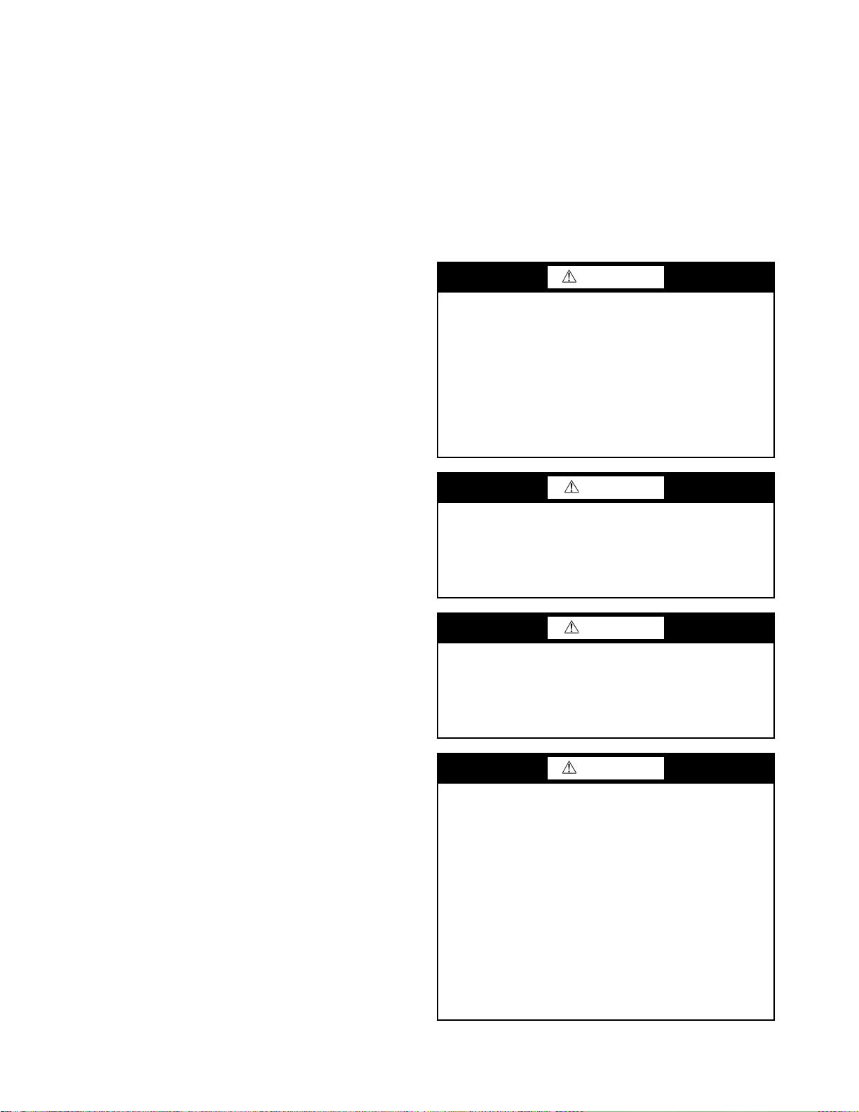
WARNING
Before performing service or maintenance operation on
unit turn off and lock off main power switch to unit.
Electrical shock can cause personal injury and death.
Shut off all power to this equipment during installation
and service. The unit may have an internal non-fused
disconnect or a field-installed disconnect. Note that the
unit may also be equipped with a convenience outlet,
that this outlet is wired to the line side of the unitmounted disconnect and will remain hot when the
disconnect in the unit is off. There is a separate fuse/
disconnect for the convenience outlet.
CAUTION
Puron® refrigerant (R-410A) systems operate at higher
pressures than standard R-22 systems. Do not use R-22 service equipment or components on Puron refrigerant equipment. If service equipment is not rated for Puron
refrigerant, equipment damage or personal injury may
result.
CAUTION
This unit uses a microprocessor-based electronic control
system. Do not use jumpers or other tools to short out com-
ponents or to bypass or otherwise depart from recommended procedures. Any short-to-ground of the control
board or accompanying wiring may destroy the electronic
modules or electrical components.
WARNING
1. Improper installation, adjustment, alteration, service,
or maintenance can cause property damage, personal
injury, or loss of life. Refer to the User’s Information
Manual provided with this unit for more details.
2. Do not store or use gasoline or other flammable vapors and liquids in the vicinity of this or any other
appliance.
What to do if you smell gas:
1. DO NOT try to light any appliance.
2. DO NOT touch any electrical switch, or use any phone
in your building.
3. IMMEDIATELY call your gas supplier from a neighbor’s phone. Follow the gas supplier’s instructions.
4. If you cannot reach your gas supplier call the fire
department.
2
GENERAL
ENTER
ESCAPE
ENTER
This book contains Start-Up, Controls Operation, Troubleshooting and Service information for the 48/50A Series
rooftop units. See Table 1. These units are equipped with
ComfortLink™ controls.
Use this guide in conjunction with the separate installation
instructions packaged with the unit. Refer to the Wiring Diagrams literature for more detailed wiring information.
Table 1 — A Series Product Line
UNIT APPLICATION
48AJ CV Unit with Gas Heat, Vertical Supply
48AK VAV Units with Gas Heat, Vertical Supply
48AW CV Unit with Gas Heat, Horizontal Supply
48AY VAV Unit with Gas Heat, Horizontal Supply
48A2 CV Unit with Gas Heat, Vertical Supply with MCHX Coil
48A3 VAV Unit with Gas Heat, Vertical Supply with MCHX Coil
48A4 CV Unit with Gas Heat, Horizontal Supply with MCHX Coil
48A5 VAV Unit with Gas Heat, Horizontal Supply with MCHX Coil
50AJ CV Unit with Optional Electric Heat, Vertical Supply
50AK VAV Unit with Optional Electric Heat, Vertical Supply
50AW CV Unit with Optional Electric Heat, Horizontal Supply
50AY VAV Unit with Optional Electric Heat, Horizontal Supply
CV Unit with Optional Electric Heat, Vertical Supply with MCHX
50A2
Coil
VAV Unit with Optional Electric Heat, Vertical Supply with MCHX
50A3
Coil
CV Unit with Optional Electric Heat, Horizontal Supply with
50A4
MCHX Coil
VAV Unit with Optional Electric Heat, Horizontal Supply with
50A5
MCHX Coil
LEGEND
CV — Constant Volume
MCHX — Microchannel Heat Exchanger
VAV — Varia bl e Ai r Vol ume
The A Series units provide ventilation, cooling, and heating
(when equipped) in variable air volume (VAV), variable volume
and temperature (VVT®), and constant volume (CV) applications. The A Series units contain the factory-installed Com-
fortLink™ control system which provides full system management. The main base board (MBB) stores hundreds of unit configuration settings and 8 time of day schedules. The MBB also
performs self diagnostic tests at unit start-up, monitors the operation of the unit, and provides alarms and alert information. The
system also contains other optional boards that are connected to
the MBB through the Local Equipment Network (LEN). Information on system operation and status are sent to the MBB processor by various sensors and optional boards that are located at
the unit. Access to the unit controls for configuration, set point
selection, schedule creation, and service can be done through a
unit-mounted scrolling marquee. Access can also be done
through the Carrier Comfort Network
ComfortVIEW™ software, the accessory Navigator™ handheld display, or the System Pilot™ interface.
The ComfortLink system controls all aspects of the rooftop.
It controls the supply-fan motor, compressors, and economizers to maintain the proper temperature conditions. The controls
also cycle condenser fans to maintain suitable head pressure.
All VAV units are equipped with a standard VFD (variable frequency drive) for supply fan speed control and supply duct
pressure control. The ComfortLink controls adjust the speed of
the VFD based on a static pressure sensor input. In addition,
the ComfortLink controls can raise or lower the building pressure using multiple power exhaust fans controlled from economizer damper position or from a building pressure sensor. The
control safeties are continuously monitored to ensure safe operation under all conditions. Sensors include suction pressure
transducers, discharge pressure transducers, and saturated condensing temperature sensors which allow for display of operational pressures and saturation temperatures.
®
(CCN) system using the
A scheduling function, programmed by the user, controls
the unit occupied/unoccupied schedule. Up to 8 different
schedules can be programmed.
The controls also allow the service person to operate a quick
test so that all the controlled components can be checked for
proper operation.
Conventions Used in This Manual — The follow-
ing conventions for discussing configuration points for the local display (scrolling marquee or Navigator accessory) will be
used in this manual.
Point names will be written with the Mode name first, then
any sub-modes, then the point name, each separated by an
arrow symbol (). Names will also be shown in bold and
italics. As an example, the IAQ Economizer Override Position
which is located in the Configuration mode, Indoor Air Quality
Configuration sub-mode, and the Air Quality Set Points
sub-sub-mode, would be written as Configuration
IAQIAQ.SPIQ.O.P. A list of point names can be found in
Appendix A.
This path name will show the user how to navigate through
the local display to reach the desired configuration. The user
would scroll through the modes and submodes using the
and keys. The arrow symbol in the path name represents pressing to move into the next level of the
menu structure.
When a value is included as part of the path name, it will be
shown at the end of the path name after an equals sign. If the
value represents a configuration setting, an explanation will be
shown in parentheses after the value. As an example, Configu-
ration
IAQAQ.CFIQ.AC = 1 (IAQ Analog Input).
Pressing the and keys simultaneously
at any time will display an expanded text description of the fourcharacter point name. The expanded description is shown in the
local display tables (Appendix A).
The CCN point names are also referenced in the local
display tables for users configuring the unit with CCN software
instead of the local display. The CCN tables are located in
Appendix B of this manual.
BASIC CONTROL USAGE
ComfortLink Controls —
system is a comprehensive unit-management system. The control system is easy to access, configure, diagnose and troubleshoot.
The control is flexible, providing two types of constant
volume cooling control sequences, two variable air volume
cooling control sequences, and heating control sequences for
two-stage electric and gas systems, and for multiple-stage gas
heating, in both Occupied and Unoccupied schedule modes.
This control also manages:
• VAV duct pressure (through optional VFD), with reset
• Building pressure through two different power exhaust
schemes
• Condenser fan cycling for mild ambient head pressure
control
• Space ventilation control, in Occupied and Unoccupied
periods, using CO
tilation defined by damper position
• Smoke control functions
• Occupancy schedules
• Occupancy or start/stop sequences based on third party
signals
• Alarm status and history and run time data
• Management of a complete unit service test sequence
sensors or external signals, with ven-
2
The ComfortLink control
3
System diagnostics are enhanced by the use of multiple
ESCAPE
ENTER
ESCAPE
ENTER
ENTER
ESCAPE
Run Status
Service Test
Temperature
Pressures
Setpoints
Inputs
Outputs
Configuration
Time Clock
Operating Modes
Alarms
Alarm Status
ENTER
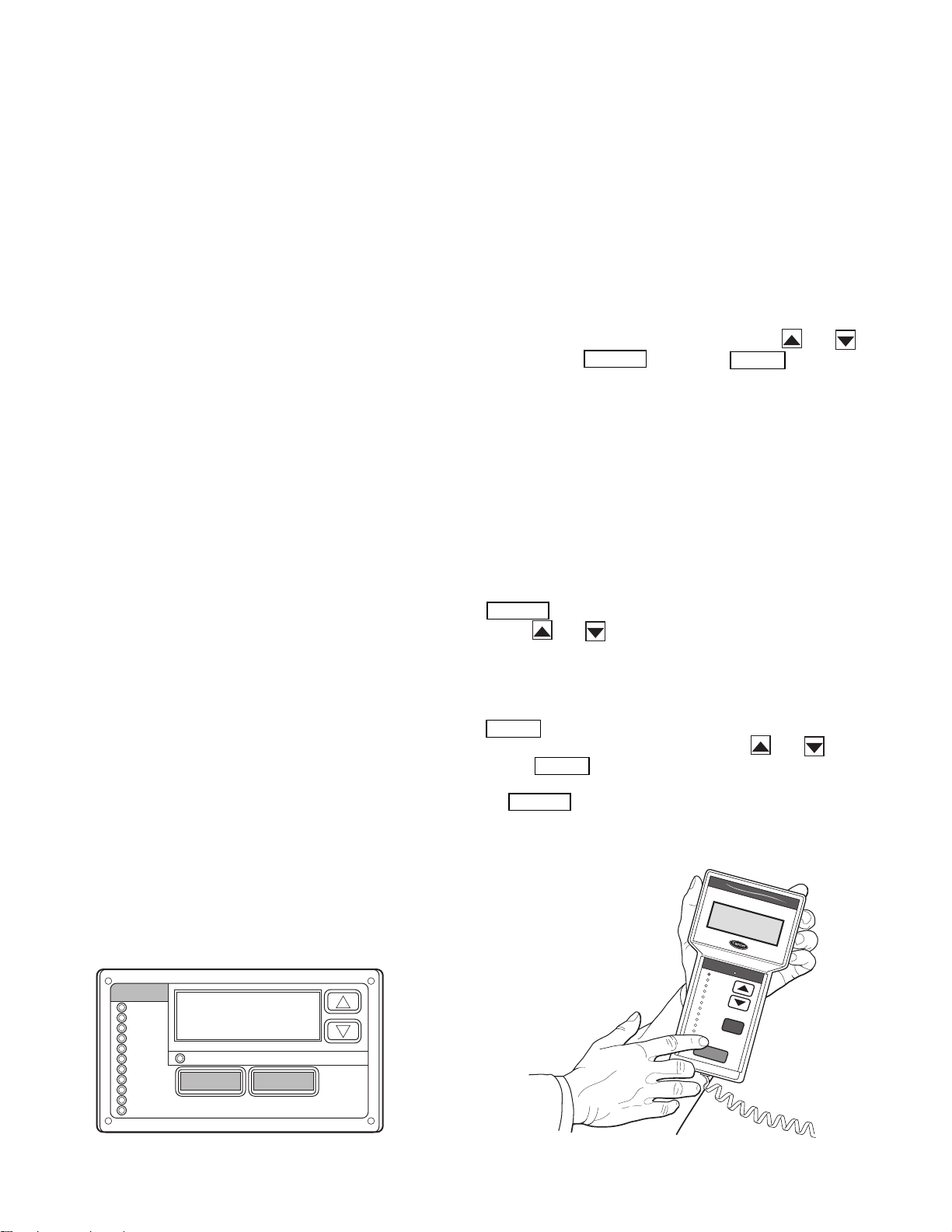
MODE
ESCAPE
Fig. 1 — Scrolling Marquee
A30-2239
Ru
n Sta
tu
s
S
e
rv
ice
Te
s
t
T
em
p
era
ture
s
P
res
s
ure
s
S
e
tpo
in
ts
In
pu
ts
O
utp
uts
C
on
fig
u
ra
tion
T
im
e
Clo
ck
O
p
er
ating
M
od
es
A
la
rm
s
E
N
T
E
R
E
S
C
M
O
D
E
Ala
rm
Sta
tus
T
IM
E
E
W
T
L
W
T
S
E
T
P
1
2
.
5
8
5
4
.
6
F
4
4
.1
F
4
4
.
0
F
N
A
V
I
G
A
T
O
R
C
o
m
f
o
r
t
L
in
k
Fig. 2 — Accessory Navigator Display
30-650
external sensors for air temperatures, air pressures, refrigerant
temperatures, and refrigerant pressures. Unit-mounted actuators provide digital feedback data to the unit control.
The ComfortLink control system is fully communicating
and cable-ready for connection to the Carrier Comfort Net-
®
work
(CCN) building management system. The control provides high-speed communications for remote monitoring via
the Internet. Multiple units can be linked together (and to other
ComfortLink control equipped units) using a 3-wire communication bus.
The ComfortLink control system is easy to access through
the use of a unit-mounted display module. There is no need to
bring a separate computer to this unit for start-up. Access to
control menus is simplified by the ability to quickly select from
11 menus. A scrolling readout provides detailed explanations
of control information. Only four, large, easy-to-use buttons are
required to maneuver through the entire controls menu.
For added service flexibility, an accessory hand-held
Navigator module is also available. This portable device has an
extended communication cable that can be plugged into the
unit’s communication network either at the main control box or
at the opposite end of the unit, at a remote modular plug. The
Navigator display provides the same menu structure, control
access and display data as is available at the unit-mounted
scrolling marquee display.
Scrolling Marquee — This device is the standard inter-
face used to access the control information, read sensor values,
and test the unit. The scrolling marquee is located in the main
control box. The scrolling marquee display is a 4-key, 4-character LED (light-emitting diode) display module. The display
also contains an Alarm Status LED. See Fig. 1. The display is
easy to operate using 4 buttons and a group of 11 LEDs that indicate the following menu structures, referred to as modes (see
Appendix A):
• Run Status
• Service Test
• Temperatures
•Pressures
• Set points
• Inputs
• Outputs
• Configuration
• Timeclock
• Operating Modes
•Alarms
Through the scrolling marquee, the user can access all of the
inputs and outputs to check on their values and status, configure operating parameters plus evaluate the current decision status for operating modes. Because the A Series units are
equipped with suction pressure and saturated condensing
temperature transducers, the scrolling marquee can also display
refrigerant circuit pressures typically obtained from service
gages. The control also includes an alarm history which can be
accessed from the display. In addition, through the scrolling
marquee, the user can access a built-in test routine that can be
used at start-up commissioning to diagnose operational problems with the unit.
Accessory Navigator™ Display — The accessory
hand-held Navigator display can be used with the A Series
units. See Fig. 2. The Navigator display operates the same way
as the scrolling marquee device. The Navigator display is
plugged into the RJ-14 (LEN) jack in the main control box on
the COMM board. The Navigator display can also be plugged
into the RJ-14 jack located on the ECB (economizer control
board) located in the auxiliary control box.
Operation — All units are shipped from the factory with
the scrolling marquee display, which is located in the main control box. See Fig. 1. In addition, the ComfortLink™ controls
also support the use of the handheld Navigator display.
Both displays provide the user with an interface to the
ComfortLink control system. The displays have and
arrow keys, an key and an key. These
keys are used to navigate through the different modes of the
display structure. The Navigator and the scrolling marquee displays operate in the same manner, except that the Navigator
display has multiple lines of display and the scrolling marquee
has a single line. All further discussions and examples in this
document will be based on the scrolling marquee display. See
Table 2 for the menu structure.
The four keys are used to navigate through the display
structure, which is organized in a tiered mode structure. If the
buttons have not been used for a period, the display will default
to the AUTO VIEW display category as shown under the RUN
STATUS category. To show the top-level display, press the
key until a blank display is shown. Then
use the and arrow keys to scroll through the top-level
categories (modes). These are listed in Appendix A and will be
indicated on the scrolling marquee by the LED next to each
mode listed on the face of the display.
When a specific mode or sub-mode is located, push the
key to enter the mode. Depending on the mode, there
may be additional tiers. Continue to use the and keys
and the keys until the desired display item is found.
At any time, the user can move back a mode level by pressing
the key. Once an item has been selected the display
will flash showing the item, followed by the item value and
then followed by the item units (if any).
4
ENTER
ESCAPE
ENTER
ESCAPE
ENTER
ENTER
ENTER
ENTER
ESCAPE
ENTER
SCROLL
+
-
NAVIGATE/
EXIT
MODIFY/
SELECT
PAGE
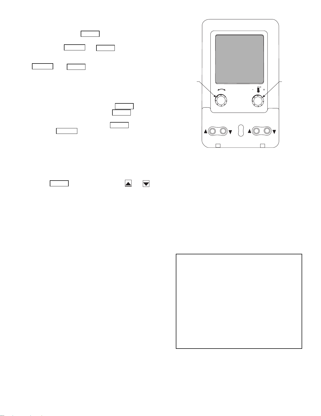
Fig. 3 — System Pilot™ User Interface
A33-1050
Items in the Configuration and Service Test modes are
password protected. The display will flash PASS and WORD
when required. Use the and arrow keys to enter the
four digits of the password. The default password is 1111.
Pressing the and keys simultaneously
will scroll an expanded text description across the display indicating the full meaning of each display point. Pressing the
and keys when the display is blank
(MODE LED level) will return the display to its default menu
of rotating AUTO VIEW display items. In addition, the password will need to be entered again before changes can be made.
Changing item values or testing outputs is accomplished in
the same manner. Locate and display the desired item. If the
display is in rotating auto-view, press the key to stop
the display at the desired item. Press the key again so
that the item value flashes. Use the arrow keys to change the
value of state of an item and press the key to accept
it. Press the key and the item, value or units display
will resume. Repeat the process as required for other items.
If the user needs to force a variable, follow the same process
as when editing a configuration parameter. A forced variable
will be displayed with a blinking “f” following its value. For
example, if supply fan requested (FA N. F) is forced, the display
shows “YESf”, where the “f” is blinking to signify a force on
the point. Remove the force by selecting the point that is forced
with the key and then pressing the and arrow keys simultaneously.
Depending on the unit model, factory-installed options and
field-installed accessories, some of the items in the various
Mode categories may not apply.
System Pilot™ Interface — The System Pilot
(33PILOT-01) device is a component of Carrier’s 3V™ system
and serves as a user-interface and configuration tool for all Carrier communicating devices. The System Pilot device can be
used to install and commission a 3V zoning system, linkage
compatible air source, universal controller, and all other devices operating on the CCN system.
Additionally, the System Pilot device can serve as a
wall-mounted temperature sensor for space temperature
measurement. The occupant can use the System Pilot device to
change set points. A security feature is provided to limit access
of features for unauthorized users. See Fig. 3 for System Pilot
details.
CCN Tables and Display — In addition to the unit-
mounted scrolling marquee display, the user can also access the
same information through the CCN tables by using the Service
Tool or other CCN programs. Details on the CCN tables are
summarized in Appendix B. The variable names used for the
CCN tables and the scrolling marquee tables may be different
and more items are displayed in the CCN tables. As a reference, the CCN variable names are included in the scrolling
marquee tables and the scrolling marquee names are included
in the local display tables in Appendix B.
GENERICS STATUS DISPLAY TABLE — The GENERICS
points table allows the service/installer the ability to create a
custom table in which up to 20 points from the 5 CCN
categories (Points, Config, Service-Config, Set Point, and
Maintenance) may be collected and displayed.
In the Service-Config table section, there is a table named
“generics”. This table contains placeholders for up to 20 CCN
point names and allows the user to decide which points are displayed in the GENERICS points table under the local display.
Each one of these placeholders allows the input of an 8-character
ASCII string. Using a CCN interface, enter the Edit mode for the
Service-Config table “generics” and enter the CCN name for
each point to be displayed in the custom points table in the order
they will be displayed. When done entering point names, download the table to the rooftop unit control.
IMPORTANT: The computer system software
(ComfortVIEW™, Service Tool, etc.) that is used to
interact with CCN controls always saves a template of
items it considers as static (e.g., limits, units, forcibil-
ity, 24-character text strings, and point names) after
the software uploads the tables from a control. There-
after, the software is only concerned with run time
data like value and hardware/force status. With this in
mind, it is important that anytime a change is made to
the Service-Config table “generics” (which in turn
changes the points contained in the GENERICS point
table), that a complete new upload be performed. This
requires that any previous table database be
completely removed first. Failure to do this will not
allow the user to display the new points that have been
created and the CCN interface will have a different
table database than the unit control.
5
RUN
STATUS
Auto View of
Run Status
(VIEW)
Econ
Run Status
(ECON)
Cooling
Information
(COOL)
Mode
Trip Helper
(TRIP)
CCN
Linkage
(LINK)
Compressor
Run Hours
(HRS)
Compressor
Starts
(STRT)
Timeguards
(TMGD)
Software
Ver sio n
Numbers
(VERS)
SERVICE
TEST
Service Test Mode
(TEST)
Software
Command
Disable
(STOP)
Soft Stop
Request
(S.STP)
Supply Fan
Request
(FAN.F)
4 in. Filter
Change Mode
(F.4.CH)
Test Independent
Outputs
(INDP)
Te st F an s
(FANS)
Test Cooling
(COOL)
Test Heating
(HEAT)
Table 2 — Scrolling Marquee Menu Display Structure
(ComfortLink™ Display Modes)
TEMPERATURES PRESSURES SETPOINTS INPUTS OUTPUTS CONFIGURATION
Air
Temperatures
(AIR.T)
Refrigerant
Temperatures
(REF.T)
Air Pressures
(AIR.P)
Refrigerant
Pressures
(REF.P)
Occupied Heat
Setpoint
(OHSP)
Occupied Cool
Setpoint
(OCSP)
Unoccupied
Heat Setpoint
(UHSP)
Unoccupied
Cool Setpoint
(UCSP)
Heat - Cool
Setpoint
(GAP)
VAV O cc
Cool On
(V.C.ON)
VAV O cc
Cool Off
(V.C.OF)
Supply Air
Setpoint
(SASP)
Supply Air
Setpoint Hi
(SA.HI)
General Inputs
(GEN.I)
Compressor
Feedback
(FD.BK)
Thermostat
Inputs
(STAT)
Fire-Smoke
Modes
(FIRE)
Relative
Humidity
(REL.H)
Air Quality
Sensors
(AIR.Q)
Reset Inputs
(RSET)
4-20 Milliamp
Inputs
(4-20)
Fans
(FANS)
Cooling
(COOL)
Heating
(HEAT)
Economizer
(ECON)
General
Outputs
(GEN.O)
Unit
Configuration
(UNIT)
Cooling
Configuration
(COOL)
Evap/Discharge
Temp. Reset
(EDT.R)
Heating
Configuration
(HEAT)
Supply Static
Press. Config.
(SP)
Economizer
Configuration
(ECON)
Building Press.
Configs
(BP)
Cool/Heat
Setpt. Offsets
(D.LV.T)
Demand Limit
Config.
(DMD.L)
TIME
CLOCK
Time of Day
(TIME)
Month, Date,
Day and Year
(DATE)
Local Time
Schedule
(SCH.L)
Local
Holiday
Schedules
(HOL.L)
Daylight
Savings
Time
(DAY.S)
OPERATING
MODES
System
Mode
(SYS.M)
HVAC Mode
(HVAC)
Control Type
(CTRL)
Mode
Controlling
Unit
(MODE)
ALARMS
Currently
Active
Alarms
(CURR)
Reset All
Current
Alarms
(R.CUR)
Alarm
History
(HIST)
Supply Air
Setpoint Lo
(SA.LO)
Heating Supply
Air Setpoint
(SA.HT)
Te mp e r i ng
Purge SASP
(T.PRG)
Tempering in
Cool SASP
(T.CL)
Tempering in
Vent Occ SASP
(T.V.OC)
Tempering in
Vent Unocc.
SASP
(T.V.UN)
Indoor Air
Quality Cfg.
(IAQ)
Dehumidification
Config.
(DEHU)
CCN
Configuration
(CCN)
Alert Limit
Config.
(ALLM)
Sensor Trim
Config.
(TRIM)
Switch
Logic
(SW.LG)
Display
Configuration
(DISP)
6

START-UP
Controls — Use the following steps for the controls:
IMPORTANT: Do not attempt to start unit, even
momentarily, until all items on the Start-Up Checklist
and the following steps have been completed.
Unit Preparation —
accordance with the installation instructions and applicable
codes.
Check that unit has been installed in
Unit Setup — Make sure that the economizer hoods have
been installed and that the outdoor filters are properly installed.
Internal Wiring — Ensure that all electrical connections
in the control box are tightened as required. If the unit has
staged gas heat make sure that the leaving air temperature
(LAT) sensors have been routed to the supply ducts as required.
Accessory Installation — Check to make sure that all
accessories including space thermostats and sensors have been
installed and wired as required by the instructions and unit
wiring diagrams.
Crankcase Heaters — Crankcase heaters are energized
as long as there is power to the unit, except when the compressors are running.
IMPORTANT: Unit power must be on for 24 hrs prior
to start-up of compressors. Otherwise damage to compressors may result.
Evaporator Fan — Fan belt and fixed pulleys are factory-
installed. See Tables 3-38 for fan performance. Remove tape
from fan pulley, and be sure that fans rotate in the proper direction. See Table 39 for motor limitations. See Tables 40A and
40B for air quantity limits. Static pressure drop for power
exhaust is negligible. To alter fan performance, see Evaporator
Fan Performance Adjustment section on page 130.
IMPORTANT: The unit is shipped with the unit control
disabled. To enable the control, set Local Machine Disable
(Service Test
1. Set any control configurations that are required (fieldinstalled accessories, etc.). The unit is factory configured
for all appropriate factory-installed options.
2. Enter unit set points. The unit is shipped with the set point
default values. If a different set point is required use the
scrolling marquee, Navigator™ accessory or Service
Tool software to change the configuration valves.
3. If the internal unit schedules are going to be used configure the Occupancy schedule.
4. Verify that the control time periods programmed meet
current requirements.
5. Using Service Test mode, verify operation of all major
components.
6. If the unit is a VAV unit make sure to configure the VFD
static pressure set point using the display. To checkout the
VFD use the VFD instructions shipped with the unit.
STOP) to No.
Gas Heat — Verify gas pressure before turning on gas heat
as follows:
1. Turn off field-supplied manual gas stop, located external
to the unit.
2. Connect pressure gages to supply gas tap, located at fieldsupplied manual shutoff valves.
3. Connect pressure gages to manifold pressure tap on unit
gas valve.
4. Supply gas pressure must not exceed 13.5 in. wg. Check
pressure at field-supplied shut-off valve.
5. Turn on manual gas stop and initiate a heating demand.
Jumper R to W1 in the control box to initiate heat.
6. Use the Service Test procedure to verify heat operation.
7. After the unit has run for several minutes, verify that
incoming pressure is 6.0 in. wg or greater and that the
manifold pressure is 3.5 in wg. If manifold pressure must
be adjusted refer to Gas Valve Adjustment section.
7
Table 3 — Fan Performance — 48AJ,AK020,025 and 48A2,A3020 Units
AIRFLOW
(CFM)
4,000 328 0.62 406 0.84 472 1.07 529 1.30 580 1.54 626 1.78 668 2.02 708 2.27 745 2.51 780 2.76
5,000 369 0.97 439 1.19 500 1.43 554 1.69 604 1.95 650 2.21 692 2.48 731 2.74 769 3.01 804 3.28
6,000 415 1.43 477 1.65 533 1.90 584 2.17 631 2.45 676 2.73 717 3.01 756 3.30 793 3.59 828 3.88
7,000 463 2.01 519 2.25 570 2.50 618 2.78 662 3.06 704 3.36 744 3.65 782 3.96 818 4.27 852 4.58
7,500 488 2.36 541 2.60 590 2.86 636 3.13 679 3.42 720 3.72 759 4.02 796 4.33 832 4.65 866 4.96
8,000 513 2.74 564 2.98 611 3.24 655 3.52 697 3.81 737 4.11 775 4.42 811 4.74 846 5.06 879 5.38
9,000 564 3.61 612 3.87 655 4.13 696 4.42 735 4.71 772 5.02 808 5.33 843 5.65 876 5.98 909 6.32
10,000 616 4.64 661 4.91 701 5.18 739 5.47 776 5.77 811 6.08 845 6.40 878 6.72 909 7.06 940 7.40
11,000 669 5.84 711 6.11 749 6.40 785 6.69 819 6.99 852 7.30 884 7.63 915 7.96 945 8.30 975 8.65
12,000 723 7.20 762 7.49 798 7.78 831 8.08 864 8.39 895 8.71 925 9.04 955 9.37 984 9.72 1012 10.07
12,500 750 7.95 788 8.25 823 8.54 855 8.85 887 9.16 917 9.48 947 9.81 976 10.15 1004 10.49 1031 10.84
13,000 777 8.75 814 9.05 848 9.35 880 9.66 910 9.97 940 10.30 969 10.63 997 10.97 1024 11.31 1051 11.67
0.2 0.4 0.6 0.8 1.0 1.2 1.4 1.6 1.8 2.0
Rpm Bhp Rpm Bhp Rpm Bhp Rpm Bhp Rpm Bhp Rpm Bhp Rpm Bhp Rpm Bhp Rpm Bhp Rpm Bhp
AVAILABLE EXTERNAL STATIC PRESSURE (in. wg)
AIRFLOW
(CFM)
4,000 814 3.01 845 3.26 876 3.51 905 3.76 934 4.02 961 4.28 987 4.54 1013 4.80 1038 5.06 1062 5.32
5,000 837 3.55 869 3.82 900 4.10 929 4.37 958 4.64 985 4.92 1012 5.20 1038 5.48 1063 5.76 1087 6.04
6,000 861 4.17 893 4.46 923 4.76 953 5.05 981 5.35 1009 5.65 1036 5.94 1062 6.24 1087 6.54 1111 6.84
7,000 885 4.89 917 5.20 947 5.51 977 5.83 1005 6.14 1033 6.46 1059 6.78 1085 7.09 1110 7.41 1135 7.73
7,500 898 5.28 930 5.61 960 5.93 989 6.25 1017 6.58 1045 6.90 1071 7.23 1097 7.56 1122 7.88 1147 8.21
8,000 912 5.71 943 6.04 973 6.37 1002 6.70 1030 7.04 1057 7.37 1083 7.71 1109 8.04 1134 8.38 1159 8.72
9,000 940 6.66 970 7.00 999 7.35 1028 7.69 1055 8.04 1082 8.39 1109 8.75 1134 9.10 1159 9.45 1183 9.81
10,000 971 7.75 1000 8.10 1028 8.46 1056 8.82 1083 9.18 1109 9.54 1135 9.91 1160 10.28 1185 10.65 — —
11,000 1004 9.00 1032 9.36 1059 9.73 1086 10.09 1112 10.46 1138 10.84 1163 11.22 1188 11.60 — — — —
12,000 1039 10.42 1066 10.79 1093 11.16 1119 11.53 1144 11.91 1169 12.30 1193 12.68 — — — — — —
12,500 1058 11.20 1085 11.57 1110 11.94 1136 12.32 1161 12.70 1185 13.09 — — — — — — — —
13,000 1077 12.03 1103 12.40 1129 12.77 1154 13.15 1178 13.54 — — — — — — — — — —
2.2 2.4 2.6 2.8 3.0 3.2 3.4 3.6 3.8 4.0
Rpm Bhp Rpm Bhp Rpm Bhp Rpm Bhp Rpm Bhp Rpm Bhp Rpm Bhp Rpm Bhp Rpm Bhp Rpm Bhp
AVAILABLE EXTERNAL STATIC PRESSURE (in. wg)
Table 4 — Fan Performance — 48AJ,AK027,030 and 48A2,A3025-030 Units
AIRFLOW
(CFM)
4,000 331 0.63 408 0.85 474 1.08 531 1.31 581 1.55 627 1.79 670 2.03 709 2.28 746 2.52 781 2.77
5,000 374 0.98 443 1.20 503 1.45 558 1.70 607 1.96 653 2.23 695 2.49 734 2.76 771 3.03 806 3.30
6,000 421 1.45 482 1.68 538 1.93 589 2.20 636 2.47 680 2.75 721 3.04 759 3.33 796 3.62 831 3.91
7,000 471 2.04 526 2.28 576 2.54 623 2.81 668 3.10 710 3.39 749 3.69 787 4.00 823 4.31 857 4.62
8,000 522 2.78 572 3.03 619 3.29 662 3.57 704 3.86 743 4.16 781 4.47 817 4.79 851 5.11 885 5.44
9,000 574 3.66 621 3.92 664 4.19 704 4.47 743 4.77 780 5.08 815 5.40 850 5.72 883 6.05 915 6.39
10,000 628 4.71 671 4.97 711 5.25 748 5.54 784 5.84 819 6.15 853 6.47 885 6.81 917 7.14 948 7.49
11,000 682 5.91 722 6.19 759 6.48 795 6.77 828 7.08 861 7.40 893 7.72 924 8.06 954 8.40 983 8.75
12,000 736 7.30 774 7.59 809 7.88 842 8.18 874 8.49 905 8.82 935 9.15 965 9.48 993 9.83 1021 10.19
13,000 791 8.86 827 9.16 860 9.46 891 9.78 922 10.09 951 10.42 979 10.75 1007 11.10 1034 11.45 1061 11.80
14,000 846 10.61 880 10.93 912 11.24 941 11.56 970 11.88 998 12.21 1025 12.56 1052 12.90 1078 13.26 1103 13.62
15,000 902 12.56 934 12.89 964 13.21 992 13.54 1020 13.87 1046 14.21 1072 14.55 1098 14.91 1122 15.26 1147 15.63
AIRFLOW
(CFM)
4,000 815 3.02 847 3.27 877 3.52 906 3.77 935 4.03 962 4.29 988 4.55 1014 4.81 1039 5.07 1063 5.33
5,000 839 3.57 871 3.84 902 4.11 931 4.39 960 4.66 987 4.94 1014 5.22 1039 5.50 1064 5.78 1089 6.06
6,000 864 4.20 896 4.49 926 4.79 956 5.08 984 5.38 1012 5.68 1038 5.97 1064 6.27 1089 6.57 1114 6.87
7,000 890 4.93 921 5.24 951 5.55 980 5.87 1009 6.18 1036 6.50 1063 6.82 1088 7.14 1114 7.45 1138 7.77
8,000 917 5.76 948 6.09 977 6.42 1006 6.76 1034 7.09 1061 7.43 1088 7.76 1113 8.10 1138 8.43 1163 8.77
9,000 946 6.73 976 7.07 1005 7.42 1033 7.76 1061 8.11 1088 8.46 1114 8.82 1139 9.17 1164 9.52 1188 9.88
10,000 978 7.84 1007 8.19 1035 8.55 1063 8.91 1089 9.27 1116 9.63 1141 10.00 1166 10.37 1191 10.74 — —
11,000 1012 9.10 1040 9.47 1067 9.83 1094 10.20 1120 10.57 1145 10.95 1170 11.33 1195 11.71 — — — —
12,000 1048 10.54 1075 10.91 1102 11.28 1127 11.66 1152 12.04 1177 12.42 — — — — — — — —
13,000 1087 12.17 1113 12.54 1138 12.91 1163 13.30 1187 13.68 — — — — — — — — — —
14,000 1128 13.98 1153 14.36 1177 14.74 — — ————————————
15,000 117116.00119416.38————————————————
LEGEND
Bhp — Brake Horsepower
edb — Entering Dry Bulb
ewb — Entering Wet Bulb
NOTES:
1. Fan performance is based on wet coils, economizer, roof curb, cabinet
losses, and clean 2-in. filters.
0.2 0.4 0.6 0.8 1.0 1.2 1.4 1.6 1.8 2.0
Rpm Bhp Rpm Bhp Rpm Bhp Rpm Bhp Rpm Bhp Rpm Bhp Rpm Bhp Rpm Bhp Rpm Bhp Rpm Bhp
2.2 2.4 2.6 2.8 3.0 3.2 3.4 3.6 3.8 4.0
Rpm Bhp Rpm Bhp Rpm Bhp Rpm Bhp Rpm Bhp Rpm Bhp Rpm Bhp Rpm Bhp Rpm Bhp Rpm Bhp
AVAILABLE EXTERNAL STATIC PRESSURE (in. wg)
AVAILABLE EXTERNAL STATIC PRESSURE (in. wg)
2. Conversion — Bhp to watts:
Watts =
3. Variable air volume units will operate down to 70 cfm/ton. Performance at
70 cfm/ton is limited to unloaded operation and may be additionally limited
by edb and ewb conditions.
Bhp x 746
Motor efficiency
8
Table 5 — Fan Performance — 48AJ,AK,A2,A3035 Units
AIRFLOW
(Cfm)
7,000 534 2.46 584 2.80 630 3.13 674 3.48 716 3.82 756 4.16 793 4.50 829 4.83 863 5.17 896 5.49
8,000 590 3.27 635 3.63 677 3.99 718 4.35 757 4.72 794 5.08 830 5.45 864 5.81 897 6.18 929 6.54
9,000 646 4.23 687 4.62 726 5.00 764 5.38 800 5.76 835 6.15 869 6.54 902 6.93 934 7.31 964 7.70
10,000 704 5.35 742 5.77 778 6.17 812 6.57 846 6.97 879 7.38 911 7.78 942 8.19 972 8.60 1002 9.01
10,500 733 5.97 769 6.40 804 6.82 837 7.23 870 7.64 902 8.05 933 8.46 963 8.88 992 9.30 1021 9.72
11,000 762 6.63 797 7.08 830 7.51 863 7.93 894 8.35 925 8.77 955 9.19 984 9.62 1013 10.04 1041 10.47
12,000 820 8.09 853 8.56 884 9.01 915 9.46 944 9.90 973 10.34 1001 10.78 1029 11.22 1056 11.66 1083 12.10
13,000 879 9.72 909 10.22 939 10.70 968 11.17 996 11.63 1023 12.09 1050 12.55 1076 13.01 1102 13.46 1127 13.92
14,000 938 11.54 967 12.07 995 12.58 1022 13.07 1048 13.55 1074 14.03 1099 14.51 1124 14.98 1149 15.46 1173 15.93
15,000 997 13.56 1024 14.11 1051 14.64 1076 15.16 1102 15.67 1126 16.17 1150 16.66 1174 17.16 1197 17.65 1220 18.14
16,000 1056 15.78 1082 16.35 1107 16.91 1132 17.45 1156 17.98 1179 18.50 1202 19.02 1225 19.53 1247 20.04 1269 20.55
17,000 1116 18.20 1140 18.80 1164 19.38 1188 19.95 1210 20.50 1233 21.05 1255 21.58 1276 22.11 1298 22.64 — —
17,500 114519.49117020.10119320.70121621.28123821.84126022.40128222.94——————
AIRFLOW
(Cfm)
7,000 927 5.81 956 6.13 985 6.45 1012 6.76 1039 7.06 1065 7.37 1090 7.67 1114 7.97 1138 8.26 1161 8.56
8,000 960 6.89 989 7.25 1018 7.60 1045 7.94 1072 8.29 1098 8.63 1122 8.96 1147 9.29 1170 9.62 1193 9.95
9,000 994 8.09 1023 8.47 1051 8.85 1078 9.23 1104 9.61 1130 9.98 1155 10.35 1179 10.71 1203 11.08 1226 11.44
10,000 1030 9.42 1058 9.82 1085 10.23 1112 10.64 1138 11.04 1163 11.44 1188 11.84 1212 12.24 1235 12.64 1258 13.03
10,500 1049 10.14 1077 10.56 1103 10.97 1129 11.39 1155 11.81 1180 12.23 1204 12.64 1228 13.05 1251 13.46 1274 13.87
11,000 1069 10.90 1095 11.33 1122 11.76 1147 12.18 1173 12.61 1197 13.04 1221 13.47 1245 13.89 1268 14.31 1291 14.73
12,000 110912.55113513.00116013.44118513.89120914.34123314.79125615.24127915.69————
13,000 115214.38117614.84120015.31122415.77124816.24127116.70129317.17——————
14,000 119616.41122016.88124317.36126617.84128818.32——————————
15,000 124318.63126519.12128719.61——————————————
16,000 129021.06——————————————————
17,000 ————————————————————
17,500 ————————————————————
0.20.40.60.81.01.21.41.61.82.0
Rpm Bhp Rpm Bhp Rpm Bhp Rpm Bhp Rpm Bhp Rpm Bhp Rpm Bhp Rpm Bhp Rpm Bhp Rpm Bhp
2.22.42.62.83.03.23.43.63.84.0
Rpm Bhp Rpm Bhp Rpm Bhp Rpm Bhp Rpm Bhp Rpm Bhp Rpm Bhp Rpm Bhp Rpm Bhp Rpm Bhp
AVAILABLE EXTERNAL STATIC PRESSURE (in. wg)
AVAILABLE EXTERNAL STATIC PRESSURE (in. wg)
Table 6 — Fan Performance — 48AJ,AK036 Units
AIRFLOW
(Cfm)
7,000 454 2.15 508 2.52 557 2.90 605 3.29 650 3.69
8,000 502 2.90 550 3.30 596 3.71 639 4.12 680 4.54
9,000 552 3.81 595 4.24 637 4.67 677 5.11 715 5.55
10,000 602 4.89 642 5.34 680 5.80 717 6.26 752 6.73
11,000 653 6.15 689 6.62 725 7.11 759 7.59 792 8.08
12,000 704 7.60 738 8.09 771 8.60 803 9.11 834 9.63
13,000 756 9.24 788 9.76 818 10.29 848 10.83 878 11.36
14,000 808 11.10 838 11.64 867 12.19 895 12.74 922 13.30
15,000 861 13.18 888 13.74 915 14.31 942 14.88 968 15.46
16,000 914 15.49 940 16.06 965 16.65 990 17.24 1015 17.85
17,000 967 18.03 991 18.62 1015 19.23 1039 19.85 1062 20.47
17,500 993 19.40 1017 20.00 1040 20.61 1064 21.24 1086 21.87
AIRFLOW
(Cfm)
7,000 693 4.09 734 4.52 773 4.95 811 5.39 847 5.83
8,000 720 4.97 759 5.40 796 5.85 832 6.31 867 6.77
9,000 752 6.00 788 6.45 823 6.92 857 7.39 890 7.87
10,000 787 7.20 821 7.67 854 8.16 886 8.64 917 9.14
11,000 825 8.58 856 9.07 887 9.57 918 10.08 947 10.59
12,000 865 10.14 895 10.66 924 11.18 952 11.71 980 12.24
13,000 906 11.90 935 12.44 962 12.99 989 13.53 1016 14.08
14,000 950 13.87 976 14.43 1002 15.00 1028 15.57 1053 16.14
15,000 994 16.05 1019 16.63 1044 17.22 1068 17.81 1093 18.40
16,000 1039 18.45 1063 19.06 1087 19.67 1110 20.28 1133 20.89
17,000 1086 21.09 1109 21.72 1131 22.35 1153 22.98 1175 23.61
17,500 1109 22.50 1131 23.14 1154 23.78 1175 24.42 1197 25.07
AIRFLOW
(Cfm)
7,000 881 6.29 914 6.74 946 7.21 977 7.68 1006 8.15
8,000 901 7.24 933 7.72 965 8.20 995 8.69 1024 9.19
9,000 923 8.35 954 8.85 985 9.35 1014 9.86 1043 10.37
10,000 948 9.64 978 10.15 1007 10.66 1036 11.19 1064 11.71
11,000 976 11.11 1005 11.63 1033 12.16 1061 12.70 1088 13.24
12,000 1008 12.77 1035 13.31 1062 13.86 1088 14.41 1114 14.97
13,000 1042 14.64 1068 15.19 1093 15.76 1118 16.32 1143 16.89
14,000 1078 16.71 1103 17.28 1127 17.86 1151 18.45 1174 19.03
15,000 1116 19.00 1140 19.59 1163 20.19 1186 20.79 1208 21.40
16,000 1156 21.51 1178 22.12 1200 22.74 1222 23.36 1244 23.98
17,000 1197 24.25 1218 24.89 1240 25.52 1261 26.17 1281 26.81
17,500 1218 25.71 1239 26.36 1260 27.00 1280 27.66 — —
AIRFLOW
(Cfm)
7,000 1035 8.63 1062 9.11 1089 9.60 1115 10.09 1140 10.58
8,000 1053 9.69 1081 10.19 1108 10.70 1134 11.21 1159 11.73
9,000 1072 10.89 1099 11.41 1126 11.94 1152 12.47 1177 13.00
10,000 1092 12.25 1119 12.78 1145 13.33 1171 13.88 1196 14.43
11,000 1114 13.79 1140 14.34 1166 14.90 1191 15.46 1216 16.03
12,000 1139 15.53 1164 16.09 1189 16.67 1213 17.24 1237 17.83
13,000 1167 17.47 1191 18.05 1215 18.64 1238 19.23 1262 19.82
14,000 1198 19.63 1221 20.22 1244 20.82 1266 21.43 1288 22.04
15,000 1230 22.00 1253 22.62 1274 23.23 1296 23.85 — —
16,000 126524.61128625.24——————
17,000 ——————————
17,500 ——————————
LEGEND
Bhp — Brake Horsepower
edb — Entering Dry Bulb
ewb — Entering Wet Bulb
NOTES:
1. Fan performance is based on wet coils, economizer, roof curb, cabinet losses, and clean
2-in. filters.
0.2 0.4 0.6 0.8 1.0
Rpm Bhp Rpm Bhp Rpm Bhp Rpm Bhp Rpm Bhp
1.2 1.4 1.6 1.8 2.0
Rpm Bhp Rpm Bhp Rpm Bhp Rpm Bhp Rpm Bhp
2.2 2.4 2.6 2.8 3.0
Rpm Bhp Rpm Bhp Rpm Bhp Rpm Bhp Rpm Bhp
3.2 3.4 3.6 3.8 4.0
Rpm Bhp Rpm Bhp Rpm Bhp Rpm Bhp Rpm Bhp
AVAILABLE EXTERNAL STATIC PRESSURE (in. wg)
AVAILABLE EXTERNAL STATIC PRESSURE (in. wg)
AVAILABLE EXTERNAL STATIC PRESSURE (in. wg)
AVAILABLE EXTERNAL STATIC PRESSURE (in. wg)
2. Conversion — Bhp to watts:
Watts =
3. Var iable air volume units will operate down to 70 cfm/ton. Performance at 70 cfm/ton is
limited to unloaded operation and may be additionally limited by edb and ewb conditions.
Bhp x 746
Motor efficiency
9
Table 7 — Fan Performance — 48AJ,AK,A2,A3040 Units
AIRFLOW
(Cfm)
8,000 502 2.90 550 3.30 596 3.71 639 4.12 680 4.54 720 4.97 759 5.40 796 5.85 832 6.31 867 6.77
9,000 552 3.81 595 4.24 637 4.67 677 5.11 715 5.55 752 6.00 788 6.45 823 6.92 857 7.39 890 7.87
10,000 602 4.89 642 5.34 680 5.80 717 6.26 752 6.73 787 7.20 821 7.67 854 8.16 886 8.64 917 9.14
11,000 653 6.15 689 6.62 725 7.11 759 7.59 792 8.08 825 8.58 856 9.07 887 9.57 918 10.08 947 10.59
12,000 704 7.60 738 8.09 771 8.60 803 9.11 834 9.63 865 10.14 895 10.66 924 11.18 952 11.71 980 12.24
13,000 756 9.24 788 9.76 818 10.29 848 10.83 878 11.36 906 1 1.90 935 12.44 962 12.99 989 13.53 1016 14.08
14,000 808 11.10 838 11.64 867 12.19 895 12.74 922 13.30 950 13.87 976 14.43 1002 15.00 1028 15.57 1053 16.14
15,000 861 13.18 888 13.74 915 14.31 942 14.88 968 15.46 994 16.05 1019 16.63 1044 17.22 1068 17.81 1093 18.40
16,000 914 15.49 940 16.06 965 16.65 990 17.24 1015 17.85 1039 18.45 1063 19.06 1087 19.67 1110 20.28 1133 20.89
17,000 967 18.03 991 18.62 1015 19.23 1039 19.85 1062 20.47 1086 21.09 1109 21.72 1131 22.35 1153 22.98 1175 23.61
18,000 1020 20.82 1043 21.43 1066 22.06 1088 22.69 1111 23.33 1133 23.97 1155 24.62 1176 25.27 1197 25.92 1219 26.58
19,000 1073 23.87 1095 24.50 1117 25.14 1138 25.79 1159 26.44 1180 27.11 1201 27.77 1222 28.45 1242 29.12 — —
20,000 112727.18114727.82116828.48118829.15————————————
AIRFLOW
(Cfm)
8,000 901 7.24 933 7.72 965 8.20 995 8.69 1024 9.19 1053 9.69 1081 10.19 1108 10.70 1134 11.21 1159 11.73
9,000 923 8.35 954 8.85 985 9.35 1014 9.86 1043 10.37 1072 10.89 1099 11.41 1126 11.94 1 152 12.47 1177 13.00
10,000 948 9.64 978 10.15 1007 10.66 1036 11.19 1064 11.71 1092 12.25 1119 12.78 1145 13.33 1171 13.88 1196 14.43
11,000 976 11.11 1005 11.63 1033 12.16 1061 12.70 1088 13.24 1114 13.79 1140 14.34 1166 14.90 1191 15.46 1216 16.03
12,000 1008 12.77 1035 13.31 1062 13.86 1088 14.41 1114 14.97 1139 15.53 1164 16.09 1189 16.67 1213 17.24 1237 17.83
13,000 1042 14.64 1068 15.19 1093 15.76 1118 16.32 1143 16.89 1167 17.47 1191 18.05 1215 18.64 1238 19.23 1262 19.82
14,000 1078 16.71 1103 17.28 1127 17.86 1151 18.45 1174 19.03 1198 19.63 1221 20.22 1244 20.82 1266 21.43 1288 22.04
15,000 1116 19.00 1140 19.59 1163 20.19 1186 20.79 1208 21.40 1230 22.00 1253 22.62 1274 23.23 1296 23.85 — —
16,000 115621.51117822.12120022.74122223.36124423.98126524.61128625.24——————
17,000 119724.25121824.89124025.52126126.17128126.81——————————
18,000 123927.24126027.89128028.55——————————————
19,000 ————————————————————
20,000 ————————————————————
0.20.40.60.81.01.21.41.61.82.0
RpmBhpRpmBhpRpmBhpRpmBhpRpmBhpRpmBhpRpmBhpRpmBhpRpmBhpRpmBhp
2.22.42.62.83.03.23.43.63.84.0
RpmBhpRpmBhpRpmBhpRpmBhpRpmBhpRpmBhpRpmBhpRpmBhpRpmBhpRpmBhp
AVAILABLE EXTERNAL STATIC PRESSURE (in. wg)
AVAILABLE EXTERNAL STATIC PRESSURE (in. wg)
Table 8 — Fan Performance — 48AJ,AK041 Units
AIRFLOW
(Cfm)
8,000 502 2.90 550 3.30 596 3.71 639 4.12 680 4.54
9,000 552 3.81 595 4.24 637 4.67 677 5.11 715 5.55
10,000 602 4.89 642 5.34 680 5.80 717 6.26 752 6.73
11,000 653 6.15 689 6.62 725 7.11 759 7.59 792 8.08
12,000 704 7.60 738 8.09 771 8.60 803 9.11 834 9.63
13,000 756 9.24 788 9.76 818 10.29 848 10.83 878 11.36
14,000 808 11.10 838 11.64 867 12.19 895 12.74 922 13.30
15,000 861 13.18 888 13.74 915 14.31 942 14.88 968 15.46
16,000 914 15.49 940 16.06 965 16.65 990 17.24 1015 17.85
17,000 967 18.03 991 18.62 1015 19.23 1039 19.85 1062 20.47
18,000 1020 20.82 1043 21.43 1066 22.06 1088 22.69 1111 23.33
19,000 1073 23.87 1095 24.50 1117 25.14 1138 25.79 1159 26.44
20,000 1127 27.18 1147 27.82 1168 28.48 1188 29.15 — —
AIRFLOW
(Cfm)
8,000 720 4.97 759 5.40 796 5.85 832 6.31 867 6.77
9,000 752 6.00 788 6.45 823 6.92 857 7.39 890 7.87
10,000 787 7.20 821 7.67 854 8.16 886 8.64 917 9.14
11,000 825 8.58 856 9.07 887 9.57 918 10.08 947 10.59
12,000 865 10.14 895 10.66 924 11.18 952 11.71 980 12.24
13,000 906 11.90 935 12.44 962 12.99 989 13.53 1016 14.08
14,000 950 13.87 976 14.43 1002 15.00 1028 15.57 1053 16.14
15,000 994 16.05 1019 16.63 1044 17.22 1068 17.81 1093 18.40
16,000 1039 18.45 1063 19.06 1087 19.67 1110 20.28 1133 20.89
17,000 1086 21.09 1109 21.72 1131 22.35 1153 22.98 1175 23.61
18,000 1133 23.97 1155 24.62 1176 25.27 1197 25.92 1219 26.58
19,000 1180 27.11 1201 27.77 1222 28.45 1242 29.12 — —
20,000 ——————————
AIRFLOW
(Cfm)
8,000 901 7.24 933 7.72 965 8.20 995 8.69 1024 9.19
9,000 923 8.35 954 8.85 985 9.35 1014 9.86 1043 10.37
10,000 948 9.64 978 10.15 1007 10.66 1036 11.19 1064 11.71
11,000 976 11.11 1005 11.63 1033 12.16 1061 12.70 1088 13.24
12,000 1008 12.77 1035 13.31 1062 13.86 1088 14.41 1114 14.97
13,000 1042 14.64 1068 15.19 1093 15.76 1118 16.32 1143 16.89
14,000 1078 16.71 1103 17.28 1127 17.86 1151 18.45 1174 19.03
15,000 1116 19.00 1140 19.59 1163 20.19 1186 20.79 1208 21.40
16,000 1156 21.51 1178 22.12 1200 22.74 1222 23.36 1244 23.98
17,000 1197 24.25 1218 24.89 1240 25.52 1261 26.17 1281 26.81
18,000 1239 27.24 1260 27.89 1280 28.55 — — — —
19,000 ——————————
20,000 ——————————
AIRFLOW
(Cfm)
8,000 1053 9.69 1081 10.19 1108 10.70 1134 11.21 1159 11.73
9,000 1072 10.89 1099 11.41 1126 11.94 1152 12.47 1177 13.00
10,000 1092 12.25 1119 12.78 1145 13.33 1171 13.88 1196 14.43
11,000 1114 13.79 1140 14.34 1166 14.90 1191 15.46 1216 16.03
12,000 1139 15.53 1164 16.09 1189 16.67 1213 17.24 1237 17.83
13,000 1167 17.47 1191 18.05 1215 18.64 1238 19.23 1262 19.82
14,000 1198 19.63 1221 20.22 1244 20.82 1266 21.43 1288 22.04
15,000 1230 22.00 1253 22.62 1274 23.23 1296 23.85 — —
16,000 126524.61128625.24——————
17,000 ——————————
18,000 ——————————
19,000 ——————————
20,000 ——————————
0.2 0.4 0.6 0.8 1.0
Rpm Bhp Rpm Bhp Rpm Bhp Rpm Bhp Rpm Bhp
1.2 1.4 1.6 1.8 2.0
Rpm Bhp Rpm Bhp Rpm Bhp Rpm Bhp Rpm Bhp
2.2 2.4 2.6 2.8 3.0
Rpm Bhp Rpm Bhp Rpm Bhp Rpm Bhp Rpm Bhp
3.2 3.4 3.6 3.8 4.0
Rpm Bhp Rpm Bhp Rpm Bhp Rpm Bhp Rpm Bhp
AVAILABLE EXTERNAL STATIC PRESSURE (in. wg)
AVAILABLE EXTERNAL STATIC PRESSURE (in. wg)
AVAILABLE EXTERNAL STATIC PRESSURE (in. wg)
AVAILABLE EXTERNAL STATIC PRESSURE (in. wg)
10
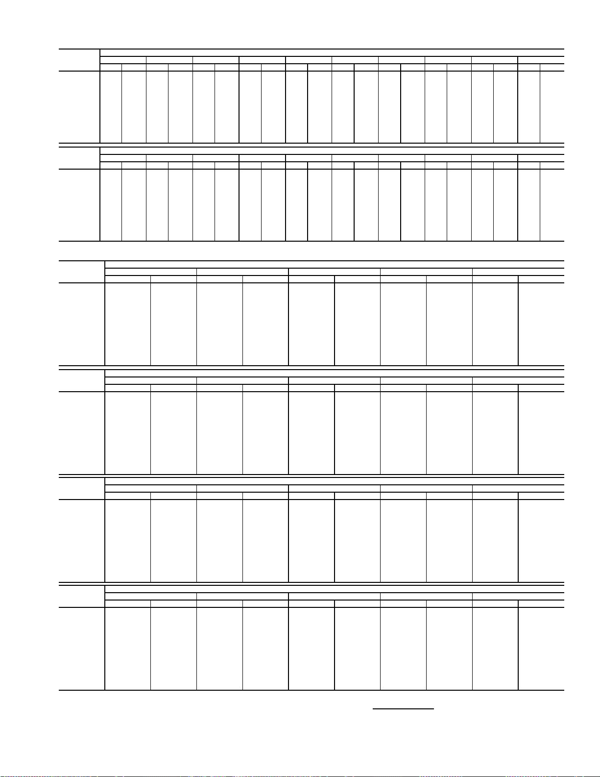
Table 9 — Fan Performance — 48AJ,AK,A2,A3050 Units
AIRFLOW
(Cfm)
8,000 512 2.98 560 3.38 604 3.79 647 4.20 688 4.62 728 5.05 766 5.49 803 5.94 839 6.40 874 6.86
9,000 561 3.90 604 4.33 645 4.77 685 5.20 723 5.65 760 6.10 796 6.55 831 7.02 864 7.49 897 7.97
10,000 611 5.00 651 5.45 689 5.91 725 6.37 761 6.84 795 7.31 829 7.79 861 8.27 893 8.76 925 9.26
11,000 662 6.27 699 6.75 734 7.23 768 7.72 801 8.21 833 8.71 865 9.20 895 9.71 925 10.21 955 10.73
12,000 714 7.74 748 8.24 780 8.75 812 9.26 843 9.77 873 10.29 903 10.81 932 11.33 960 11.86 988 12.39
13,000 766 9.41 798 9.93 828 10.46 858 11.00 887 11.54 916 12.08 944 12.62 971 13.16 998 13.71 1024 14.26
14,000 819 11.29 848 11.84 877 12.39 905 12.95 932 13.51 959 14.07 986 14.63 1012 15.20 1037 15.77 1062 16.34
15,000 872 13.40 899 13.96 926 14.54 953 15.11 979 15.70 1004 16.28 1029 16.87 1054 17.46 1078 18.05 1102 18.64
16,000 925 15.74 951 16.32 976 16.91 1001 17.51 1026 18.12 1050 18.72 1074 19.33 1097 19.94 1121 20.55 1143 21.17
17,000 979 18.32 1003 18.92 1027 19.53 1051 20.15 1074 20.77 1097 21.40 1120 22.03 1142 22.66 1164 23.29 1186 23.93
18,000 1032 21.15 1055 21.77 1078 22.40 1100 23.04 1123 23.68 1145 24.33 1166 24.98 1188 25.63 1209 26.28 1230 26.93
19,000 1086 24.24 1108 24.88 1129 25.52 1151 26.18 1172 26.84 1193 27.51 1214 28.18 1234 28.85 1255 29.52 1275 30.19
20,000 1140 27.60 1161 28.25 1181 28.92 1202 29.59 1222 30.27 1242 30.95 1262 31.64 1281 32.33 — — — —
AIRFLOW
(Cfm)
8,000 907 7.34 940 7.81 971 8.30 1001 8.79 1030 9.29 1059 9.79 1086 10.29 1113 10.80 1139 11.31 1164 11.83
9,000 930 8.46 961 8.95 991 9.46 1021 9.97 1050 10.48 1078 11.00 1105 11.52 1131 12.05 1157 12.58 1183 13.12
10,000 955 9.76 985 10.27 1014 10.79 1043 11.31 1071 11.84 1098 12.37 1125 12.91 1151 13.46 1177 14.01 1202 14.56
11,000 984 11.25 1012 11.77 1040 12.30 1068 12.84 1095 13.38 1121 13.93 1147 14.49 1172 15.05 1197 15.61 1222 16.18
12,000 1016 12.93 1043 13.47 1069 14.02 1095 14.57 1121 15.13 1147 15.69 1172 16.26 1196 16.83 1220 17.41 1244 18.00
13,000 1050 14.82 1076 15.38 1101 15.94 1126 16.51 1151 17.08 1175 17.66 1199 18.24 1223 18.83 1246 19.42 1269 20.02
14,000 1087 16.92 1111 17.49 1136 18.07 1159 18.66 1183 19.25 1206 19.84 1229 20.44 1252 21.04 1274 21.64 1296 22.25
15,000 1126 19.23 1149 19.83 1172 20.43 1195 21.03 1217 21.64 1239 22.25 1261 22.86 1283 23.48 — — — —
16,000 1166 21.78 1188 22.40 1210 23.01 1232 23.64 1253 24.26 1275 24.89 1296 25.52 — — — — — —
17,000 1208 24.56 1229 25.20 1250 25.84 1271 26.48 1291 27.12 ——————————
18,000 1250 27.59 1271 28.25 1291 28.91 ——————————————
19,000 1294 30.87 — — — ———————————————
20,000 ————————————————————
0.2 0.4 0.6 0.8 1.0 1.2 1.4 1.6 1.8 2.0
RpmBhpRpmBhpRpmBhpRpmBhpRpmBhpRpmBhpRpmBhpRpmBhpRpmBhpRpmBhp
2.2 2.4 2.6 2.8 3.0 3.2 3.4 3.6 3.8 4.0
RpmBhpRpmBhpRpmBhpRpmBhpRpmBhpRpmBhpRpmBhpRpmBhpRpmBhpRpmBhp
AVAILABLE E XTERNAL STATIC PRESSURE (in. wg)
AVAILABLE E XTERNAL STATIC PRESSURE (in. wg)
Table 10 — Fan Performance — 48AJ,AK051 Units
AIRFLOW
(Cfm)
10,000 419 2.89 483 3.54 538 4.25 587 5.00 632 5.79
12,000 476 4.33 534 5.04 585 5.78 632 6.56 674 7.39
13,000 506 5.21 561 5.94 610 6.70 655 7.50 697 8.34
14,000 536 6.18 588 6.96 636 7.74 680 8.56 720 9.41
15,000 566 7.28 617 8.09 662 8.90 704 9.73 744 10.59
16,000 597 8.48 645 9.34 689 10.17 730 11.02 768 11.90
17,000 628 9.80 674 10.71 717 11.58 756 12.45 793 13.34
18,000 659 11.25 704 12.21 745 13.11 783 14.00 819 14.91
19,000 691 12.82 734 13.84 773 14.77 810 15.69 845 16.62
20,000 723 14.53 764 15.60 802 16.57 838 17.52 872 18.47
21,000 755 16.37 794 17.49 831 18.51 866 19.49 899 20.47
22,000 787 18.35 825 19.53 861 20.59 894 21.60 927 22.61
23,000 819 20.48 856 21.71 890 22.81 923 23.87 954 24.90
24,000 851 22.75 887 24.04 920 25.19 952 26.28 983 27.34
25,000 883 25.17 918 26.52 951 27.72 982 28.84 1011 29.94
AIRFLOW
(Cfm)
10,000 673 6.60 711 7.42 747 8.26 782 9.10 815 9.96
12,000 714 8.24 751 9.12 786 10.02 819 10.92 851 11.85
13,000 735 9.22 772 10.11 806 11.03 839 11.97 870 12.92
14,000 758 10.30 793 11.21 827 12.15 859 13.11 890 14.08
15,000 781 11.50 816 12.43 849 13.38 881 14.35 911 15.35
16,000 804 12.82 839 13.76 871 14.73 902 15.72 932 16.73
17,000 829 14.27 862 15.23 894 16.21 925 17.21 954 18.24
18,000 853 15.85 886 16.82 918 17.82 948 18.84 977 19.88
19,000 879 17.58 911 18.56 942 19.57 971 20.60 1000 21.65
20,000 905 19.44 936 20.44 966 21.45 995 22.50 1023 23.57
21,000 931 21.46 961 22.47 991 23.50 1019 24.55 1047 25.63
22,000 958 23.62 987 24.64 1016 25.69 1044 26.76 1071 27.84
23,000 985 25.93 1014 26.97 1042 28.03 1069 29.11 1096 30.21
24,000
25,000 1040 31.02 1068 32.11 1095 33.21 1121 34.31 1147 35.44
AIRFLOW
(Cfm)
10,000 846 10.82 876 11.69 906 12.56 934 13.44 961 14.32
12,000 881 12.78 911 13.72 939 14.67 967 15.62 993 16.58
13,000 900 13.88 929 14.85 957 15.82 984 16.81 1011 17.80
14,000 920 15.06 948 16.06 976 17.07 1003 18.08 1029 19.11
15,000 940 16.36 968 17.38 996 18.41 1022 19.45 1048 20.50
16,000 961 17.76 989 18.80 1016 19.86 1042 20.92 1067 22.00
17,000 983 19.28 1010 20.34 1036 21.42 1062 22.51 1087 23.60
18,000 1005 20.94 1032 22.01 1058 23.11 1083 24.21 1108 25.33
19,000 1027 22.72 1054 23.81 1080 24.92 1105 26.04 1129 27.18
20,000 1050 24.65 1076 25.76 1102 26.88 1126 28.01 1151 29.17
21,000 1073 26.73 1099 27.84 1124 28.97 1149 30.13 1173 31.29
22,000 1097 28.95 1123 30.08 1147 31.22 1172 32.39 1195 33.56
23,000 1122 31.33 1147 32.47 1171 33.63 1195 34.80 — —
24,000 1146 33.87 1171 35.02 1195 36.19 — — — —
25,000 1171 36.58 1196 37.74 ——————
AIRFLOW
(Cfm)
10,000 988 15.21 1014 16.09 1039 16.98 1063 17.88 1087 18.77
12,000 1019 17.54 1045 18.51 1069 19.48 1093 20.45 1117 21.43
13,000 1036 18.80 1061 19.80 1086 20.81 1109 21.82 1133 22.84
14,000 1054 20.13 1079 21.17 1103 22.21 1126 23.26 1149 24.31
15,000 1073 21.56 1097 22.63 1121 23.70 1144 24.78 1167 25.86
16,000 1092 23.08 1116 24.17 1140 25.28 1162 26.38 1185 27.49
17,000 1112 24.71 1135 25.83 1159 26.95 1181 28.09 — —
18,000 1132 26.46 1156 27.60 1178 28.74 — — — —
19,000 1153 28.33 1176 29.48 1199 30.65 — — — —
20,000 1174 30.33 1197 31.50 ——————
21,000 119632.47————————
22,000 ——————————
23,000 ——————————
24,000 ——————————
25,000 ——————————
LEGEND
Bhp — Brake Horsepower
edb — Entering Dry Bulb
ewb — Entering Wet Bulb
NOTES:
1. Fan performance is based on wet coils, economizer, roof curb, cabinet losses, and clean 2-in.
filters.
0.2 0.4 0.6 0.8 1.0
Rpm Bhp Rpm Bhp Rpm Bhp Rpm Bhp Rpm Bhp
1.2 1.4 1.6 1.8 2.0
Rpm Bhp Rpm Bhp Rpm Bhp Rpm Bhp Rpm Bhp
1012 28.40 1041 29.46 1068 30.54 1095 31.63 1121 32.74
2.2 2.4 2.6 2.8 3.0
Rpm Bhp Rpm Bhp Rpm Bhp Rpm Bhp Rpm Bhp
3.2 3.4 3.6 3.8 4.0
Rpm Bhp Rpm Bhp Rpm Bhp Rpm Bhp Rpm Bhp
AVAILABLE EXTERNAL STATIC PRESSURE (in. wg)
AVAILABLE EXTERNAL STATIC PRESSURE (in. wg)
AVAILABLE EXTERNAL STATIC PRESSURE (in. wg)
AVAILABLE EXTERNAL STATIC PRESSURE (in. wg)
2. Conversion — Bhp to watts:
Watts =
3. Variable air volume units will operate down to 70 cfm/ton. Performance at 70 cfm/ton is limited to
unloaded operation and may be additionally limited by edb and ewb conditions.
Bhp x 746
Motor efficiency
11
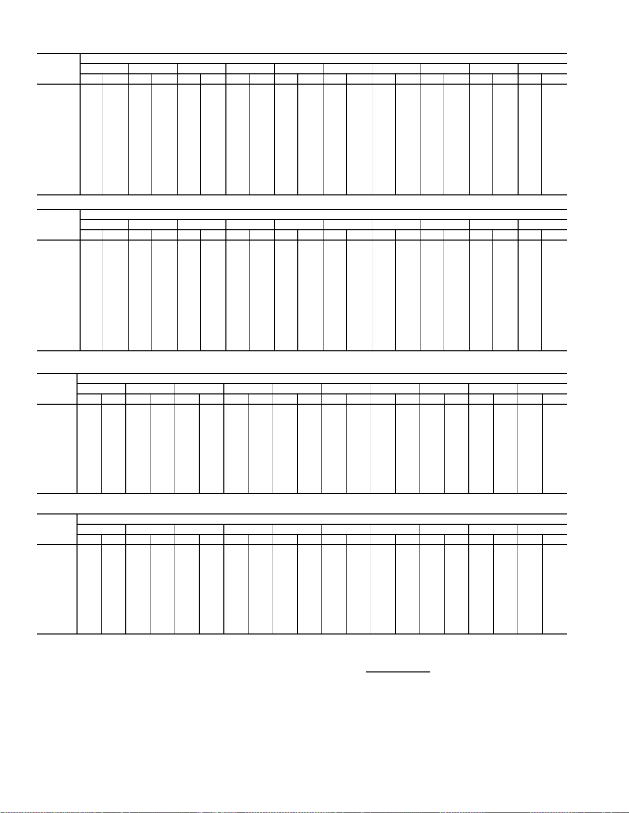
Table 11 — Fan Performance — 48AJ,AK,A2,A3060 Units
AIRFLOW
(Cfm)
12,000 476 4.33 534 5.04 585 5.78 632 6.56 674 7.39 714 8.24 751 9.12 786 10.02 819 10.93 851 11.85
14,000 536 6.19 588 6.96 636 7.74 680 8.56 720 9.41 758 10.30 793 11.21 827 12.15 859 13.11 890 14.08
15,000 566 7.28 617 8.09 662 8.90 704 9.73 744 10.59 781 11.50 816 12.42 849 13.38 881 14.36 911 15.35
16,000 597 8.48 645 9.34 689 10.17 730 11.02 768 11.90 804 12.82 839 13.76 871 14.73 902 15.72 932 16.73
17,000 628 9.80 674 10.71 717 11.58 756 12.45 793 13.34 829 14.27 862 15.23 894 16.21 925 17.21 954 18.24
18,000 659 11.25 704 12.21 745 13.11 783 14.00 819 14.91 853 15.85 886 16.82 918 17.82 948 18.84 977 19.88
19,000 691 12.82 734 13.84 773 14.77 810 15.69 845 16.62 879 17.58 911 18.56 942 19.57 971 20.60 1000 21.65
20,000 723 14.53 764 15.60 802 16.57 838 17.52 872 18.47 905 19.44 936 20.44 966 21.45 995 22.50 1023 23.57
21,000 755 16.37 794 17.49 831 18.51 866 19.49 899 20.47 931 21.46 961 22.47 991 23.50 1019 24.55 1047 25.63
22,000 787 18.35 825 19.53 861 20.59 894 21.60 927 22.61 958 23.62 987 24.64 1016 25.69 1044 26.76 1071 27.84
23,000 819 20.48 856 21.71 890 22.81 923 23.87 954 24.90 985 25.93 1014 26.97 1042 28.03 1069 29.11 1096 30.21
24,000 851 22.75 887 24.04 920 25.19 952 26.28 983 27.34 1012 28.40 1041 29.46 1068 30.54 1095 31.63 1121 32.74
25,000 883 25.17 918 26.52 951 27.72 982 28.84 1011 29.94 1040 31.02 1068 32.11 1095 33.21 1121 34.31 1147 35.44
26,000 916 27.76 950 29.15 981 30.40 1011 31.57 1040 32.70 1068 33.81 1095 34.92 1122 36.04 1147 37.16 1172 38.30
27,000 948 30.49 981 31.95 1012 33.24 1041 34.46 1070 35.62 1097 36.76 1123 37.90 1149 39.04 1174 40.18 1199 41.34
0.2 0.4 0.6 0.8 1.0 1.2 1.4 1.6 1.8 2.0
Rpm Bhp Rpm Bhp Rpm Bhp Rpm Bhp Rpm Bhp Rpm Bhp Rpm Bhp Rpm Bhp Rpm Bhp Rpm Bhp
AVAILABLE EXTERNAL STATIC PRESSURE (in. wg)
AIRFLOW
(Cfm)
12,000 881 12.78 911 13.72 939 14.67 967 15.62 993 16.58 1019 17.54 1045 18.51 1069 19.48 1093 20.45 1117 21.43
14,000 920 15.06 948 16.06 976 17.07 1003 18.08 1029 19.11 1054 20.13 1079 21.17 1103 22.21 1126 23.26 1149 24.31
15,000 940 16.36 968 17.38 996 18.41 1022 19.45 1048 20.50 1073 21.56 1097 22.63 1121 23.70 1144 24.78 1167 25.86
16,000 961 17.76 989 18.80 1016 19.86 1042 20.92 1067 22.00 1092 23.08 1116 24.17 1140 25.28 1162 26.38 1185 27.49
17,000 983 19.28 1010 20.34 1036 21.42 1062 22.51 1087 23.60 1112 24.71 1135 25.83 1159 26.95 1181 28.09 — —
18,000 1005 20.94 1032 22.01 1058 23.11 1083 24.21 1108 25.33 1132 26.46 1156 27.60 1178 28.74 — — — —
19,000 1027 22.72 1054 23.81 1080 24.92 1105 26.04 1129 27.18 1153 28.33 1176 29.48 1199 30.65 — — — —
20,000 1050 24.65 1076 25.76 1102 26.88 1126 28.01 1151 29.17 1174 30.33 1197 31.50 — — — — — —
21,000 1073 26.73 1099 27.84 1124 28.97 1149 30.13 1173 31.29 1196 32.47 — ———————
22,000 1097 28.95 1123 30.08 1147 31.22 1172 32.39 1195 33.56 — — — ———————
23,000 112231.33114732.47117133.63119534.80————————————
24,000 114633.87117135.02119536.19——————————————
25,000 117136.58119637.74————————————————
26,000 119739.46——————————————————
27,000 ————————————————————
2.2 2.4 2.6 2.8 3.0 3.2 3.4 3.6 3.8 4.0
Rpm Bhp Rpm Bhp Rpm Bhp Rpm Bhp Rpm Bhp Rpm Bhp Rpm Bhp Rpm Bhp Rpm Bhp Rpm Bhp
AVAILABLE EXTERNAL STATIC PRESSURE (in. wg)
Table 12 — Fan Performance — 50AJ,AK020,025 and 50A2,A3020 Units
AIRFLOW
(CFM)
4,000 311 0.54 390 0.71 457 0.88 515 1.05 567 1.21 613 1.38 656 1.55 696 1.71 733 1.88 768 2.04
5,000 347 0.84 417 1.02 480 1.21 536 1.40 587 1.59 633 1.78 676 1.97 716 2.16 753 2.34 788 2.52
6,000 387 1.25 450 1.43 507 1.63 560 1.84 609 2.05 654 2.26 696 2.47 735 2.68 773 2.88 808 3.09
7,000 430 1.77 488 1.96 540 2.17 588 2.38 634 2.61 677 2.83 718 3.06 756 3.29 793 3.51 828 3.74
7,500 452 2.07 507 2.27 557 2.48 604 2.70 648 2.93 690 3.16 730 3.40 768 3.63 804 3.87 839 4.10
8,000 474 2.41 528 2.61 576 2.82 620 3.04 663 3.28 704 3.52 743 3.76 780 4.00 816 4.24 850 4.48
9,000 519 3.19 570 3.39 614 3.60 656 3.83 696 4.07 734 4.32 771 4.57 806 4.82 840 5.08 873 5.34
10,000 565 4.10 613 4.31 655 4.53 694 4.76 731 5.00 767 5.26 802 5.51 835 5.78 868 6.04 900 6.31
11,000 611 5.17 657 5.37 697 5.60 734 5.84 769 6.08 803 6.34 836 6.60 868 6.87 899 7.15 929 7.42
12,000 658 6.39 702 6.60 741 6.83 776 7.07 809 7.32 841 7.58 872 7.85 902 8.12 932 8.40 960 8.68
12,500 681 7.06 725 7.27 763 7.50 797 7.74 830 8.00 861 8.26 891 8.53 920 8.80 949 9.08 977 9.37
13,000 705 7.77 748 7.98 785 8.21 819 8.46 850 8.71 881 8.98 910 9.25 939 9.53 967 9.81 994 10.10
0.2 0.4 0.6 0.8 1.0 1.2 1.4 1.6 1.8 2.0
Rpm Bhp Rpm Bhp Rpm Bhp Rpm Bhp Rpm Bhp Rpm Bhp Rpm Bhp Rpm Bhp Rpm Bhp Rpm Bhp
AVAILABLE EXTERNAL STATIC PRESSURE (in. wg)
AIRFLOW
(CFM)
4,000 802 2.21 833 2.38 864 2.55 893 2.71 921 2.88 949 3.06 975 3.23 1001 3.40 1026 3.58 1050 3.75
5,000 822 2.71 854 2.89 885 3.08 914 3.26 943 3.45 970 3.64 997 3.82 1023 4.01 1048 4.20 1072 4.39
6,000 842 3.29 874 3.50 905 3.70 934 3.90 963 4.10 991 4.31 1017 4.51 1043 4.71 1069 4.91 1093 5.12
7,000 862 3.96 894 4.19 924 4.41 954 4.63 983 4.85 1010 5.07 1037 5.29 1063 5.51 1089 5.72 1113 5.94
7,500 872 4.33 904 4.56 934 4.79 964 5.02 993 5.25 1020 5.48 1047 5.71 1073 5.94 1099 6.16 1123 6.39
8,000 883 4.73 914 4.97 945 5.21 974 5.45 1003 5.68 1030 5.92 1057 6.16 1083 6.39 1108 6.63 1133 6.87
9,000 905 5.60 936 5.85 966 6.11 995 6.37 1023 6.62 1051 6.88 1077 7.13 1103 7.38 1129 7.64 1153 7.89
10,000 931 6.58 961 6.85 990 7.13 1018 7.40 1046 7.67 1073 7.94 1099 8.21 1124 8.48 1149 8.75 1174 9.02
11,000 958 7.70 987 7.99 1015 8.27 1043 8.55 1070 8.84 1096 9.12 1122 9.41 1147 9.69 1171 9.98 1195 10.26
12,000 989 8.97 1016 9.26 1043 9.55 1070 9.85 1096 10.14 1121 10.44 1146 10.73 1171 11.03 1195 11.33 — —
12,500 1005 9.66 1032 9.95 1058 10.25 1084 10.55 1110 10.85 1135 11.15 1159 11.45 1183 11.75 — — — —
13,000 1021 10.39 1048 10.69 1074 10.99 1099 11.29 1124 11.59 1149 11.90 1173 12.20 1197 12.51 — — — —
LEGEND
Bhp — Brake Horsepower
edb — Entering Dry Bulb
ewb — Entering Wet Bulb
NOTES:
1. Fan performance is based on wet coils, economizer, roof curb, cabinet
losses, and clean 2-in. filters.
2.2 2.4 2.6 2.8 3.0 3.2 3.4 3.6 3.8 4.0
Rpm Bhp Rpm Bhp Rpm Bhp Rpm Bhp Rpm Bhp Rpm Bhp Rpm Bhp Rpm Bhp Rpm Bhp Rpm Bhp
AVAILABLE EXTERNAL STATIC PRESSURE (in. wg)
2. Conversion — Bhp to watts:
Watts =
3. Variable air volume units will operate down to 70 cfm/ton. Performance at
70 cfm/ton is limited to unloaded operation and may be additionally limited
by edb and ewb conditions.
Bhp x 746
Motor efficiency
12
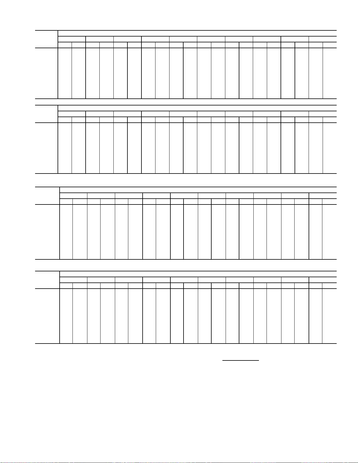
Table 13 — Fan Performance — 50AJ,AK027,030 and 50A2,A3025-030 Units
AIRFLOW
(CFM)
4,000 314 0.54 394 0.72 460 0.89 517 1.05 569 1.22 615 1.39 658 1.55 697 1.72 734 1.88 769 2.05
5,000 352 0.85 422 1.03 484 1.22 540 1.42 590 1.61 636 1.79 678 1.98 718 2.17 755 2.35 791 2.54
6,000 394 1.26 456 1.45 513 1.65 565 1.86 613 2.07 658 2.28 700 2.49 739 2.70 776 2.90 811 3.11
7,000 438 1.79 495 1.98 546 2.19 594 2.41 640 2.64 682 2.86 723 3.09 761 3.32 798 3.54 833 3.77
8,000 483 2.44 536 2.64 583 2.85 628 3.08 670 3.32 710 3.55 749 3.80 786 4.04 821 4.28 855 4.52
9,000 530 3.23 579 3.43 623 3.65 664 3.88 704 4.12 741 4.37 778 4.62 813 4.88 847 5.13 880 5.39
10,000 577 4.15 624 4.36 665 4.58 703 4.82 740 5.06 776 5.32 810 5.58 843 5.84 876 6.11 907 6.38
11,000 625 5.22 669 5.44 708 5.67 744 5.91 779 6.16 813 6.41 845 6.68 877 6.95 907 7.22 937 7.50
12,000 674 6.45 715 6.67 753 6.90 787 7.15 820 7.40 851 7.67 882 7.93 912 8.21 941 8.49 970 8.78
13,000 722 7.85 762 8.07 798 8.30 831 8.55 862 8.81 892 9.08 921 9.35 950 9.63 977 9.92 1005 10.21
14,000 771 9.41 810 9.64 844 9.88 875 10.13 905 10.39 934 10.66 962 10.94 989 11.22 1015 11.51 1041 11.81
15,000 821 11.15 857 11.38 890 11.62 921 11.88 949 12.14 977 12.42 1004 12.70 1030 12.99 1055 13.28 1080 13.58
0.2 0.4 0.6 0.8 1.0 1.2 1.4 1.6 1.8 2.0
Rpm Bhp Rpm Bhp Rpm Bhp Rpm Bhp Rpm Bhp Rpm Bhp Rpm Bhp Rpm Bhp Rpm Bhp Rpm Bhp
AVAILABLE EXTERNAL STATIC PRESSURE (in. wg)
AIRFLOW
(CFM)
4,000 803 2.22 835 2.38 865 2.55 894 2.72 923 2.89 950 3.06 976 3.24 1002 3.41 1027 3.58 1051 3.76
5,000 824 2.72 856 2.91 887 3.09 916 3.28 945 3.46 972 3.65 999 3.83 1024 4.02 1049 4.21 1074 4.40
6,000 845 3.31 877 3.52 908 3.72 937 3.92 966 4.12 993 4.32 1020 4.53 1046 4.73 1071 4.93 1096 5.14
7,000 866 3.99 898 4.21 928 4.43 958 4.66 986 4.88 1014 5.10 1041 5.31 1067 5.53 1092 5.75 1116 5.97
8,000 888 4.77 919 5.01 950 5.25 979 5.49 1007 5.72 1035 5.96 1061 6.20 1087 6.43 1113 6.67 1137 6.90
9,000 912 5.65 942 5.90 972 6.16 1001 6.42 1029 6.67 1056 6.93 1083 7.18 1108 7.43 1134 7.69 1158 7.94
10,000 938 6.65 968 6.92 997 7.19 1025 7.46 1052 7.73 1079 8.00 1105 8.27 1130 8.54 1155 8.81 1180 9.08
11,000 967 7.78 995 8.07 1023 8.35 1051 8.63 1077 8.92 1103 9.20 1129 9.49 1154 9.77 1178 10.06 — —
12,000 998 9.07 1025 9.35 1052 9.65 1078 9.94 1104 10.24 1130 10.54 1154 10.83 1179 11.13 — — — —
13,000 1031 10.50 1058 10.80 1083 11.10 1109 11.40 1133 11.71 1158 12.01 1182 12.32 — — — — — —
14,000 1067 12.10 1092 12.41 1117 12.71 1141 13.02 1165 13.33 1188 13.65 — — — — — — — —
15,000 1104 13.88 1128 14.19 1152 14.50 1175 14.81 1198 15.13 — — — — — — — — — —
2.2 2.4 2.6 2.8 3.0 3.2 3.4 3.6 3.8 4.0
Rpm Bhp Rpm Bhp Rpm Bhp Rpm Bhp Rpm Bhp Rpm Bhp Rpm Bhp Rpm Bhp Rpm Bhp Rpm Bhp
AVAILABLE EXTERNAL STATIC PRESSURE (in. wg)
Table 14 — Fan Performance — 50AJ,AKA2,A3035 Units
AIRFLOW
(Cfm)
7,000 503 1.96 553 2.22 601 2.47 646 2.72 689 2.97 730 3.22 768 3.46 804 3.70 839 3.94 872 4.17
8,000 553 2.62 599 2.89 643 3.16 684 3.43 724 3.70 763 3.97 799 4.23 834 4.50 868 4.76 901 5.02
9,000 605 3.39 647 3.68 687 3.97 726 4.26 763 4.55 798 4.83 833 5.12 867 5.40 899 5.68 930 5.96
10,000 657 4.29 696 4.61 733 4.91 769 5.22 803 5.52 837 5.82 870 6.12 901 6.42 932 6.72 962 7.02
10,500 684 4.80 721 5.12 757 5.43 791 5.75 825 6.06 857 6.37 889 6.68 920 6.98 950 7.29 979 7.60
11,000 710 5.33 747 5.66 781 5.99 814 6.31 847 6.63 878 6.95 909 7.26 939 7.58 968 7.89 997 8.21
12,000 764 6.52 798 6.86 830 7.21 861 7.54 891 7.88 921 8.21 950 8.54 978 8.87 1006 9.20 1033 9.53
13,000 818 7.85 849 8.21 880 8.57 909 8.92 938 9.27 966 9.62 993 9.97 1020 10.31 1046 10.66 1072 11.00
14,000 872 9.33 901 9.71 930 10.09 958 10.45 985 10.82 1012 11.19 1037 11.55 1063 11.91 1088 12.27 1113 12.63
15,000 926 10.98 954 11.37 981 11.76 1008 12.15 1033 12.53 1059 12.91 1083 13.28 1108 13.66 1131 14.03 1155 14.40
16,000 980 12.79 1007 13.20 1033 13.60 1058 14.00 1082 14.40 1106 14.79 1130 15.18 1153 15.57 1176 15.96 1199 16.35
17,000 1035 14.77 1060 15.19 1085 15.61 1109 16.03 1132 16.44 1155 16.84 1178 17.25 1200 17.65 1222 18.05 1243 18.46
17,500 1062 15.83 1087 16.25 1111 16.68 1134 17.10 1157 17.52 1180 17.94 1202 18.35 1224 18.76 1245 19.17 1266 19.58
AIRFLOW
(Cfm)
7,000 903 4.40 933 4.62 962 4.84 990 5.06 1017 5.27 1043 5.48 1068 5.69 1092 5.89 1116 6.09 1139 6.28
8,000 932 5.27 962 5.52 991 5.77 1019 6.02 1045 6.26 1071 6.50 1097 6.73 1121 6.96 1145 7.19 1168 7.42
9,000 961 6.24 990 6.52 1019 6.79 1047 7.06 1073 7.33 1099 7.59 1125 7.85 1149 8.11 1173 8.37 1196 8.62
10,000 992 7.32 1020 7.62 1048 7.91 1075 8.20 1102 8.49 1127 8.78 1152 9.07 1177 9.35 1201 9.63 1224 9.91
10,500 1008 7.90 1036 8.21 1063 8.51 1090 8.82 1116 9.12 1142 9.41 1166 9.71 1191 10.01 1214 10.30 1238 10.59
11,000 1025 8.52 1052 8.84 1079 9.15 1105 9.46 1131 9.77 1156 10.08 1181 10.39 1205 10.69 1228 10.99 1252 11.29
12,000 1060 9.86 1086 10.19 1112 10.52 1137 10.85 1162 11.17 1187 11.50 1211 11.82 1234 12.15 1257 12.47 1280 12.79
13,000 1097 11.35 1122 11.69 1147 12.03 1171 12.37 1195 12.72 1219 13.06 1242 13.40 1265 13.74 1287 14.08 — —
14,000 1137 12.98 1161 13.34 1184 13.69 1208 14.05 1231 14.41 1253 14.76 1276 15.12 1298 15.47 — — — —
15,000 1178 14.77 1201 15.15 1223 15.51 1246 15.88 1268 16.25 1289 16.62 ————————
16,000 122116.73124317.11126417.50128617.88————————————
17,000 126518.85128619.25————————————————
17,500 128719.98——————————————————
LEGEND
Bhp — Brake Horsepower
edb — Entering Dry Bulb
ewb — Entering Wet Bulb
NOTES:
1. Fan performance is based on wet coils, economizer, roof curb, cabinet
losses, and clean 2-in. filters.
0.2 0.4 0.6 0.8 1.0 1.2 1.4 1.6 1.8 2.0
Rpm Bhp Rpm Bhp Rpm Bhp Rpm Bhp Rpm Bhp Rpm Bhp Rpm Bhp Rpm Bhp Rpm Bhp Rpm Bhp
2.2 2.4 2.6 2.8 3.0 3.2 3.4 3.6 3.8 4.0
Rpm Bhp Rpm Bhp Rpm Bhp Rpm Bhp Rpm Bhp Rpm Bhp Rpm Bhp Rpm Bhp Rpm Bhp Rpm Bhp
AVAILABLE EXTERNAL STATIC PRESSURE (in. wg)
AVAILABLE EXTERNAL STATIC PRESSURE (in. wg)
2. Conversion — Bhp to watts:
Watts =
3. Variable air volume units will operate down to 70 cfm/ton. Performance at
70 cfm/ton is limited to unloaded operation and may be additionally limited
by edb and ewb conditions.
Bhp x 746
Motor efficiency
13
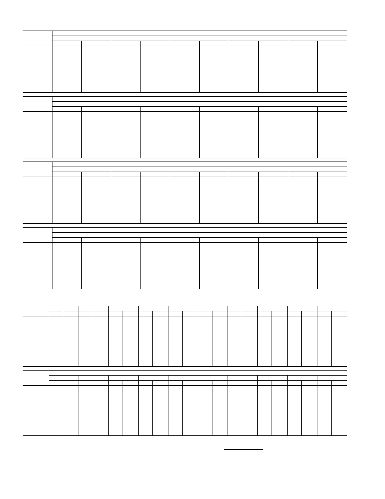
Table 15 — Fan Performance — 50AJ,AK036 Units
AIRFLOW
(Cfm)
7,000 431 1.99 484 2.35 534 2.72 580 3.08 625 3.46
8,000 475 2.69 523 3.08 569 3.47 612 3.86 653 4.26
9,000 521 3.53 565 3.94 606 4.36 646 4.78 684 5.20
10,000 568 4.52 608 4.96 646 5.40 683 5.84 719 6.29
11,000 615 5.68 652 6.14 687 6.60 722 7.07 755 7.55
12,000 663 7.01 697 7.49 730 7.98 762 8.47 794 8.97
13,000 712 8.53 743 9.03 774 9.54 804 10.05 834 10.57
14,000 760 10.24 790 10.76 819 11.29 847 11.82 875 12.36
15,000 809 12.15 837 12.69 864 13.24 891 13.79 917 14.35
16,000 859 14.27 885 14.83 910 15.40 936 15.97 960 16.55
17,000 908 16.61 933 17.19 957 17.77 981 18.36 1004 18.96
17,500 933 17.87 957 18.45 981 19.04 1004 19.64 1027 20.25
AIRFLOW
(Cfm)
7,000 667 3.85 707 4.24 746 4.65 783 5.07 819 5.49
8,000 692 4.66 730 5.07 767 5.49 802 5.92 836 6.36
9,000 721 5.63 757 6.06 791 6.49 825 6.94 857 7.39
10,000 753 6.74 787 7.20 819 7.65 851 8.11 882 8.58
11,000 788 8.02 819 8.50 850 8.97 880 9.46 909 9.94
12,000 824 9.47 854 9.96 883 10.47 912 10.97 939 11.48
13,000 862 11.09 891 11.61 918 12.13 945 12.66 972 13.19
14,000 902 12.90 929 13.45 955 13.99 981 14.54 1006 15.09
15,000 943 14.91 968 15.48 993 16.04 1018 16.62 1042 17.18
16,000 985 17.13 1009 17.71 1033 18.30 1056 18.89 1079 19.48
17,000 1028 19.56 1051 20.16 1073 20.77 1096 21.38 1118 21.99
17,500 1049 20.86 1072 21.47 1094 22.09 1116 22.71 1137 23.33
AIRFLOW
(Cfm)
7,000 854 5.93 887 6.37 919 6.82 950 7.28 980 7.74
8,000 870 6.81 902 7.26 933 7.73 964 8.20 993 8.67
9,000 889 7.85 920 8.31 950 8.79 979 9.27 1008 9.75
10,000 912 9.05 941 9.53 970 10.02 998 10.51 1026 11.00
11,000 938 10.43 966 10.92 993 11.42 1020 11.93 1047 12.44
12,000 967 11.98 993 12.49 1020 13.01 1046 13.53 1071 14.05
13,000 998 13.72 1023 14.25 1049 14.78 1073 15.32 1098 15.86
14,000 1031 15.64 1055 16.19 1079 16.75 1103 17.30 1126 17.86
15,000 1066 17.76 1089 18.33 1112 18.90 1135 19.48 1157 20.06
16,000 1102 20.08 1124 20.67 1147 21.26 1168 21.86 1190 22.46
17,000 1140 22.61 1161 23.22 1182 23.84 1203 24.45 1224 25.07
17,500 1159 23.95 1180 24.58 1201 25.21 1221 25.83 1242 26.46
AIRFLOW
(Cfm)
7,000 1009 8.21 1037 8.69 1064 9.17 1091 9.65 1116 10.14
8,000 1022 9.16 1050 9.65 1077 10.14 1104 10.64 1129 11.15
9,000 1036 10.25 1064 10.75 1090 11.26 1117 11.77 1142 12.29
10,000 1053 11.51 1080 12.02 1106 12.54 1131 13.06 1157 13.59
11,000 1073 12.95 1099 13.47 1124 14.00 1149 14.53 1173 15.07
12,000 1096 14.58 1121 15.11 1145 15.65 1169 16.19 1192 16.74
13,000 1121 16.40 1145 16.95 1168 17.50 1191 18.06 1214 18.62
14,000 1149 18.42 1172 18.98 1195 19.55 1217 20.12 1239 20.69
15,000 1179 20.63 1201 21.21 1223 21.80 1244 22.38 1265 22.97
16,000 1211 23.06 1232 23.66 1253 24.26 1274 24.86 1294 25.46
17,000 1245 25.69 1265 26.31 1285 26.93 — — — —
17,500 126227.09128227.71——————
0.2 0.4 0.6 0.8 1.0
Rpm Bhp Rpm Bhp Rpm Bhp Rpm Bhp Rpm Bhp
1.2 1.4 1.6 1.8 2.0
Rpm Bhp Rpm Bhp Rpm Bhp Rpm Bhp Rpm Bhp
2.2 2.4 2.6 2.8 3.0
Rpm Bhp Rpm Bhp Rpm Bhp Rpm Bhp Rpm Bhp
3.2 3.4 3.6 3.8 4.0
Rpm Bhp Rpm Bhp Rpm Bhp Rpm Bhp Rpm Bhp
AVAILABLE EXTERNAL STATIC PRESSURE (in. wg)
AVAILABLE EXTERNAL STATIC PRESSURE (in. wg)
AVAILABLE EXTERNAL STATIC PRESSURE (in. wg)
AVAILABLE EXTERNAL STATIC PRESSURE (in. wg)
Table 16 — Fan Performance — 50AJ,AK,A2,A3040 Units
AIRFLOW
(Cfm)
8,000 475 2.69 523 3.08 569 3.47 612 3.86 653 4.26 692 4.66 730 5.07 767 5.49 802 5.92 836 6.36
9,000 521 3.53 565 3.94 606 4.36 646 4.78 684 5.20 721 5.63 757 6.06 791 6.49 825 6.94 857 7.39
10,000 568 4.52 608 4.96 646 5.40 683 5.84 719 6.29 753 6.74 787 7.20 819 7.65 851 8.11 882 8.58
11,000 615 5.68 652 6.14 687 6.60 722 7.07 755 7.55 788 8.02 819 8.50 850 8.97 880 9.46 909 9.94
12,000 663 7.01 697 7.49 730 7.98 762 8.47 794 8.97 824 9.47 854 9.96 883 10.47 912 10.97 939 11.48
13,000 712 8.53 743 9.03 774 9.54 804 10.05 834 10.57 862 11.09 891 11.61 918 12.13 945 12.66 972 13.19
14,000 760 10.24 790 10.76 819 11.29 847 11.82 875 12.36 902 12.90 929 13.45 955 13.99 981 14.54 1006 15.09
15,000 809 12.15 837 12.69 864 13.24 891 13.79 917 14.35 943 14.91 968 15.48 993 16.04 1018 16.62 1042 17.18
16,000 859 14.27 885 14.83 910 15.40 936 15.97 960 16.55 985 17.13 1009 17.71 1033 18.30 1056 18.89 1079 19.48
17,000 908 16.61 933 17.19 957 17.77 981 18.36 1004 18.96 1028 19.56 1051 20.16 1073 20.77 1096 21.38 1118 21.99
18,000 958 19.18 981 19.77 1004 20.37 1027 20.98 1049 21.60 1071 22.22 1093 22.84 1115 23.46 1136 24.09 1157 24.72
19,000 1007 21.98 1030 22.59 1052 23.21 1073 23.84 1095 24.47 1116 25.10 1137 25.74 1157 26.39 1178 27.04 1198 27.68
20,000 105725.02107925.65109926.29112026.93114027.58116128.23118128.89——————
AIRFLOW
(Cfm)
8,000 870 6.81 902 7.26 933 7.73 964 8.20 993 8.67 1022 9.16 1050 9.65 1077 10.14 1104 10.64 1129 11.15
9,000 889 7.85 920 8.31 950 8.79 979 9.27 1008 9.75 1036 10.25 1064 10.75 1090 11.26 1117 11.77 1142 12.29
10,000 912 9.05 941 9.53 970 10.02 998 10.51 1026 11.00 1053 11.51 1080 12.02 1106 12.54 1131 13.06 1157 13.59
11,000 938 10.43 966 10.92 993 11.42 1020 11.93 1047 12.44 1073 12.95 1099 13.47 1124 14.00 1149 14.53 1173 15.07
12,000 967 11.98 993 12.49 1020 13.01 1046 13.53 1071 14.05 1096 14.58 1121 15.11 1145 15.65 1169 16.19 1192 16.74
13,000 998 13.72 1023 14.25 1049 14.78 1073 15.32 1098 15.86 1121 16.40 1145 16.95 1168 17.50 1191 18.06 1214 18.62
14,000 1031 15.64 1055 16.19 1079 16.75 1103 17.30 1126 17.86 1149 18.42 1172 18.98 1195 19.55 1217 20.12 1239 20.69
15,000 1066 17.76 1089 18.33 1112 18.90 1135 19.48 1157 20.06 1179 20.63 1201 21.21 1223 21.80 1244 22.38 1265 22.97
16,000 1102 20.08 1124 20.67 1147 21.26 1168 21.86 1190 22.46 1211 23.06 1232 23.66 1253 24.26 1274 24.86 1294 25.46
17,000 114022.61116123.22118223.84120324.45122425.07124525.69126526.31128526.93————
18,000 117825.36119925.99121926.63124027.26126027.90127928.54129929.18——————
19,000 121828.34123828.99————————————————
20,000 ————————————————————
LEGEND
Bhp — Brake Horsepower
edb — Entering Dry Bulb
ewb — Entering Wet Bulb
NOTES:
1. Fan performance is based on wet coils, economizer, roof curb, cabinet losses, and clean
2-in. filters.
0.20.40.60.81.01.21.41.61.82.0
RpmBhpRpmBhpRpmBhpRpmBhpRpmBhpRpmBhpRpmBhpRpmBhpRpmBhpRpmBhp
2.22.42.62.83.03.23.43.63.84.0
RpmBhpRpmBhpRpmBhpRpmBhpRpmBhpRpmBhpRpmBhpRpmBhpRpmBhpRpmBhp
AVAILABLE EXTERNAL STATIC PRESSURE (in. wg)
AVAILABLE EXTERNAL STATIC PRESSURE (in. wg)
2. Conversion — Bhp to watts:
Watts =
3. Variable air volume units will operate down to 70 cfm/ton. Performance at 70 cfm/ton is
limited to unloaded operation and may be additionally limited by edb and ewb conditions.
Bhp x 746
Motor efficiency
14
Table 17 — Fan Performance — 50AJ,AK041 Units
AIRFLOW
(Cfm)
8,000 475 2.69 523 3.08 569 3.47 612 3.86 653 4.26
9,000 521 3.53 565 3.94 606 4.36 646 4.78 684 5.20
10,000 568 4.52 608 4.96 646 5.40 683 5.84 719 6.29
11,000 615 5.68 652 6.14 687 6.60 722 7.07 755 7.55
12,000 663 7.01 697 7.49 730 7.98 762 8.47 794 8.97
13,000 712 8.53 743 9.03 774 9.54 804 10.05 834 10.57
14,000 760 10.24 790 10.76 819 11.29 847 11.82 875 12.36
15,000 809 12.15 837 12.69 864 13.24 891 13.79 917 14.35
16,000 859 14.27 885 14.83 910 15.40 936 15.97 960 16.55
17,000 908 16.61 933 17.19 957 17.77 981 18.36 1004 18.96
18,000 958 19.18 981 19.77 1004 20.37 1027 20.98 1049 21.60
19,000 1007 21.98 1030 22.59 1052 23.21 1073 23.84 1095 24.47
20,000 1057 25.02 1079 25.65 1099 26.29 1120 26.93 1140 27.58
AIRFLOW
(Cfm)
8,000 692 4.66 730 5.07 767 5.49 802 5.92 836 6.36
9,000 721 5.63 757 6.06 791 6.49 825 6.94 857 7.39
10,000 753 6.74 787 7.20 819 7.65 851 8.11 882 8.58
11,000 788 8.02 819 8.50 850 8.97 880 9.46 909 9.94
12,000 824 9.47 854 9.96 883 10.47 912 10.97 939 11.48
13,000 862 11.09 891 11.61 918 12.13 945 12.66 972 13.19
14,000 902 12.90 929 13.45 955 13.99 981 14.54 1006 15.09
15,000 943 14.91 968 15.48 993 16.04 1018 16.62 1042 17.18
16,000 985 17.13 1009 17.71 1033 18.30 1056 18.89 1079 19.48
17,000 1028 19.56 1051 20.16 1073 20.77 1096 21.38 1118 21.99
18,000 1071 22.22 1093 22.84 1115 23.46 1136 24.09 1157 24.72
19,000 1116 25.10 1137 25.74 1157 26.39 1178 27.04 1198 27.68
20,000 116128.23118128.89——————
AIRFLOW
(Cfm)
8,000 870 6.81 902 7.26 933 7.73 964 8.20 993 8.67
9,000 889 7.85 920 8.31 950 8.79 979 9.27 1008 9.75
10,000 912 9.05 941 9.53 970 10.02 998 10.51 1026 11.00
11,000 938 10.43 966 10.92 993 11.42 1020 11.93 1047 12.44
12,000 967 11.98 993 12.49 1020 13.01 1046 13.53 1071 14.05
13,000 998 13.72 1023 14.25 1049 14.78 1073 15.32 1098 15.86
14,000 1031 15.64 1055 16.19 1079 16.75 1103 17.30 1126 17.86
15,000 1066 17.76 1089 18.33 1112 18.90 1135 19.48 1157 20.06
16,000 1102 20.08 1124 20.67 1147 21.26 1168 21.86 1190 22.46
17,000 1140 22.61 1161 23.22 1182 23.84 1203 24.45 1224 25.07
18,000 1178 25.36 1199 25.99 1219 26.63 1240 27.26 1260 27.90
19,000 121828.34123828.99——————
20,000 ——————————
AIRFLOW
(Cfm)
8,000 1022 9.16 1050 9.65 1077 10.14 1104 10.64 1129 11.15
9,000 1036 10.25 1064 10.75 1090 11.26 1117 11.77 1142 12.29
10,000 1053 11.51 1080 12.02 1106 12.54 1131 13.06 1157 13.59
11,000 1073 12.95 1099 13.47 1124 14.00 1149 14.53 1173 15.07
12,000 1096 14.58 1121 15.11 1145 15.65 1169 16.19 1192 16.74
13,000 1121 16.40 1145 16.95 1168 17.50 1191 18.06 1214 18.62
14,000 1149 18.42 1172 18.98 1195 19.55 1217 20.12 1239 20.69
15,000 1179 20.63 1201 21.21 1223 21.80 1244 22.38 1265 22.97
16,000 1211 23.06 1232 23.66 1253 24.26 1274 24.86 1294 25.46
17,000 1245 25.69 1265 26.31 1285 26.93 — — — —
18,000 127928.54129929.18——————
19,000 ——————————
20,000 ——————————
0.2 0.4 0.6 0.8 1.0
Rpm Bhp Rpm Bhp Rpm Bhp Rpm Bhp Rpm Bhp
1.2 1.4 1.6 1.8 2.0
Rpm Bhp Rpm Bhp Rpm Bhp Rpm Bhp Rpm Bhp
2.2 2.4 2.6 2.8 3.0
Rpm Bhp Rpm Bhp Rpm Bhp Rpm Bhp Rpm Bhp
3.2 3.4 3.6 3.8 4.0
Rpm Bhp Rpm Bhp Rpm Bhp Rpm Bhp Rpm Bhp
AVAILABLE EXTERNAL STATIC PRESSURE (in. wg)
AVAILABLE EXTERNAL STATIC PRESSURE (in. wg)
AVAILABLE EXTERNAL STATIC PRESSURE (in. wg)
AVAILABLE EXTERNAL STATIC PRESSURE (in. wg)
Table 18 — Fan Performance — 50AJ,AK,A2,A3050 Units
AIRFLOW
(Cfm)
8,000 485 2.76 532 3.15 577 3.54 620 3.94 661 4.34 700 4.74 737 5.16 774 5.58 809 6.01 843 6.45
9,000 530 3.62 574 4.03 615 4.45 655 4.87 692 5.29 729 5.72 764 6.15 798 6.59 832 7.03 864 7.49
10,000 577 4.62 617 5.06 655 5.50 692 5.95 727 6.40 761 6.85 794 7.30 827 7.76 858 8.22 889 8.69
11,000 625 5.80 661 6.26 697 6.73 731 7.20 764 7.67 796 8.14 827 8.62 858 9.10 888 9.58 917 10.07
12,000 673 7.15 707 7.63 740 8.12 772 8.62 803 9.11 833 9.61 863 10.11 891 10.61 920 11.12 947 11.62
13,000 722 8.69 753 9.19 784 9.70 814 10.22 843 10.74 872 11.26 900 11.78 927 12.31 954 12.83 980 13.36
14,000 771 10.43 800 10.95 829 11.48 857 12.01 885 12.55 912 13.10 938 13.64 964 14.19 990 14.74 1015 15.29
15,000 821 12.37 848 12.91 875 13.46 901 14.01 928 14.57 953 15.14 978 15.70 1003 16.27 1028 16.84 1052 17.41
16,000 870 14.52 896 15.08 922 15.65 947 16.22 971 16.80 996 17.39 1020 17.97 1043 18.56 1066 19.15 1089 19.75
17,000 920 16.89 945 17.48 969 18.06 993 18.65 1016 19.25 1039 19.86 1062 20.46 1084 21.07 1107 21.68 1129 22.30
18,000 971 19.50 994 20.10 1017 20.71 1039 21.32 1061 21.93 1083 22.55 1105 23.18 1126 23.80 1148 24.44 1169 25.07
19,000 1021 22.35 1043 22.96 1065 23.59 1086 24.21 1107 24.85 1128 25.49 1149 26.13 1170 26.78 1190 27.42 1210 28.08
20,000 1071 25.43 1092 26.07 1113 26.71 1133 27.36 1154 28.01 1174 28.66 1194 29.33 1213 29.99 1233 30.65 1252 31.33
AIRFLOW
(Cfm)
8,000 876 6.90 908 7.35 939 7.82 970 8.29 999 8.77 1027 9.25 1055 9.74 1082 10.24 1109 10.74 1134 11.25
9,000 896 7.95 926 8.41 956 8.89 986 9.37 1014 9.86 1042 10.36 1069 10.86 1096 11.37 1122 11.88 1148 12.40
10,000 919 9.17 948 9.64 977 10.13 1005 10.62 1032 11.12 1059 11.63 1086 12.14 1112 12.66 1137 13.18 1162 13.71
11,000 945 10.56 973 11.05 1001 11.55 1027 12.06 1054 12.57 1080 13.09 1105 13.61 1130 14.14 1155 14.67 1179 15.21
12,000 975 12.13 1001 12.64 1027 13.16 1053 13.68 1078 14.21 1103 14.74 1128 15.27 1152 15.81 1176 16.35 1199 16.90
13,000 1006 13.89 1032 14.42 1057 14.96 1081 15.49 1105 16.03 1129 16.58 1153 17.12 1176 17.68 1199 18.23 1221 18.80
14,000 1040 15.84 1064 16.39 1088 16.94 1112 17.50 1135 18.06 1158 18.62 1180 19.18 1203 19.75 1225 20.32 1246 20.90
15,000 1075 17.99 1098 18.56 1121 19.13 1144 19.71 1166 20.29 1188 20.86 1210 21.45 1231 22.03 1253 22.62 1274 23.21
16,000 1112 20.34 1134 20.93 1156 21.53 1178 22.12 1199 22.72 1221 23.32 1241 23.92 1262 24.52 1283 25.13 — —
17,000 115022.91117223.52119324.14121424.76123425.37125525.99127526.61129527.23————
18,000 119025.70121026.34123026.97125027.61127028.25129028.89————————
19,000 123028.73125029.38126930.04128930.70————————————
20,000 127131.99129032.67————————————————
0.20.40.60.81.01.21.41.61.82.0
Rpm Bhp Rpm Bhp Rpm Bhp Rpm Bhp Rpm Bhp Rpm Bhp Rpm Bhp Rpm Bhp Rpm Bhp Rpm Bhp
2.22.42.62.83.03.23.43.63.84.0
Rpm Bhp Rpm Bhp Rpm Bhp Rpm Bhp Rpm Bhp Rpm Bhp Rpm Bhp Rpm Bhp Rpm Bhp Rpm Bhp
AVAILABLE EXTERNAL STATIC PRESSURE (in. wg)
AVAILABLE EXTERNAL STATIC PRESSURE (in. wg)
15
Table 19 — Fan Performance — 50AJ,AK051 Units
AIRFLOW
(Cfm)
10,000 397 2.69 461 3.31 516 3.96 564 4.63 608 5.33
12,000 450 4.03 509 4.71 560 5.41 605 6.12 647 6.86
13,000 477 4.83 533 5.55 582 6.27 627 7.01 668 7.77
14,000 505 5.74 558 6.49 606 7.24 649 8.01 689 8.79
15,000 533 6.75 584 7.53 630 8.32 672 9.11 711 9.91
16,000 561 7.88 610 8.68 655 9.50 696 10.32 734 11.14
17,000 590 9.12 637 9.95 680 10.79 720 11.64 757 12.49
18,000 619 10.48 664 11.33 706 12.20 744 13.07 781 13.96
19,000 648 11.96 692 12.84 732 13.74 769 14.64 805 15.54
20,000 678 13.57 719 14.47 758 15.40 795 16.32 829 17.25
21,000 707 15.30 748 16.24 785 17.19 821 18.14 854 19.09
22,000 737 17.18 776 18.14 812 19.11 847 20.09 879 21.07
23,000 767 19.20 804 20.18 840 21.17 873 22.17 905 23.18
24,000 797 21.35 833 22.36 867 23.38 900 24.40 931 25.43
25,000 827 23.66 862 24.68 895 25.72 927 26.78 957 27.83
AIRFLOW
(Cfm)
10,000 649 6.06 686 6.82 722 7.60 755 8.40 787 9.23
12,000 686 7.62 723 8.40 757 9.21 790 10.04 821 10.89
13,000 706 8.55 742 9.35 776 10.17 808 11.01 839 11.87
14,000 727 9.59 762 10.40 795 11.24 827 12.09 857 12.96
15,000 748 10.73 782 11.56 815 12.41 846 13.28 876 14.17
16,000 770 11.98 803 12.84 836 13.71 866 14.59 896 15.49
17,000 792 13.35 825 14.23 857 15.12 887 16.02 916 16.94
18,000 815 14.84 847 15.74 878 16.65 908 17.57 937 18.50
19,000 838 16.45 870 17.37 900 18.30 930 19.24 958 20.19
20,000 862 18.19 893 19.13 923 20.08 952 21.04 979 22.01
21,000 886 20.05 917 21.02 946 22.00 974 22.98 1001 23.97
22,000 911 22.06 940 23.05 969 24.04 997 25.05 1024 26.06
23,000 935 24.19 965 25.21 993 26.23 1020 27.25 1046 28.28
24,000 961 26.47 989 27.51 1017 28.55 1044 29.60 1070 30.65
25,000 986 28.89 1014 29.95 1041 31.02 1068 32.09 1093 33.17
AIRFLOW
(Cfm)
10,000 818 10.06 847 10.92 875 11.80 902 12.68 929 13.59
12,000 851 11.75 880 12.63 907 13.53 934 14.45 960 15.38
13,000 868 12.75 897 13.64 924 14.55 951 15.48 976 16.42
14,000 886 13.85 915 14.76 942 15.68 968 16.62 993 17.57
15,000 905 15.07 933 15.99 960 16.92 986 17.87 1011 18.83
16,000 924 16.41 952 17.34 978 18.28 1004 19.25 1029 20.22
17,000 944 17.86 971 18.81 997 19.77 1023 20.74 1047 21.73
18,000 964 19.45 991 20.41 1017 21.38 1042 22.36 1066 23.36
19,000 985 21.15 1011 22.13 1037 23.12 1061 24.11 1085 25.13
20,000 1006 22.99 1032 23.98 1057 24.99 1081 26.00 1105 27.03
21,000 1028 24.97 1053 25.97 1078 26.99 1102 28.02 1126 29.06
22,000 1050 27.08 1075 28.10 1099 29.14 1123 30.18 1146 31.24
23,000 1072 29.32 1097 30.37 1121 31.42 1144 32.48 1167 33.55
24,000 1095 31.71 1119 32.78 1143 33.85 1166 34.93 1189 36.02
25,000 1118 34.25 1142 35.33 1165 36.42 1188 37.52 — —
AIRFLOW
(Cfm)
10,000 954 14.50 979 15.42 1003 16.36 1027 17.30 1050 18.26
12,000 985 16.32 1010 17.28 1033 18.24 1057 19.22 1079 20.22
13,000 1001 17.38 1026 18.35 1049 19.32 1072 20.32 1095 21.32
14,000 1018 18.54 1042 19.52 1066 20.51 1088 21.52 1111 22.53
15,000 1035 19.81 1059 20.81 1082 21.81 1105 22.82 1127 23.85
16,000 1053 21.21 1077 22.21 1100 23.22 1122 24.25 1144 25.29
17,000 1071 22.73 1095 23.74 1117 24.76 1140 25.80 1161 26.85
18,000 1090 24.37 1113 25.40 1136 26.43 1158 27.48 1179 28.54
19,000 1109 26.15 1132 27.19 1154 28.24 1176 29.29 1197 30.36
20,000 1128 28.06 1151 29.11 1173 30.17 1195 31.24 — —
21,000 1148 30.11 1171 31.17 1193 32.25 — — — —
22,000 1169 32.30 1191 33.38 ——————
23,000 119034.64————————
24,000 ——————————
25,000 ——————————
0.2 0.4 0.6 0.8 1.0
Rpm Bhp Rpm Bhp Rpm Bhp Rpm Bhp Rpm Bhp
1.2 1.4 1.6 1.8 2.0
Rpm Bhp Rpm Bhp Rpm Bhp Rpm Bhp Rpm Bhp
2.2 2.4 2.6 2.8 3.0
Rpm Bhp Rpm Bhp Rpm Bhp Rpm Bhp Rpm Bhp
3.2 3.4 3.6 3.8 4.0
Rpm Bhp Rpm Bhp Rpm Bhp Rpm Bhp Rpm Bhp
AVAILABLE EXTERNAL STATIC PRESSURE (in. wg)
AVAILABLE EXTERNAL STATIC PRESSURE (in. wg)
AVAILABLE EXTERNAL STATIC PRESSURE (in. wg)
AVAILABLE EXTERNAL STATIC PRESSURE (in. wg)
Table 20 — Fan Performance — 50AJ,AK,A2,A3060 Units
AIRFLOW
(Cfm)
12,000 450 4.02 509 4.71 560 5.41 605 6.12 647 6.86 686 7.62 723 8.40 757 9.21 790 10.04 821 10.89
14,000 505 5.74 558 6.49 606 7.24 649 8.01 689 8.79 727 9.59 762 10.40 795 11.24 827 12.09 857 12.96
15,000 533 6.75 584 7.53 630 8.32 672 9.11 711 9.91 748 10.73 782 11.56 815 12.41 846 13.28 876 14.17
16,000 561 7.88 610 8.68 655 9.50 696 10.32 734 11.14 770 11.98 803 12.84 836 13.71 866 14.59 896 15.49
17,000 590 9.12 637 9.95 680 10.79 720 11.64 757 12.49 792 13.35 825 14.23 857 15.12 887 16.02 916 16.94
18,000 619 10.48 664 11.33 706 12.20 744 13.07 781 13.96 815 14.84 847 15.74 878 16.65 908 17.57 937 18.50
19,000 648 11.96 692 12.84 732 13.74 769 14.64 805 15.54 838 16.45 870 17.37 900 18.30 930 19.24 958 20.19
20,000 678 13.57 719 14.47 758 15.40 795 16.32 829 17.25 862 18.19 893 19.13 923 20.08 952 21.04 979 22.01
21,000 707 15.30 748 16.24 785 17.19 821 18.14 854 19.09 886 20.05 917 21.02 946 22.00 974 22.98 1001 23.97
22,000 737 17.18 776 18.14 812 19.11 847 20.09 879 21.07 911 22.06 940 23.05 969 24.04 997 25.05 1024 26.06
23,000 767 19.20 804 20.18 840 21.17 873 22.17 905 23.18 935 24.19 965 25.21 993 26.23 1020 27.25 1046 28.28
24,000 797 21.35 833 22.36 867 23.38 900 24.40 931 25.43 961 26.47 989 27.51 1017 28.55 1044 29.60 1070 30.65
25,000 827 23.66 862 24.68 895 25.72 927 26.78 957 27.83 986 28.89 1014 29.95 1041 31.02 1068 32.09 1093 33.17
26,000 857 26.11 891 27.16 923 28.23 954 29.30 984 30.38 1012 31.46 1040 32.55 1066 33.64 1092 34.73 1117 35.83
27,000 888 28.72 920 29.79 952 30.88 982 31.97 1011 33.08 1038 34.19 1065 35.29 1091 36.40 1117 37.52 1141 38.64
AIRFLOW
(Cfm)
12,000 851 11.75 880 12.63 907 13.53 934 14.45 960 15.38 985 16.32 1010 17.28 1033 18.24 1057 19.22 1079 20.22
14,000 886 13.85 915 14.76 942 15.68 968 16.62 993 17.57 1018 18.54 1042 19.52 1066 20.51 1088 21.52 1111 22.53
15,000 905 15.07 933 15.99 960 16.92 986 17.87 1011 18.83 1035 19.81 1059 20.81 1082 21.81 1105 22.82 1127 23.85
16,000 924 16.41 952 17.34 978 18.28 1004 19.25 1029 20.22 1053 21.21 1077 22.21 1100 23.22 1122 24.25 1144 25.29
17,000 944 17.86 971 18.81 997 19.77 1023 20.74 1047 21.73 1071 22.73 1095 23.74 1117 24.76 1140 25.80 1161 26.85
18,000 964 19.45 991 20.41 1017 21.38 1042 22.36 1066 23.36 1090 24.37 1113 25.40 1136 26.43 1158 27.48 1179 28.54
19,000 985 21.15 1011 22.13 1037 23.12 1061 24.11 1085 25.13 1109 26.15 1132 27.19 1154 28.24 1176 29.29 1197 30.36
20,000 1006 22.99 1032 23.98 1057 24.99 1081 26.00 1105 27.03 1128 28.06 1151 29.11 1173 30.17 1195 31.24 — —
21,000 1028 24.97 1053 25.97 1078 26.99 1102 28.02 1126 29.06 1148 30.11 1171 31.17 1193 32.25 ————
22,000 1050 27.08 1075 28.10 1099 29.14 1123 30.18 1146 31.24 1169 32.30 1191 33.38 — —————
23,000 1072 29.32 1097 30.37 1121 31.42 1144 32.48 1167 33.55 1190 34.64 — — — —————
24,000 1095 31.71 1119 32.78 1143 33.85 1166 34.93 1189 36.02 ——————————
25,000 1118 34.25 1142 35.33 1165 36.42 1188 37.52 — — ——————————
26,000 1141 36.93 1165 38.04 1188 39.15 ——————————————
27,000 1165 39.76 1188 40.89 — ———————————————
0.2 0.4 0.6 0.8 1.0 1.2 1.4 1.6 1.8 2.0
Rpm Bhp Rpm Bhp Rpm Bhp Rpm Bhp Rpm Bhp Rpm Bhp Rpm Bhp Rpm Bhp Rpm Bhp Rpm Bhp
2.2 2.4 2.6 2.8 3.0 3.2 3.4 3.6 3.8 4.0
Rpm Bhp Rpm Bhp Rpm Bhp Rpm Bhp Rpm Bhp Rpm Bhp Rpm Bhp Rpm Bhp Rpm Bhp Rpm Bhp
AVAILABLE E XTERNAL STATIC PRESSURE (in. wg)
AVAILABLE E XTERNAL STATIC PRESSURE (in. wg)
16
Table 21 — Fan Performance — 48AW,AY020,025 and 48A4,A5020 Units
AIRFLOW
(CFM)
4,000 339 0.71 414 0.97 478 1.25 534 1.54 585 1.84 631 2.14 674 2.44 714 2.75 751 3.06 787 3.37
5,000 384 1.10 452 1.37 510 1.66 563 1.96 611 2.28 656 2.60 698 2.93 738 3.27 775 3.60 811 3.94
6,000 433 1.61 494 1.89 548 2.19 597 2.51 643 2.84 686 3.18 726 3.52 764 3.88 800 4.23 835 4.60
7,000 484 2.27 540 2.56 590 2.87 636 3.19 679 3.53 719 3.88 757 4.24 794 4.61 829 4.98 863 5.36
7,500 511 2.66 563 2.95 612 3.26 656 3.59 698 3.94 737 4.29 775 4.66 810 5.03 845 5.41 877 5.79
8,000 538 3.09 588 3.38 634 3.70 678 4.03 718 4.38 756 4.74 793 5.11 827 5.49 861 5.87 893 6.26
9,000 593 4.07 639 4.37 682 4.69 722 5.03 760 5.39 796 5.76 831 6.13 864 6.52 896 6.91 927 7.32
10,000 649 5.23 691 5.54 731 5.87 769 6.21 805 6.58 839 6.95 872 7.34 904 7.73 934 8.13 964 8.54
11,000 706 6.58 744 6.89 782 7.23 817 7.58 851 7.95 884 8.33 915 8.72 945 9.12 975 9.53 1003 9.95
12,000 763 8.12 799 8.45 834 8.79 867 9.14 899 9.52 930 9.90 960 10.30 989 10.71 1017 11.12 1045 11.54
12,500 792 8.97 827 9.30 860 9.64 893 10.00 924 10.38 954 10.77 983 11.16 1012 11.57 1039 11.99 1066 12.42
13,000 821 9.87 855 10.20 887 10.55 918 10.91 949 11.29 978 11.68 1007 12.08 1034 12.49 1062 12.92 1088 13.35
AIRFLOW
(CFM)
4,000 820 3.68 852 3.99 883 4.30 912 4.62 940 4.93 967 5.25 993 5.57 1019 5.89 1043 6.21 1067 6.53
5,000 844 4.28 877 4.63 907 4.97 937 5.31 966 5.66 993 6.01 1020 6.35 1046 6.70 1071 7.05 1095 7.40
6,000 869 4.96 901 5.33 931 5.70 961 6.07 990 6.44 1017 6.81 1044 7.19 1070 7.57 1096 7.94 1121 8.32
7,000 895 5.74 926 6.13 956 6.52 986 6.91 1014 7.30 1042 7.70 1068 8.10 1094 8.50 1120 8.90 1145 9.30
7,500 909 6.18 940 6.57 970 6.97 999 7.37 1027 7.78 1054 8.18 1081 8.59 1107 9.00 1132 9.41 1157 9.82
8,000 925 6.66 955 7.06 984 7.46 1013 7.87 1040 8.28 1067 8.69 1094 9.11 1119 9.53 1144 9.95 1169 10.37
9,000 957 7.72 986 8.13 1015 8.55 1042 8.97 1069 9.39 1096 9.82 1121 10.25 1146 10.69 1171 11.12 1195 11.56
10,000 993 8.96 1021 9.38 1048 9.80 1075 10.23 1101 10.67 1126 11.11 1151 11.55 1176 12.00 1200 12.45 — —
11,000 1031 10.37 1058 10.80 1084 11.23 1110 11.67 1135 12.12 1160 12.56 1184 13.02 — — — — — —
12,000 1071 11.97 1097 12.41 1123 12.85 1148 13.30 1172 13.75 1196 14.21 — — — — — — — —
12,500 1092 12.85 1118 13.29 1143 13.74 1167 14.19 1191 14.64 — — — — — — — — — —
13,000 1113 13.78 1139 14.22 1163 14.67 — — ————————————
0.2 0.4 0.6 0.8 1.0 1.2 1.4 1.6 1.8 2.0
Rpm Bhp Rpm Bhp Rpm Bhp Rpm Bhp Rpm Bhp Rpm Bhp Rpm Bhp Rpm Bhp Rpm Bhp Rpm Bhp
2.2 2.4 2.6 2.8 3.0 3.2 3.4 3.6 3.8 4.0
Rpm Bhp Rpm Bhp Rpm Bhp Rpm Bhp Rpm Bhp Rpm Bhp Rpm Bhp Rpm Bhp Rpm Bhp Rpm Bhp
AVAILABLE EXTERNAL STATIC PRESSURE (in. wg)
AVAILABLE EXTERNAL STATIC PRESSURE (in. wg)
Table 22 — Fan Performance — 48AW,AY027,030 and 48A4,A5025-030 Units
AIRFLOW
(CFM)
4,000 342 0.72 417 0.98 480 1.26 536 1.55 587 1.85 633 2.15 676 2.45 715 2.76 753 3.07 788 3.38
5,000 389 1.11 456 1.38 514 1.68 566 1.98 614 2.30 659 2.62 701 2.95 740 3.29 777 3.62 813 3.96
6,000 439 1.64 499 1.92 553 2.22 602 2.54 647 2.87 689 3.21 730 3.56 768 3.91 804 4.27 838 4.63
7,000 492 2.31 546 2.60 596 2.91 641 3.24 684 3.58 724 3.93 762 4.29 798 4.66 833 5.03 867 5.41
8,000 546 3.14 596 3.43 642 3.75 684 4.09 724 4.44 762 4.80 798 5.17 833 5.55 866 5.93 898 6.32
9,000 602 4.13 647 4.43 690 4.76 730 5.10 768 5.46 803 5.83 838 6.21 871 6.60 903 7.00 933 7.40
10,000 659 5.31 701 5.62 740 5.95 777 6.30 813 6.67 847 7.04 880 7.43 911 7.83 942 8.23 971 8.64
11,000 717 6.67 755 6.99 792 7.33 827 7.68 860 8.06 893 8.44 924 8.83 954 9.24 983 9.65 1011 10.07
12,000 775 8.23 811 8.56 845 8.90 878 9.27 909 9.64 940 10.03 970 10.43 999 10.84 1026 11.26 1054 11.69
13,000 834 9.99 867 10.33 899 10.68 930 11.05 960 11.44 989 11.83 1017 12.24 1045 12.65 1072 13.08 1098 13.51
14,000 893 11.97 924 12.32 954 12.68 983 13.06 1012 13.44 1039 13.85 1066 14.26 1093 14.68 1118 15.11 1143 15.54
15,000 953 14.17 982 14.53 1010 14.90 1037 15.28 1064 15.68 1091 16.08 1116 16.50 1142 16.93 1166 17.36 1190 17.80
0.2 0.4 0.6 0.8 1.0 1.2 1.4 1.6 1.8 2.0
Rpm Bhp Rpm Bhp Rpm Bhp Rpm Bhp Rpm Bhp Rpm Bhp Rpm Bhp Rpm Bhp Rpm Bhp Rpm Bhp
AVAILABLE EXTERNAL STATIC PRESSURE (in. wg)
AIRFLOW
(CFM)
4,000 821 3.69 853 4.00 884 4.31 913 4.63 941 4.95 968 5.26 994 5.58 1020 5.90 1044 6.22 1068 6.55
5,000 846 4.31 879 4.65 909 4.99 939 5.34 968 5.68 995 6.03 1022 6.38 1048 6.73 1073 7.08 1097 7.43
6,000 872 5.00 903 5.36 934 5.73 964 6.10 992 6.48 1020 6.85 1047 7.22 1073 7.60 1098 7.98 1123 8.36
7,000 899 5.79 930 6.18 960 6.57 989 6.96 1018 7.36 1045 7.75 1072 8.15 1098 8.55 1123 8.95 1148 9.35
8,000 930 6.72 960 7.12 989 7.53 1017 7.94 1045 8.35 1072 8.76 1098 9.18 1124 9.60 1148 10.02 1173 10.44
9,000 963 7.80 992 8.22 1020 8.63 1048 9.06 1075 9.48 1101 9.91 1126 10.34 1151 10.78 1176 11.21 1200 11.65
10,000 1000 9.06 1028 9.48 1055 9.91 1081 10.34 1107 10.77 1133 11.22 1157 11.66 1182 12.11 — — — —
11,000 1039 10.49 1066 10.92 1092 11.36 1117 11.80 1142 12.24 1167 12.69 1191 13.15 — — — — — —
12,000 1080 12.12 1106 12.56 1131 13.00 1156 13.45 1180 13.90 — — — — — — — — — —
13,000 1123 13.95 1148 14.39 1172 14.84 1196 15.30 ————————————
14,000 116815.99119216.44————————————————
15,000 ————————————————————
LEGEND
Bhp — Brake Horsepower
edb — Entering Dry Bulb
ewb — Entering Wet Bulb
NOTES:
1. Fan performance is based on wet coils, economizer, roof curb, cabinet
losses, and clean 2-in. filters.
2.2 2.4 2.6 2.8 3.0 3.2 3.4 3.6 3.8 4.0
Rpm Bhp Rpm Bhp Rpm Bhp Rpm Bhp Rpm Bhp Rpm Bhp Rpm Bhp Rpm Bhp Rpm Bhp Rpm Bhp
AVAILABLE EXTERNAL STATIC PRESSURE (in. wg)
2. Conversion — Bhp to watts:
Watts =
3. Variable air volume units will operate down to 70 cfm/ton. Performance at
70 cfm/ton is limited to unloaded operation and may be additionally limited
by edb and ewb conditions.
Bhp x 746
Motor efficiency
17
Table 23 — Fan Performance — 48AW,AY,A4,A5035 Units
AIRFLOW
(Cfm)
7,000 553 2.59 602 2.92 648 3.26 691 3.61 732 3.95 770 4.29 807 4.63 842 4.96 875 5.29 907 5.62
8,000 612 3.45 656 3.81 698 4.17 738 4.53 776 4.90 812 5.27 847 5.63 881 6.00 913 6.36 944 6.72
9,000 672 4.47 712 4.86 750 5.24 787 5.62 823 6.01 857 6.39 890 6.78 922 7.17 953 7.56 983 7.95
10,000 733 5.67 769 6.08 805 6.48 839 6.88 872 7.28 904 7.69 935 8.10 966 8.51 995 8.92 1024 9.33
10,500 763 6.33 798 6.75 832 7.17 865 7.58 897 7.99 929 8.40 959 8.82 989 9.24 1017 9.66 1046 10.08
11,000 794 7.04 828 7.47 861 7.90 892 8.32 923 8.74 954 9.16 983 9.59 1012 10.01 1040 10.44 1067 10.87
12,000 855 8.60 887 9.06 918 9.51 948 9.95 977 10.39 1005 10.83 1033 11.27 1060 11.71 1087 12.16 1113 12.60
13,000 917 10.36 947 10.84 976 11.31 1004 11.77 1031 12.23 1058 12.69 1084 13.14 1110 13.60 1135 14.06 1160 14.52
14,000 980 12.32 1008 12.82 1035 13.31 1061 13.79 1087 14.27 1112 14.75 1137 15.22 1161 15.70 1185 16.17 1209 16.65
15,000 1042 14.49 1069 15.01 1094 15.52 1119 16.03 1143 16.53 1167 17.02 1191 17.51 1214 18.01 1237 18.50 1260 18.99
16,000 1105 16.88 1130 17.42 1154 17.96 1178 18.48 1201 19.00 1224 19.51 1246 20.02 1268 20.53 1290 21.04 — —
17,000 116819.49119120.06121420.61123721.16125921.69128122.23————————
17,500 120020.88122221.46124522.03126722.58128823.13——————————
AIRFLOW
(Cfm)
7,000 937 5.94 967 6.26 995 6.57 1022 6.87 1048 7.18 1073 7.48 1098 7.78 1122 8.07 1145 8.36 1168 8.66
8,000 974 7.08 1003 7.43 1031 7.77 1058 8.12 1084 8.46 1109 8.79 1134 9.13 1158 9.46 1181 9.78 1204 10.11
9,000 1012 8.33 1041 8.72 1068 9.10 1094 9.47 1120 9.85 1145 10.22 1169 10.58 1193 10.95 1216 11.31 1239 11.66
10,000 1052 9.74 1080 10.15 1106 10.55 1132 10.96 1157 11.36 1182 11.76 1206 12.16 1229 12.55 1252 12.95 1275 13.34
10,500 1073 10.50 1100 10.92 1126 11.34 1151 11.75 1176 12.17 1201 12.59 1224 13.00 1248 13.41 1271 13.82 1293 14.22
11,000 1094 11.30 1120 11.73 1146 12.16 1171 12.59 1196 13.02 1220 13.45 1243 13.87 1266 14.30 1289 14.72 — —
12,000 113813.05116313.50118813.95121214.40123614.84125915.30128215.74——————
13,000 118414.99120815.45123215.92125516.39127816.85——————————
14,000 123217.13125517.61127818.09——————————————
15,000 128219.48——————————————————
16,000 ————————————————————
17,000 ————————————————————
17,500 ————————————————————
0.20.40.60.81.01.21.41.61.82.0
RpmBhpRpmBhpRpmBhpRpmBhpRpmBhpRpmBhpRpmBhpRpmBhpRpmBhpRpmBhp
2.22.42.62.83.03.23.43.63.84.0
RpmBhpRpmBhpRpmBhpRpmBhpRpmBhpRpmBhpRpmBhpRpmBhpRpmBhpRpmBhp
AVAILABLE EXTERNAL STATIC PRESSURE (in. wg)
AVAILABLE EXTERNAL STATIC PRESSURE (in. wg)
Table 24 — Fan Performance — 48AW,AY036 Units
AIRFLOW
(Cfm)
7,000 475 2.29 527 2.66 576 3.05 622 3.44 666 3.84
8,000 526 3.10 573 3.50 617 3.91 660 4.33 700 4.75
9,000 579 4.08 621 4.51 662 4.95 701 5.39 738 5.83
10,000 633 5.24 671 5.70 709 6.16 744 6.62 779 7.09
11,000 687 6.59 723 7.07 757 7.56 790 8.05 823 8.54
12,000 742 8.15 775 8.65 807 9.17 838 9.68 868 10.20
13,000 797 9.92 827 10.45 857 10.98 887 11.52 915 12.07
14,000 852 11.92 881 12.47 909 13.03 936 13.59 963 14.15
15,000 908 14.15 935 14.72 961 15.31 987 15.89 1013 16.48
16,000 964 16.63 989 17.23 1014 17.83 1039 18.43 1063 19.04
17,000 1021 19.37 1044 19.98 1068 20.60 1091 21.23 1114 21.86
17,500 1049 20.84 1072 21.46 1095 22.09 1117 22.73 1139 23.36
AIRFLOW
(Cfm)
7,000 709 4.25 749 4.68 788 5.11 825 5.55 860 6.00
8,000 740 5.18 778 5.62 814 6.07 850 6.53 884 7.00
9,000 775 6.28 810 6.74 845 7.21 878 7.69 911 8.17
10,000 813 7.57 846 8.05 879 8.53 910 9.03 941 9.53
11,000 854 9.04 885 9.54 916 10.05 945 10.56 974 11.08
12,000 898 10.72 927 11.24 955 11.77 983 12.30 1011 12.84
13,000 943 12.61 970 13.15 997 13.70 1024 14.25 1050 14.81
14,000 990 14.72 1016 15.29 1041 15.86 1066 16.43 1091 17.01
15,000 1038 17.06 1062 17.65 1086 18.25 1110 18.84 1134 19.44
16,000 1086 19.65 1110 20.26 1133 20.88 1156 21.49 1178 22.11
17,000 1136 22.49 1158 23.12 1180 23.76 1202 24.39 1223 25.03
17,500 1161 24.01 1183 24.65 1205 25.30 1226 25.94 1247 26.59
AIRFLOW
(Cfm)
7,000 894 6.46 927 6.92 958 7.38 988 7.85 1017 8.33
8,000 917 7.48 949 7.96 980 8.44 1010 8.93 1039 9.43
9,000 942 8.66 973 9.16 1003 9.66 1033 10.17 1061 10.69
10,000 971 10.03 1001 10.55 1030 11.06 1058 11.59 1086 12.12
11,000 1003 11.60 1031 12.13 1059 12.67 1086 13.21 1112 13.75
12,000 1038 13.38 1065 13.92 1091 14.47 1117 15.03 1142 15.59
13,000 1075 15.37 1101 15.93 1126 16.50 1150 17.07 1175 17.65
14,000 1115 17.59 1139 18.17 1163 18.75 1186 19.34 1210 19.94
15,000 1157 20.04 1180 20.64 1202 21.24 1225 21.85 1247 22.46
16,000 1200 22.73 1222 23.35 1243 23.97 1265 24.60 1286 25.23
17,000 1245 25.67 1266 26.32 1286 26.96 — — — —
17,500 126727.24128827.89——————
AIRFLOW
(Cfm)
7,000 1046 8.81 1073 9.29 1099 9.78 1125 10.27 1150 10.76
8,000 1067 9.93 1094 10.44 1121 10.95 1147 11.46 1172 11.98
9,000 1089 11.21 1116 11.73 1142 12.26 1168 12.80 1193 13.33
10,000 1113 12.66 1139 13.20 1165 13.75 1190 14.30 1215 14.86
11,000 1139 14.31 1164 14.86 1189 15.43 1214 15.99 1238 16.56
12,000 1167 16.16 1192 16.73 1216 17.31 1240 17.89 1264 18.48
13,000 1199 18.23 1222 18.82 1246 19.41 1269 20.00 1291 20.61
14,000 1232 20.53 1255 21.14 1277 21.74 1300 22.35 — —
15,000 126923.07129023.69——————
16,000 ——————————
17,000 ——————————
17,500 ——————————
See legend on page 17.
0.2 0.4 0.6 0.8 1.0
Rpm Bhp Rpm Bhp Rpm Bhp Rpm Bhp Rpm Bhp
1.2 1.4 1.6 1.8 2.0
Rpm Bhp Rpm Bhp Rpm Bhp Rpm Bhp Rpm Bhp
2.2 2.4 2.6 2.8 3.0
Rpm Bhp Rpm Bhp Rpm Bhp Rpm Bhp Rpm Bhp
3.2 3.4 3.6 3.8 4.0
Rpm Bhp Rpm Bhp Rpm Bhp Rpm Bhp Rpm Bhp
AVAILABLE EXTERNAL STATIC PRESSURE (in. wg)
AVAILABLE EXTERNAL STATIC PRESSURE (in. wg)
AVAILABLE EXTERNAL STATIC PRESSURE (in. wg)
AVAILABLE EXTERNAL STATIC PRESSURE (in. wg)
18
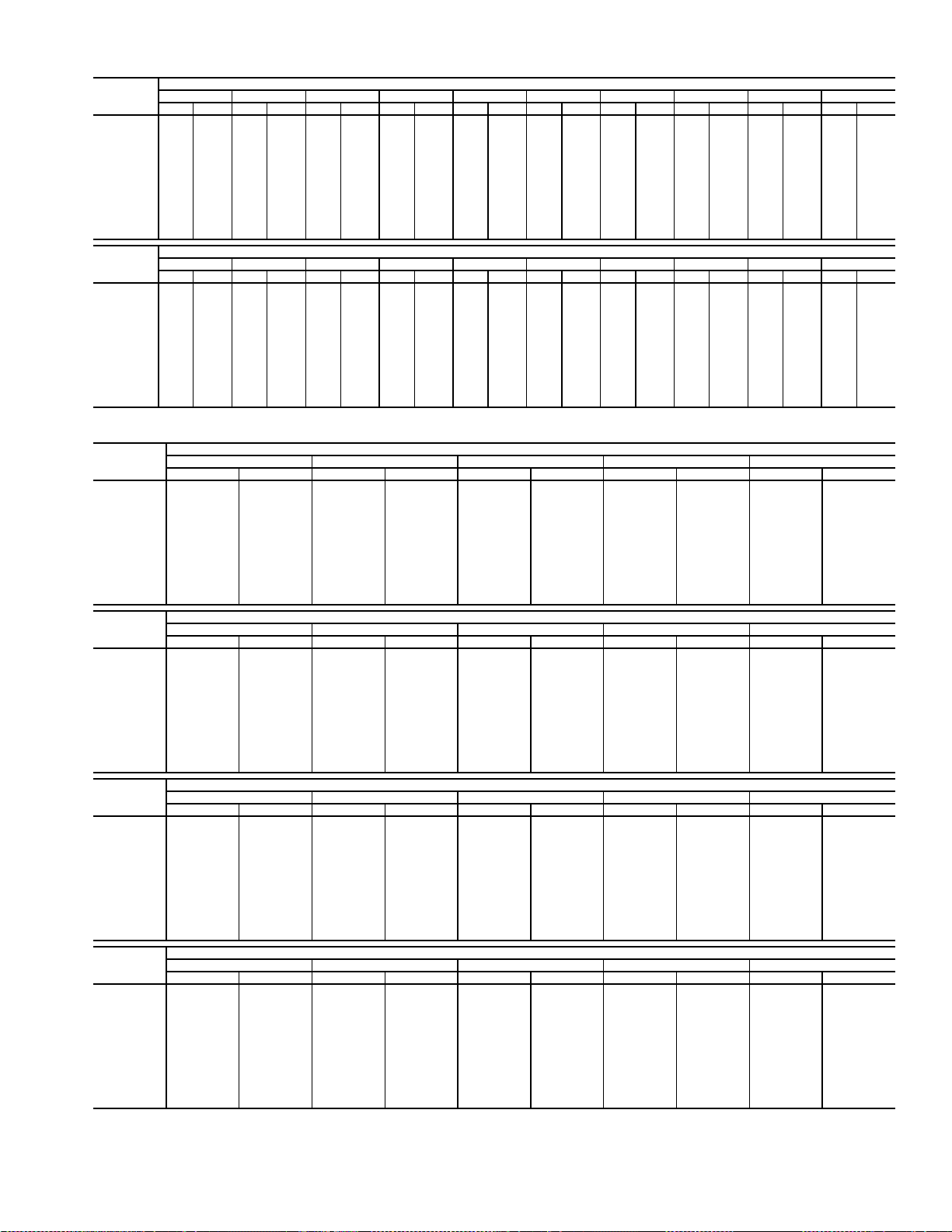
Table 25 — Fan Performance — 48AW,AY,A4,A5040 Units
AIRFLOW
(Cfm)
8,000 526 3.10 573 3.50 617 3.91 660 4.33 700 4.75 740 5.18 778 5.62 814 6.07 850 6.53 884 7.00
9,000 579 4.08 621 4.51 662 4.95 701 5.39 738 5.83 775 6.28 810 6.74 845 7.21 878 7.69 911 8.17
10,000 633 5.24 671 5.70 709 6.16 744 6.62 779 7.09 813 7.57 846 8.05 879 8.53 910 9.03 941 9.53
11,000 687 6.59 723 7.07 757 7.56 790 8.05 823 8.54 854 9.04 885 9.54 916 10.05 945 10.56 974 11.08
12,000 742 8.15 775 8.65 807 9.17 838 9.68 868 10.20 898 10.72 927 11.24 955 11.77 983 12.30 1011 12.84
13,000 797 9.92 827 10.45 857 10.98 887 11.52 915 12.07 943 12.61 970 13.15 997 13.70 1024 14.25 1050 14.81
14,000 852 11.92 881 12.47 909 13.03 936 13.59 963 14.15 990 14.72 1016 15.29 1041 15.86 1066 16.43 1091 17.01
15,000 908 1 4.15 935 14.72 961 15.31 987 15.89 1013 16.48 1038 17.06 1062 17.65 1086 18.25 1110 18.84 1134 19.44
16,000 964 16.63 989 17.23 1014 17.83 1039 18.43 1063 19.04 1086 19.65 1110 20.26 1133 20.88 1156 21.49 1178 22.11
17,000 1021 19.37 1044 19.98 1068 20.60 1091 21.23 1114 21.86 1136 22.49 1158 23.12 1180 23.76 1202 24.39 1223 25.03
18,000 1077 22.37 1099 23.01 1122 23.64 1144 24.29 1165 24.94 1187 25.59 1208 26.25 1229 26.90 1250 27.56 1270 28.22
19,000 113325.65115526.30117626.96119727.62121728.29123828.96————————
20,000 119029.21——————————————————
AIRFLOW
(Cfm)
8,000 917 7.48 949 7.96 980 8.44 1010 8.94 1039 9.43 1067 9.93 1094 10.44 1121 10.95 1147 11.46 1172 11.98
9,000 942 8.66 973 9.16 1003 9.66 1033 10.17 1061 10.69 1089 11.21 1116 11.73 1142 12.26 1168 12.80 1193 13.33
10,000 971 1 0.03 1001 10.55 1030 11.06 1058 11.59 1086 12.12 1113 12.66 1139 13.20 1165 13.75 1190 14.30 1215 14.86
11,000 1003 11.60 1031 12.13 1059 12.67 1086 13.21 1112 13.75 1139 14.31 1164 14.86 1189 15.43 1214 15.99 1238 16.56
12,000 1038 13.38 1065 13.92 1091 14.47 1117 15.03 1142 15.59 1167 16.16 1192 16.73 1216 17.31 1240 17.89 1264 18.48
13,000 1075 15.37 1101 15.93 1126 16.50 1150 17.07 1175 17.65 1199 18.23 1222 18.82 1246 19.41 1269 20.00 1291 20.61
14,000 1115 17.59 1139 18.17 1163 18.75 1186 19.34 1210 19.94 1232 20.53 1255 21.14 1277 21.74 1300 22.35 — —
15,000 115720.04118020.64120221.24122521.85124722.46126923.07129023.69——————
16,000 120022.73122223.35124323.97126524.60128625.23——————————
17,000 124525.67126626.32128626.96——————————————
18,000 129028.88——————————————————
19,000 ————————————————————
20,000 ————————————————————
0.20.40.60.81.01.21.41.61.82.0
Rpm Bhp Rpm Bhp Rpm Bhp Rpm Bhp Rpm Bhp Rpm Bhp Rpm Bhp Rpm Bhp Rpm Bhp Rpm Bhp
2.22.42.62.83.03.23.43.63.84.0
Rpm Bhp Rpm Bhp Rpm Bhp Rpm Bhp Rpm Bhp Rpm Bhp Rpm Bhp Rpm Bhp Rpm Bhp Rpm Bhp
AVAILABLE EXTERNAL STATIC PRESSURE (in. wg)
AVAILABLE EXTERNAL STATIC PRESSURE (in. wg)
Table 26 — Fan Performance — 48AW,AY041 Units
AIRFLOW
(Cfm)
8,000 526 3.10 573 3.50 617 3.91 660 4.33 700 4.75
9,000 579 4.08 621 4.51 662 4.95 701 5.39 738 5.83
10,000 633 5.24 671 5.70 709 6.16 744 6.62 779 7.09
11,000 687 6.59 723 7.07 757 7.56 790 8.05 823 8.54
12,000 742 8.15 775 8.65 807 9.17 838 9.68 868 10.20
13,000 797 9.92 827 10.45 857 10.98 887 11.52 915 12.07
14,000 852 11.92 881 12.47 909 13.03 936 13.59 963 14.15
15,000 908 14.15 935 14.72 961 15.31 987 15.89 1013 16.48
16,000 964 16.63 989 17.23 1014 17.83 1039 18.43 1063 19.04
17,000 1021 19.37 1044 19.98 1068 20.60 1091 21.23 1114 21.86
18,000 1077 22.37 1099 23.01 1122 23.64 1144 24.29 1165 24.94
19,000 1133 25.65 1155 26.30 1176 26.96 1197 27.62 1217 28.29
20,000 119029.21————————
AIRFLOW
(Cfm)
8,000 740 5.18 778 5.62 814 6.07 850 6.53 884 7.00
9,000 775 6.28 810 6.74 845 7.21 878 7.69 911 8.17
10,000 813 7.57 846 8.05 879 8.53 910 9.03 941 9.53
11,000 854 9.04 885 9.54 916 10.05 945 10.56 974 11.08
12,000 898 10.72 927 11.24 955 11.77 983 12.30 1011 12.84
13,000 943 12.61 970 13.15 997 13.70 1024 14.25 1050 14.81
14,000 990 14.72 1016 15.29 1041 15.86 1066 16.43 1091 17.01
15,000 1038 17.06 1062 17.65 1086 18.25 1110 18.84 1134 19.44
16,000 1086 19.65 1110 20.26 1133 20.88 1156 21.49 1178 22.11
17,000 1136 22.49 1158 23.12 1180 23.76 1202 24.39 1223 25.03
18,000 1187 25.59 1208 26.25 1229 26.90 1250 27.56 1270 28.22
19,000 123828.96————————
20,000 ——————————
AIRFLOW
(Cfm)
8,000 917 7.48 949 7.96 980 8.44 1010 8.94 1039 9.43
9,000 942 8.66 973 9.16 1003 9.66 1033 10.17 1061 10.69
10,000 971 10.03 1001 10.55 1030 11.06 1058 11.59 1086 12.12
11,000 1003 11.60 1031 12.13 1059 12.67 1086 13.21 1112 13.75
12,000 1038 13.38 1065 13.92 1091 14.47 1117 15.03 1142 15.59
13,000 1075 15.37 1101 15.93 1126 16.50 1150 17.07 1175 17.65
14,000 1115 17.59 1139 18.17 1163 18.75 1186 19.34 1210 19.94
15,000 1157 20.04 1180 20.64 1202 21.24 1225 21.85 1247 22.46
16,000 1200 22.73 1222 23.35 1243 23.97 1265 24.60 1286 25.23
17,000 1245 25.67 1266 26.32 1286 26.96 — — — —
18,000 129028.88————————
19,000 ——————————
20,000 ——————————
AIRFLOW
(Cfm)
8,000 1067 9.93 1094 10.44 1121 10.95 1147 11.46 1172 11.98
9,000 1089 11.21 1116 11.73 1142 12.26 1168 12.80 1193 13.33
10,000 1113 12.66 1139 13.20 1165 13.75 1190 14.30 1215 14.86
11,000 1139 14.31 1164 14.86 1189 15.43 1214 15.99 1238 16.56
12,000 1167 16.16 1192 16.73 1216 17.31 1240 17.89 1264 18.48
13,000 1199 18.23 1222 18.82 1246 19.41 1269 20.00 1291 20.61
14,000 1232 20.53 1255 21.14 1277 21.74 1300 22.35 — —
15,000 126923.07129023.69——————
16,000 ——————————
17,000 ——————————
18,000 ——————————
19,000 ——————————
20,000 ——————————
See legend on page 17.
0.2 0.4 0.6 0.8 1.0
Rpm Bhp Rpm Bhp Rpm Bhp Rpm Bhp Rpm Bhp
1.2 1.4 1.6 1.8 2.0
Rpm Bhp Rpm Bhp Rpm Bhp Rpm Bhp Rpm Bhp
2.2 2.4 2.6 2.8 3.0
Rpm Bhp Rpm Bhp Rpm Bhp Rpm Bhp Rpm Bhp
3.2 3.4 3.6 3.8 4.0
Rpm Bhp Rpm Bhp Rpm Bhp Rpm Bhp Rpm Bhp
AVAILABLE EXTERNAL STATIC PRESSURE (in. wg)
AVAILABLE EXTERNAL STATIC PRESSURE (in. wg)
AVAILABLE EXTERNAL STATIC PRESSURE (in. wg)
AVAILABLE EXTERNAL STATIC PRESSURE (in. wg)
19
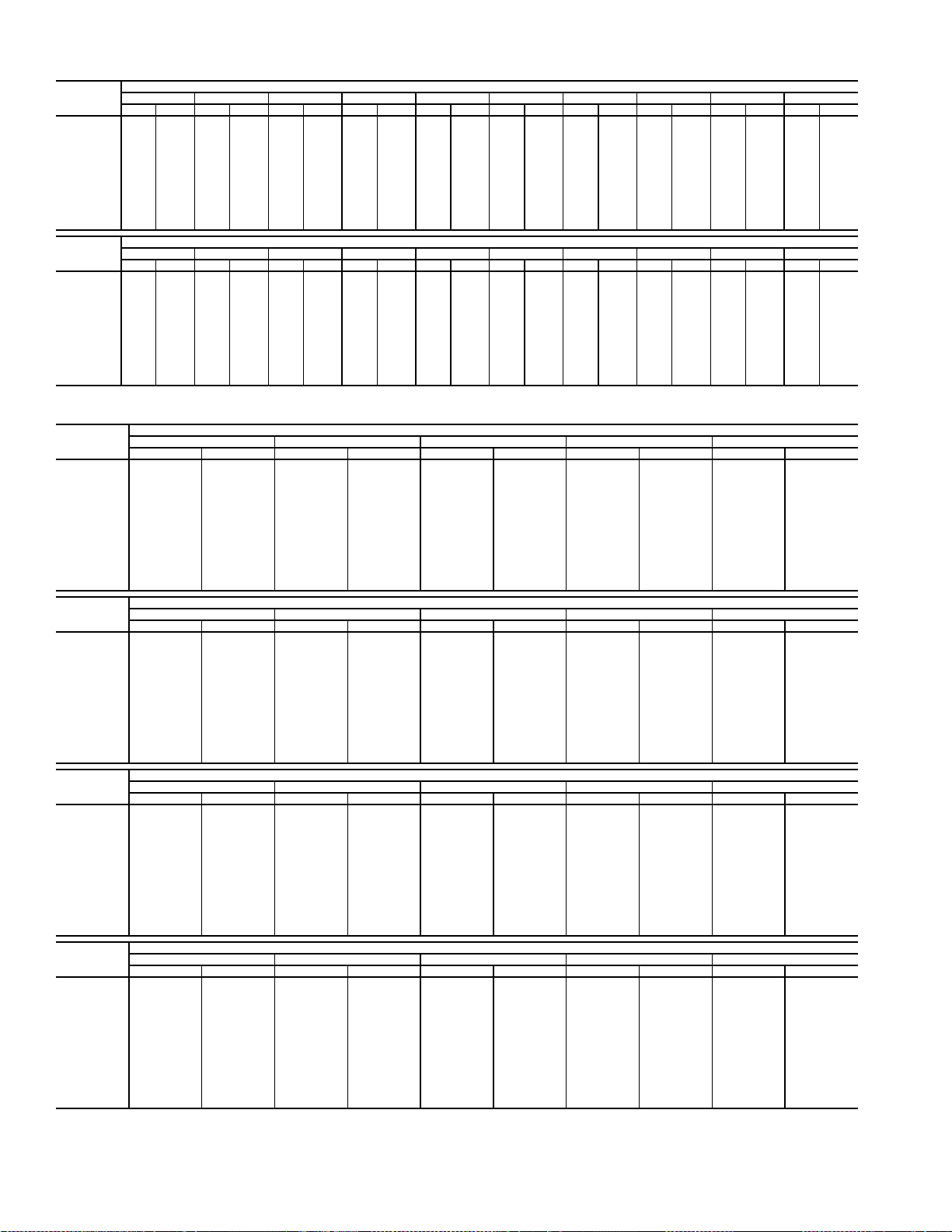
Table 27 — Fan Performance — 48AW,AY,A4,A5050 Units
AIRFLOW
(Cfm)
8,000 536 3.18 582 3.58 626 3.99 668 4.41 708 4.83 747 5.27 785 5.71 821 6.16 857 6.63 891 7.09
9,000 588 4.17 630 4.60 670 5.04 709 5.48 746 5.93 782 6.38 818 6.84 852 7.31 885 7.79 918 8.28
10,000 642 5.35 680 5.80 717 6.27 753 6.73 787 7.20 821 7.68 854 8.16 886 8.65 917 9.14 948 9.65
11,000 696 6.72 732 7.20 766 7.69 799 8.18 831 8.67 863 9.17 893 9.68 923 10.18 953 10.70 982 11.21
12,000 751 8.29 784 8.80 816 9.32 847 9.83 877 10.35 906 10.87 935 11.40 964 11.92 991 12.46 1019 12.99
13,000 807 10.09 837 10.62 867 11.16 896 11.70 924 12.24 952 12.78 979 13.33 1006 13.88 1032 14.43 1058 14.99
14,000 863 12.12 891 12.67 919 13.23 946 13.79 973 14.36 999 14.92 1025 15.49 1050 16.06 1075 16.64 1100 17.21
15,000 919 14.38 946 14.96 972 15.54 997 16.12 1023 16.71 1047 17.30 1072 17.89 1096 18.48 1120 19.08 1143 19.68
16,000 975 16.90 1000 17.49 1025 18.09 1049 18.70 1073 19.31 1097 19.92 1120 20.53 1143 21.15 1165 21.76 1188 22.38
17,000 1032 19.67 1056 20.29 1079 20.91 1102 21.54 1125 22.17 1147 22.80 1169 23.44 1191 24.07 1213 24.71 1234 25.35
18,000 1089 22.71 1111 23.35 1134 23.99 1155 24.64 1177 25.29 1198 25.95 1219 26.60 1240 27.26 1261 27.92 1281 28.58
19,000 1146 26.04 1167 26.69 1188 27.35 1209 28.02 1230 28.69 1250 29.37 1270 30.04 1290 30.72 ————
20,000 1203 29.65 1224 30.32 1244 31.00 1263 31.69 1283 32.38 ——————————
AIRFLOW
(Cfm)
8,000 923 7.57 955 8.05 986 8.54 1016 9.03 1045 9.53 1073 10.03 1100 10.54 1126 11.05 1152 11.56 1177 12.08
9,000 949 8.77 980 9.27 1010 9.77 1039 10.28 1067 10.80 1095 11.32 1122 11.85 1148 12.38 1174 12.91 1199 13.45
10,000 978 10.15 1008 10.67 1036 11.19 1064 11.72 1092 12.25 1119 12.79 1145 13.33 1171 13.88 1196 14.43 1221 14.99
11,000 1010 11.74 1038 12.27 1066 12.81 1093 13.35 1119 13.90 1145 14.45 1171 15.01 1196 15.57 1220 16.14 1245 16.72
12,000 1046 13.53 1072 14.08 1098 14.63 1124 15.19 1149 15.76 1174 16.32 1199 16.90 1223 17.48 1247 18.06 1270 18.65
13,000 1084 15.55 1109 16.11 1134 16.68 1158 17.26 1182 17.84 1206 18.42 1230 19.01 1253 19.60 1276 20.20 1299 20.80
14,000 1124 17.79 1148 18.38 1171 18.97 1195 19.55 1218 20.15 1241 20.75 1263 21.35 1285 21.96 ————
15,000 1166 20.27 1189 20.88 1211 21.49 1234 22.09 1256 22.71 1277 23.32 1299 23.94 — —————
16,000 1210 23.00 1231 23.62 1253 24.25 1274 24.88 1295 25.51 ——————————
17,000 1255 25.99 1276 26.63 1296 27.27 ——————————————
18,000 ————————————————————
19,000 ————————————————————
20,000 ————————————————————
0.2 0.4 0.6 0.8 1.0 1.2 1.4 1.6 1.8 2.0
Rpm Bhp Rpm Bhp Rpm Bhp Rpm Bhp Rpm Bhp Rpm Bhp Rpm Bhp Rpm Bhp Rpm Bhp Rpm Bhp
2.2 2.4 2.6 2.8 3.0 3.2 3.4 3.6 3.8 4.0
Rpm Bhp Rpm Bhp Rpm Bhp Rpm Bhp Rpm Bhp Rpm Bhp Rpm Bhp Rpm Bhp Rpm Bhp Rpm Bhp
AVAILABLE E XTERNAL STATIC PRESSURE (in. wg)
AVAILABLE E XTERNAL STATIC PRESSURE (in. wg)
Table 28 — Fan Performance — 48AW,AY051 Units
AIRFLOW
(Cfm)
10,000 450 3.19 509 3.86 561 4.58 608 5.34 651 6.14
12,000 516 4.81 569 5.54 617 6.30 660 7.10 701 7.93
13,000 550 5.80 600 6.56 646 7.34 688 8.15 727 9.00
14,000 584 6.90 632 7.69 676 8.50 716 9.33 754 10.20
15,000 619 8.13 664 8.96 706 9.79 745 10.65 782 11.53
16,000 654 9.49 697 10.36 737 11.22 775 12.10 811 13.00
17,000 689 10.99 730 11.90 769 12.79 806 13.69 840 14.61
18,000 725 12.64 764 13.58 801 14.51 837 15.43 870 16.38
19,000 760 14.43 798 15.41 834 16.37 868 17.32 900 18.29
20,000 796 16.37 833 17.39 867 18.39 900 19.37 931 20.36
21,000 832 18.47 867 19.54 901 20.56 932 21.57 963 22.59
22,000 869 20.74 902 21.84 934 22.90 965 23.94 995 24.98
23,000 905 23.17 937 24.31 968 25.40 998 26.48 1027 27.55
24,000 942 25.78 973 26.95 1003 28.08 1032 29.18 1059 30.28
25,000 978 28.56 1008 29.77 1037 30.93 1065 32.07 1092 33.20
AIRFLOW
(Cfm)
10,000 691 6.96 728 7.80 764 8.66 797 9.53 829 10.42
12,000 739 8.79 774 9.68 808 10.59 841 11.52 872 12.46
13,000 764 9.88 799 10.79 832 11.72 864 12.67 894 13.64
14,000 790 11.10 824 12.02 857 12.97 888 13.94 917 14.92
15,000 817 12.44 850 13.38 882 14.35 912 15.33 941 16.34
16,000 845 13.93 877 14.88 908 15.86 938 16.86 966 17.88
17,000 873 15.56 904 16.53 935 17.52 964 18.54 992 19.58
18,000 902 17.34 933 18.32 962 19.33 990 20.36 1018 21.41
19,000 932 19.27 961 20.27 990 21.29 1018 22.34 1045 23.40
20,000 962 21.36 991 22.38 1019 23.42 1046 24.48 1072 25.56
21,000 992 23.61 1020 24.65 1048 25.71 1074 26.78 1100 27.87
22,000 1023 26.03 1051 27.09 1077 28.17 1103 29.26 1129 30.36
23,000 1055 28.62 1081 29.70 1107 30.79 1133 31.90 1157 33.02
24,000 1086 31.38 1113 32.48 1138 33.59 1163 34.72 1187 35.86
25,000 1119 34.32 1144 35.44 1169 36.58 1193 37.72 — —
AIRFLOW
(Cfm)
10,000 860 11.31 890 12.21 918 13.11 946 14.02 973 14.94
12,000 901 13.42 930 14.38 958 15.36 985 16.34 1011 17.33
13,000 923 14.62 952 15.61 979 16.61 1006 17.62 1031 18.64
14,000 946 15.92 974 16.94 1001 17.97 1027 19.01 1052 20.06
15,000 970 17.36 997 18.40 1024 19.45 1049 20.51 1074 21.58
16,000 994 18.93 1021 19.98 1047 21.05 1072 22.14 1097 23.23
17,000 1019 20.63 1045 21.70 1071 22.79 1096 23.89 1120 25.01
18,000 1045 22.48 1070 23.57 1096 24.67 1120 25.79 1144 26.93
19,000 1071 24.49 1096 25.59 1121 26.71 1145 27.84 1169 28.99
20,000 1098 26.66 1123 27.77 1147 28.90 1171 30.05 1194 31.21
21,000 1125 28.99 1150 30.12 1173 31.26 1197 32.42 — —
22,000 1153 31.49 1177 32.63 ——————
23,000 118134.16————————
24,000 ——-————————
25,000 ———-———————
AIRFLOW
(Cfm)
10,000 998 15.86 1024 16.79 1048 17.72 1072 18.66 1096 19.60
12,000 1036 18.33 1061 19.33 1085 20.34 1108 21.35 1131 22.36
13,000 1056 19.67 1081 20.71 1104 21.75 1128 22.80 1150 23.85
14,000 1077 21.12 1101 22.18 1125 23.25 1148 24.33 1170 25.42
15,000 1099 22.67 1122 23.76 1146 24.86 1168 25.97 1191 27.08
16,000 1121 24.34 1144 25.45 1167 26.58 1190 27.71 — —
17,000 1144 26.13 1167 27.27 1190 28.42 — — — —
18,000 1167 28.07 1190 29.23 ——————
19,000 119230.16————————
20,000 ——————————
21,000 ——————————
22,000 ——————————
23,000 ——————————
24,000 ——————————
25,000 ——————————
0.2 0.4 0.6 0.8 1.0
Rpm Bhp Rpm Bhp Rpm Bhp Rpm Bhp Rpm Bhp
1.2 1.4 1.6 1.8 2.0
Rpm Bhp Rpm Bhp Rpm Bhp Rpm Bhp Rpm Bhp
2.2 2.4 2.6 2.8 3.0
Rpm Bhp Rpm Bhp Rpm Bhp Rpm Bhp Rpm Bhp
3.2 3.4 3.6 3.8 4.0
Rpm Bhp Rpm Bhp Rpm Bhp Rpm Bhp Rpm Bhp
AVAILABLE EXTERNAL STATIC PRESSURE (in. wg)
AVAILABLE EXTERNAL STATIC PRESSURE (in. wg)
AVAILABLE EXTERNAL STATIC PRESSURE (in. wg)
AVAILABLE EXTERNAL STATIC PRESSURE (in. wg)
20
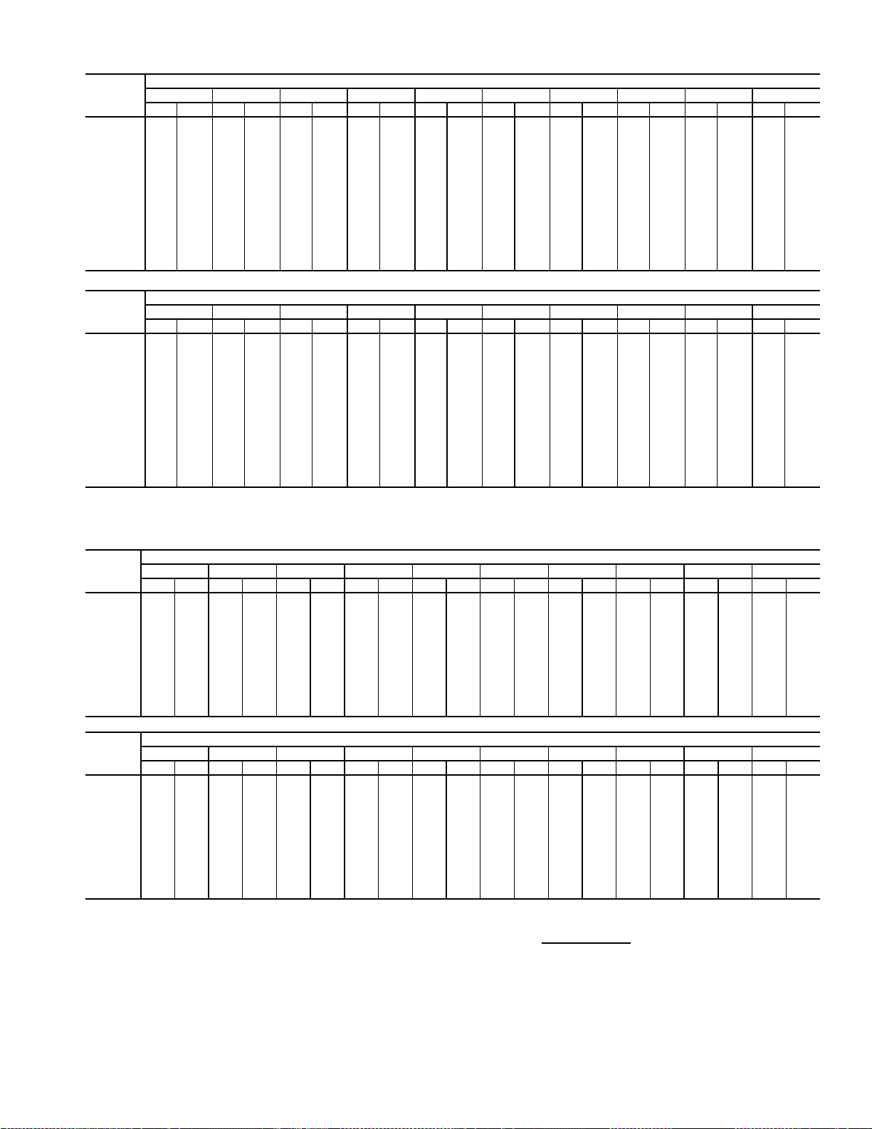
Table 29 — Fan Performance — 48AW,AY,A4,A5060 Units
AIRFLOW
(Cfm)
12,000 516 4.81 569 5.54 617 6.30 660 7.10 701 7.93 739 8.79 774 9.68 808 10.59 841 11.52 872 12.46
14,000 584 6.90 632 7.69 676 8.50 716 9.33 754 10.20 790 11.10 824 12.02 857 12.97 888 13.94 917 14.92
15,000 619 8.13 664 8.96 706 9.79 745 10.65 782 11.53 817 12.44 850 13.38 882 14.35 912 15.33 941 16.34
16,000 654 9.49 697 10.36 737 11.22 775 12.10 811 13.00 845 13.93 877 14.88 908 15.86 938 16.86 966 17.88
17,000 689 10.99 730 11.90 769 12.79 806 13.69 840 14.61 873 15.56 904 16.53 935 17.52 964 18.54 992 19.58
18,000 725 12.64 764 13.58 801 14.51 837 15.43 870 16.38 902 17.34 933 18.32 962 19.33 990 20.36 1018 21.41
19,000 760 14.43 798 15.41 834 16.37 868 17.32 900 18.29 932 19.27 961 20.27 990 21.29 1018 22.34 1045 23.40
20,000 796 16.37 833 17.39 867 18.39 900 19.37 931 20.36 962 21.36 991 22.38 1019 23.42 1046 24.48 1072 25.56
21,000 832 18.47 867 19.54 901 20.56 932 21.57 963 22.59 992 23.61 1020 24.65 1048 25.71 1074 26.78 1100 27.87
22,000 869 20.74 902 21.84 934 22.90 965 23.94 995 24.98 1023 26.03 1051 27.09 1077 28.17 1103 29.26 1129 30.36
23,000 905 23.17 937 24.31 968 25.40 998 26.48 1027 27.55 1055 28.62 1081 29.70 1107 30.79 1133 31.90 1157 33.02
24,000 942 25.78 973 26.95 1003 28.08 1032 29.18 1059 30.28 1086 31.38 1113 32.48 1138 33.59 1163 34.72 1187 35.86
25,000 978 28.56 1008 29.77 1037 30.93 1065 32.07 1092 33.20 1119 34.32 1144 35.44 1169 36.58 1193 37.72 — —
26,000 1015 31.52 1044 32.76 1072 33.96 1099 35.13 1125 36.29 1151 37.44 1176 38.59 — — — — — —
27,000 1052 34.66 1080 35.94 1107 37.18 1133 38.38 1159 39.57 1184 40.75 ————————
0.2 0.4 0.6 0.8 1.0 1.2 1.4 1.6 1.8 2.0
Rpm Bhp Rpm Bhp Rpm Bhp Rpm Bhp Rpm Bhp Rpm Bhp Rpm Bhp Rpm Bhp Rpm Bhp Rpm Bhp
AVAILABLE EXTERNAL STATIC PRESSURE (in. wg)
AIRFLOW
(Cfm)
12,000 901 13.42 930 14.38 958 15.36 985 16.34 1011 17.33 1036 18.33 1061 19.33 1085 20.34 1108 21.35 1131 22.36
14,000 946 15.92 974 16.94 1001 17.97 1027 19.01 1052 20.06 1077 21.12 1101 22.18 1125 23.25 1148 24.33 1170 25.42
15,000 970 17.36 997 18.40 1024 19.45 1049 20.51 1074 21.58 1099 22.67 1122 23.76 1146 24.86 1168 25.97 1191 27.08
16,000 994 18.93 1021 19.98 1047 21.05 1072 22.14 1097 23.23 1121 24.34 1144 25.45 1167 26.58 1190 27.71 — —
17,000 1019 20.63 1045 21.70 1071 22.79 1096 23.89 1120 25.01 1144 26.13 1167 27.27 1190 28.42 — — — —
18,000 1045 22.48 1070 23.57 1096 24.67 1120 25.79 1144 26.93 1167 28.07 1190 29.23 — — — — — —
19,000 1071 24.49 1096 25.59 1121 26.71 1145 27.84 1169 28.99 1192 30.16 ————————
20,000 1098 26.66 1123 27.77 1147 28.90 1171 30.05 1194 31.21 — — ————————
21,000 112528.99115030.12117331.26119732.42————————————
22,000 115331.49117732.63————————————————
23,000 118134.16——————————————————
24,000 ————————————————————
25,000 ————————————————————
26,000 ————————————————————
27,000 ————————————————————
2.2 2.4 2.6 2.8 3.0 3.2 3.4 3.6 3.8 4.0
Rpm Bhp Rpm Bhp Rpm Bhp Rpm Bhp Rpm Bhp Rpm Bhp Rpm Bhp Rpm Bhp Rpm Bhp Rpm Bhp
AVAILABLE EXTERNAL STATIC PRESSURE (in. wg)
Table 30 — Fan Performance — 50AW,AY020,025 and 50A4,A5020 Units
AIRFLOW
(CFM)
4,000 322 0.62 399 0.82 464 1.04 521 1.26 572 1.48 619 1.71 662 1.93 702 2.16 739 2.38 774 2.61
5,000 361 0.95 431 1.17 491 1.41 545 1.65 594 1.89 640 2.14 682 2.39 722 2.64 759 2.89 795 3.14
6,000 405 1.41 467 1.64 524 1.88 574 2.14 621 2.40 664 2.67 705 2.93 744 3.20 780 3.47 816 3.75
7,000 451 2.00 508 2.22 559 2.48 607 2.75 651 3.02 693 3.30 732 3.58 769 3.87 804 4.16 839 4.45
7,500 475 2.34 529 2.57 579 2.82 625 3.10 668 3.38 708 3.66 746 3.96 783 4.25 818 4.55 851 4.84
8,000 500 2.72 551 2.95 598 3.21 643 3.48 685 3.77 724 4.06 762 4.36 797 4.66 832 4.96 864 5.27
9,000 550 3.60 596 3.83 640 4.09 682 4.36 721 4.66 759 4.96 795 5.27 829 5.58 862 5.90 893 6.22
10,000 601 4.63 644 4.86 684 5.12 723 5.40 760 5.70 796 6.01 830 6.33 863 6.65 894 6.98 925 7.31
11,000 653 5.83 692 6.07 730 6.33 766 6.61 801 6.91 835 7.22 867 7.54 899 7.87 929 8.21 958 8.55
12,000 706 7.20 742 7.45 777 7.71 811 7.99 844 8.29 875 8.61 906 8.93 936 9.27 966 9.61 994 9.96
12,500 732 7.96 768 8.20 801 8.47 834 8.75 866 9.05 897 9.37 927 9.69 956 10.03 985 10.38 1012 10.73
13,000 759 8.76 793 9.01 826 9.27 857 9.56 888 9.86 918 10.17 947 10.50 976 10.84 1004 11.19 1031 11.54
0.2 0.4 0.6 0.8 1.0 1.2 1.4 1.6 1.8 2.0
Rpm Bhp Rpm Bhp Rpm Bhp Rpm Bhp Rpm Bhp Rpm Bhp Rpm Bhp Rpm Bhp Rpm Bhp Rpm Bhp
AVAILABLE EXTERNAL STATIC PRESSURE (in. wg)
AIRFLOW
(CFM)
4,000 808 2.84 840 3.06 870 3.29 900 3.52 928 3.75 955 3.98 981 4.21 1007 4.44 1031 4.67 1055 4.91
5,000 829 3.39 861 3.64 892 3.89 922 4.14 950 4.40 978 4.65 1005 4.90 1031 5.16 1056 5.41 1080 5.67
6,000 849 4.02 881 4.29 912 4.57 942 4.84 971 5.12 999 5.39 1026 5.67 1052 5.94 1077 6.22 1102 6.49
7,000 871 4.74 903 5.03 933 5.33 963 5.62 991 5.92 1019 6.21 1046 6.51 1072 6.80 1098 7.10 1123 7.40
7,500 883 5.14 915 5.44 945 5.75 974 6.05 1002 6.35 1030 6.66 1057 6.96 1083 7.27 1108 7.58 1133 7.88
8,000 896 5.58 927 5.89 957 6.20 985 6.51 1014 6.82 1041 7.13 1067 7.45 1093 7.76 1118 8.08 1143 8.39
9,000 924 6.54 954 6.86 983 7.19 1011 7.51 1038 7.84 1064 8.17 1090 8.50 1116 8.83 1141 9.16 1165 9.49
10,000 954 7.64 983 7.98 1011 8.31 1038 8.65 1065 8.99 1091 9.34 1116 9.68 1141 10.02 1165 10.37 1189 10.72
11,000 987 8.89 1015 9.24 1042 9.59 1068 9.94 1094 10.29 1119 10.65 1144 11.01 1168 11.36 1191 11.72 — —
12,000 1022 10.31 1048 10.67 1075 11.03 1100 11.39 1125 11.75 1150 12.12 1173 12.48 1197 12.85 — — — —
12,500 1039 11.08 1066 11.44 1092 11.81 1117 12.17 1141 12.54 1165 12.91 1189 13.28 — — — — — —
13,000 1058 11.90 1084 12.26 1109 12.63 1134 13.00 1158 13.37 1182 13.75 — — — — — — — —
LEGEND
Bhp — Brake Horsepower
edb — Entering Dry Bulb
ewb — Entering Wet Bulb
NOTES:
1. Fan performance is based on wet coils, economizer, roof curb, cabinet
losses, and clean 2-in. filters.
2.2 2.4 2.6 2.8 3.0 3.2 3.4 3.6 3.8 4.0
Rpm Bhp Rpm Bhp Rpm Bhp Rpm Bhp Rpm Bhp Rpm Bhp Rpm Bhp Rpm Bhp Rpm Bhp Rpm Bhp
AVAILABLE EXTERNAL STATIC PRESSURE (in. wg)
2. Conversion — Bhp to watts:
Watts =
3. Variable air volume units will operate down to 70 cfm/ton. Performance at
70 cfm/ton is limited to unloaded operation and may be additionally limited
by edb and ewb conditions.
Bhp x 746
Motor efficiency
21
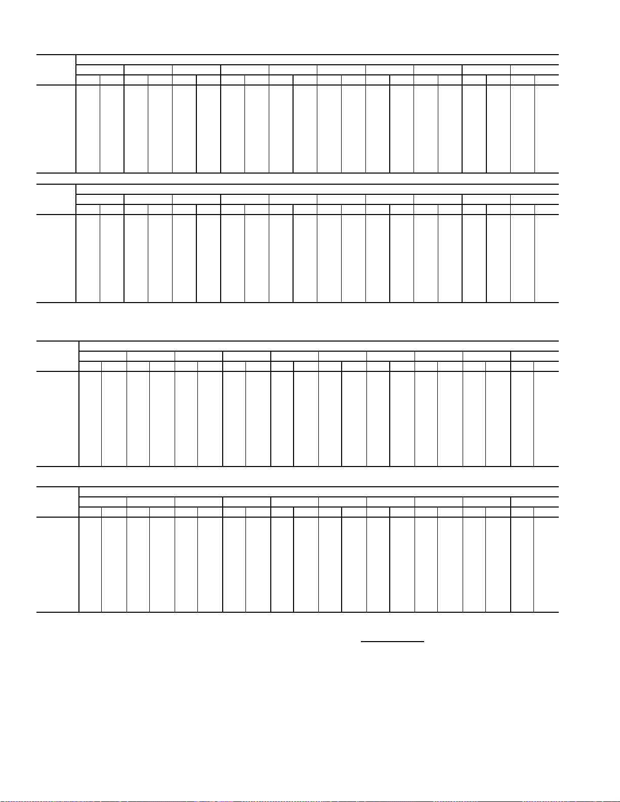
Table 31 — Fan Performance — 50AW,AY027,030 and 50A4,A5025-030 Units
AIRFLOW
(CFM)
4,000 325 0.62 402 0.83 466 1.05 523 1.27 574 1.49 620 1.72 663 1.94 703 2.17 740 2.39 776 2.62
5,000 366 0.97 435 1.19 495 1.42 548 1.67 597 1.91 642 2.16 685 2.41 724 2.65 762 2.90 797 3.16
6,000 411 1.43 473 1.66 529 1.91 579 2.16 625 2.43 668 2.69 709 2.96 747 3.23 784 3.50 819 3.77
7,000 459 2.02 515 2.25 566 2.51 613 2.78 657 3.06 698 3.34 737 3.62 774 3.91 809 4.20 843 4.49
8,000 508 2.76 559 2.99 606 3.25 650 3.53 691 3.82 731 4.11 768 4.41 803 4.71 837 5.01 870 5.32
9,000 560 3.64 605 3.88 649 4.14 690 4.42 729 4.72 766 5.02 802 5.33 835 5.64 868 5.96 900 6.28
10,000 612 4.68 654 4.92 694 5.19 732 5.47 769 5.77 804 6.09 838 6.40 870 6.73 902 7.06 932 7.39
11,000 665 5.89 703 6.14 740 6.41 776 6.69 811 7.00 844 7.31 876 7.64 907 7.97 937 8.31 967 8.65
12,000 718 7.28 754 7.53 788 7.80 822 8.09 854 8.39 886 8.71 916 9.04 946 9.38 975 9.72 1003 10.07
13,000 772 8.85 806 9.11 838 9.38 869 9.67 899 9.98 929 10.30 958 10.63 987 10.97 1014 11.32 1041 11.68
14,000 826 10.61 858 10.87 888 11.15 917 11.44 946 11.75 974 12.07 1002 12.41 1029 12.75 1055 13.10 1081 13.46
15,000 881 12.57 910 12.84 939 13.12 967 13.41 994 13.72 1021 14.05 1047 14.38 1073 14.73 1098 15.08 1123 15.45
AIRFLOW
(CFM)
4,000 809 2.84 841 3.07 872 3.30 901 3.53 929 3.76 956 3.99 982 4.22 1008 4.45 1032 4.68 1056 4.92
5,000 831 3.41 863 3.66 894 3.91 924 4.16 952 4.41 980 4.67 1007 4.92 1032 5.17 1057 5.43 1082 5.68
6,000 852 4.05 884 4.32 915 4.59 945 4.87 974 5.14 1001 5.42 1028 5.69 1054 5.97 1080 6.24 1105 6.52
7,000 875 4.78 907 5.07 937 5.37 967 5.66 995 5.95 1023 6.25 1049 6.55 1076 6.84 1101 7.14 1126 7.44
8,000 901 5.63 932 5.94 961 6.25 990 6.56 1018 6.87 1045 7.18 1072 7.50 1097 7.81 1123 8.13 1147 8.44
9,000 930 6.60 960 6.93 988 7.25 1016 7.58 1043 7.91 1070 8.23 1096 8.57 1121 8.90 1146 9.23 1170 9.56
10,000 961 7.72 990 8.06 1018 8.40 1045 8.74 1071 9.08 1097 9.42 1122 9.76 1147 10.11 1171 10.46 1194 10.80
11,000 995 8.99 1022 9.34 1049 9.69 1075 10.04 1101 10.39 1126 10.75 1151 11.11 1175 11.47 1198 11.82 — —
12,000 1030 10.43 1057 10.78 1083 11.14 1108 11.51 1133 11.87 1157 12.24 1181 12.61 — — — — — —
13,000 1068 12.04 1093 12.40 1119 12.77 1143 13.14 1167 13.52 1191 13.89 — — — — — — — —
14,000 1107 13.83 1131 14.20 1156 14.58 1179 14.96 ————————————
15,000 1147 15.82 1171 16.19 1194 16.58 — — ————————————
0.2 0.4 0.6 0.8 1.0 1.2 1.4 1.6 1.8 2.0
Rpm Bhp Rpm Bhp Rpm Bhp Rpm Bhp Rpm Bhp Rpm Bhp Rpm Bhp Rpm Bhp Rpm Bhp Rpm Bhp
2.2 2.4 2.6 2.8 3.0 3.2 3.4 3.6 3.8 4.0
Rpm Bhp Rpm Bhp Rpm Bhp Rpm Bhp Rpm Bhp Rpm Bhp Rpm Bhp Rpm Bhp Rpm Bhp Rpm Bhp
AVAILABLE EXTERNAL STATIC PRESSURE (in. wg)
AVAILABLE EXTERNAL STATIC PRESSURE (in. wg)
Table 32 — Fan Performance — 50AW,AY,A4,A5035 Units
AIRFLOW
(Cfm)
7,000 522 2.06 573 2.32 620 2.57 664 2.82 705 3.06 744 3.30 780 3.54 815 3.78 849 4.01 881 4.24
8,000 576 2.75 622 3.03 665 3.30 706 3.57 745 3.84 782 4.10 817 4.36 850 4.62 883 4.87 914 5.12
9,000 630 3.57 672 3.86 712 4.16 750 4.45 787 4.74 822 5.02 855 5.30 888 5.58 919 5.86 949 6.13
10,000 686 4.52 724 4.84 761 5.15 797 5.46 831 5.77 864 6.07 896 6.37 927 6.67 957 6.97 986 7.26
10,500 714 5.05 750 5.38 786 5.70 821 6.02 854 6.34 886 6.65 917 6.96 947 7.27 977 7.57 1005 7.87
11,000 742 5.62 777 5.95 811 6.28 845 6.61 877 6.94 909 7.26 939 7.58 968 7.90 997 8.21 1025 8.52
12,000 799 6.88 831 7.22 863 7.57 894 7.91 925 8.25 954 8.60 983 8.93 1011 9.27 1039 9.60 1065 9.93
13,000 856 8.29 886 8.65 916 9.01 945 9.37 974 9.72 1002 10.08 1029 10.44 1056 10.79 1082 11.14 1108 11.49
14,000 914 9.87 942 10.24 969 10.61 997 10.98 1024 11.36 1050 11.73 1076 12.10 1102 12.47 1127 12.84 1152 13.20
15,000 971 11.62 998 12.00 1024 12.39 1050 12.77 1075 13.16 1100 13.54 1125 13.93 1149 14.31 1173 14.70 1197 15.08
16,000 1029 13.55 1054 13.94 1079 14.34 1103 14.74 1127 15.13 1151 15.53 1174 15.93 1198 16.33 1220 16.73 1243 17.12
17,000 1088 15.66 1111 16.07 1134 16.47 1157 16.88 1180 17.29 1203 17.70 1225 18.11 1247 18.53 1269 18.93 1290 19.34
17,500 1117 16.79 1140 17.20 1162 17.61 1184 18.02 1207 18.44 1229 18.86 1250 19.27 1272 19.69 1293 20.11 — —
0.2 0.4 0.6 0.8 1.0 1.2 1.4 1.6 1.8 2.0
Rpm Bhp Rpm Bhp Rpm Bhp Rpm Bhp Rpm Bhp Rpm Bhp Rpm Bhp Rpm Bhp Rpm Bhp Rpm Bhp
AVAILABLE EXTERNAL STATIC PRESSURE (in. wg)
AIRFLOW
(Cfm)
7,000 912 4.46 942 4.68 970 4.90 998 5.12 1025 5.33 1051 5.54 1076 5.75 1101 5.96 1124 6.16 1148 6.36
8,000 944 5.37 973 5.62 1001 5.86 1029 6.11 1055 6.35 1081 6.58 1106 6.82 1130 7.05 1154 7.28 1177 7.51
9,000 978 6.40 1006 6.67 1034 6.93 1060 7.20 1086 7.46 1112 7.72 1136 7.98 1160 8.23 1184 8.49 1207 8.74
10,000 1014 7.55 1041 7.84 1068 8.12 1094 8.41 1119 8.69 1144 8.97 1168 9.25 1192 9.52 1215 9.80 1238 10.07
10,500 1033 8.17 1059 8.47 1086 8.77 1111 9.06 1136 9.35 1161 9.64 1184 9.93 1208 10.22 1231 10.50 1253 10.79
11,000 1052 8.83 1078 9.14 1104 9.44 1129 9.75 1154 10.05 1178 10.35 1201 10.64 1224 10.94 1247 11.23 1269 11.53
12,000 1091 10.26 1117 10.58 1142 10.90 1166 11.23 1190 11.54 1213 11.86 1236 12.18 1259 12.49 1281 12.80 — —
13,000 1133 11.83 1157 12.17 1181 12.51 1205 12.85 1228 13.19 1251 13.52 1273 13.86 1295 14.19 — — — —
14,000 1176 13.56 1199 13.92 1222 14.28 1245 14.63 1268 14.99 1290 15.34 — ———————
15,000 122015.45124315.83126516.20128716.58————————————
16,000 126517.52128717.91————————————————
17,000 ————————————————————
17,500 ————————————————————
LEGEND
Bhp — Brake Horsepower
edb — Entering Dry Bulb
ewb — Entering Wet Bulb
NOTES:
1. Fan performance is based on wet coils, economizer, roof curb, cabinet
losses, and clean 2-in. filters.
2.2 2.4 2.6 2.8 3.0 3.2 3.4 3.6 3.8 4.0
Rpm Bhp Rpm Bhp Rpm Bhp Rpm Bhp Rpm Bhp Rpm Bhp Rpm Bhp Rpm Bhp Rpm Bhp Rpm Bhp
AVAILABLE EXTERNAL STATIC PRESSURE (in. wg)
2. Conversion — Bhp to watts:
Watts =
3. Variable air volume units will operate down to 70 cfm/ton. Performance at
70 cfm/ton is limited to unloaded operation and may be additionally limited
by edb and ewb conditions.
Bhp x 746
Motor efficiency
22
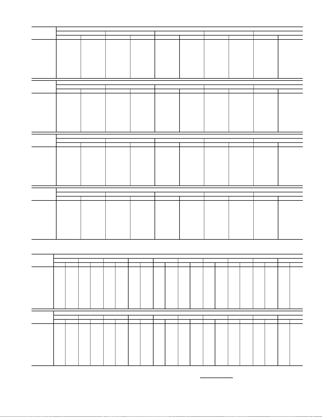
Table 33 — Fan Performance — 50AW,AY036 Units
AIRFLOW
(Cfm)
7,000 451 2.13 503 2.49 552 2.86 597 3.23 641 3.60
8,000 499 2.88 546 3.27 590 3.66 632 4.06 672 4.46
9,000 548 3.78 591 4.20 631 4.62 670 5.04 708 5.47
10,000 599 4.86 637 5.30 675 5.74 711 6.19 746 6.64
11,000 649 6.11 685 6.57 720 7.04 753 7.51 786 7.99
12,000 701 7.54 734 8.03 766 8.52 797 9.02 828 9.52
13,000 753 9.18 783 9.69 813 10.21 842 10.72 871 11.25
14,000 805 11.03 833 11.56 861 12.09 889 12.63 916 13.18
15,000 857 13.09 884 13.64 910 14.20 936 14.76 962 15.32
16,000 910 15.38 935 15.95 960 16.53 984 17.11 1008 17.69
17,000 963 17.91 986 18.50 1010 19.09 1033 19.69 1056 20.30
17,500 989 19.26 1012 19.86 1035 20.47 1058 21.08 1080 21.69
AIRFLOW
(Cfm)
7,000 682 3.99 722 4.39 760 4.80 797 5.22 832 5.65
8,000 711 4.87 748 5.28 784 5.70 819 6.14 853 6.58
9,000 744 5.90 778 6.33 812 6.77 845 7.22 877 7.67
10,000 779 7.09 812 7.55 844 8.01 875 8.47 905 8.94
11,000 817 8.47 848 8.94 878 9.43 907 9.91 936 10.40
12,000 857 10.02 886 10.52 915 11.03 943 11.53 970 12.04
13,000 899 11.77 927 12.30 953 12.82 980 13.35 1006 13.88
14,000 942 13.73 968 14.27 994 14.82 1019 15.37 1044 15.92
15,000 987 15.89 1011 16.46 1036 17.03 1060 17.61 1083 18.18
16,000 1032 18.28 1056 18.87 1079 19.47 1101 20.06 1124 20.66
17,000 1078 20.91 1101 21.52 1123 22.13 1145 22.75 1166 23.36
17,500 1102 22.31 1124 22.93 1145 23.55 1166 24.18 1187 24.80
AIRFLOW
(Cfm)
7,000 866 6.09 899 6.54 931 6.99 961 7.45 991 7.91
8,000 885 7.03 917 7.48 948 7.95 978 8.42 1007 8.90
9,000 908 8.13 939 8.60 968 9.08 997 9.56 1026 10.05
10,000 934 9.42 963 9.90 992 10.39 1020 10.89 1047 11.39
11,000 964 10.89 992 11.39 1019 11.89 1045 12.40 1071 12.91
12,000 996 12.55 1023 13.07 1048 13.59 1074 14.11 1099 14.64
13,000 1031 14.41 1056 14.95 1081 15.48 1105 16.03 1129 16.57
14,000 1068 16.48 1092 17.03 1115 17.59 1138 18.15 1161 18.71
15,000 1106 18.75 1129 19.33 1151 19.91 1174 20.48 1196 21.07
16,000 1146 21.25 1168 21.85 1189 22.45 1211 23.04 1232 23.64
17,000 1187 23.98 1208 24.60 1229 25.21 1249 25.83 1270 26.46
17,500 1208 25.43 1229 26.06 1249 26.69 1269 27.32 1289 27.95
AIRFLOW
(Cfm)
7,000 1020 8.39 1047 8.86 1074 9.34 1101 9.83 1126 10.32
8,000 1036 9.39 1063 9.88 1090 10.38 1116 10.88 1142 11.39
9,000 1053 10.55 1080 11.05 1107 11.56 1133 12.08 1158 12.60
10,000 1073 11.89 1100 12.41 1125 12.93 1151 13.45 1175 13.99
11,000 1097 13.43 1122 13.96 1147 14.49 1171 15.02 1195 15.56
12,000 1123 15.17 1147 15.71 1171 16.25 1195 16.80 1218 17.35
13,000 1152 17.12 1175 17.67 1198 18.22 1221 18.78 1243 19.35
14,000 1184 19.27 1206 19.84 1228 20.41 1250 20.99 1271 21.56
15,000 1217 21.65 1239 22.23 1260 22.82 1280 23.41 — —
16,000 1253 24.25 1273 24.85 1293 25.45 — — — —
17,000 128927.07————————
17,500 ——————————
0.2 0.4 0.6 0.8 1.0
Rpm Bhp Rpm Bhp Rpm Bhp Rpm Bhp Rpm Bhp
1.2 1.4 1.6 1.8 2.0
Rpm Bhp Rpm Bhp Rpm Bhp Rpm Bhp Rpm Bhp
2.2 2.4 2.6 2.8 3.0
Rpm Bhp Rpm Bhp Rpm Bhp Rpm Bhp Rpm Bhp
3.2 3.4 3.6 3.8 4.0
Rpm Bhp Rpm Bhp Rpm Bhp Rpm Bhp Rpm Bhp
AVAILABLE EXTERNAL STATIC PRESSURE (in. wg)
AVAILABLE EXTERNAL STATIC PRESSURE (in. wg)
AVAILABLE EXTERNAL STATIC PRESSURE (in. wg)
AVAILABLE EXTERNAL STATIC PRESSURE (in. wg)
Table 34 — Fan Performance — 50AW,AY,A4,A5040 Units
AIRFLOW
(Cfm)
8,000 499 2.88 546 3.27 590 3.66 632 4.06 672 4.46 711 4.87 748 5.28 784 5.70 819 6.14 853 6.58
9,000 548 3.78 591 4.20 631 4.62 670 5.04 708 5.47 744 5.90 778 6.33 812 6.77 845 7.22 877 7.67
10,000 599 4.86 637 5.30 675 5.74 711 6.19 746 6.64 779 7.09 812 7.55 844 8.01 875 8.47 905 8.94
11,000 649 6.11 685 6.57 720 7.04 753 7.51 786 7.99 817 8.47 848 8.94 878 9.43 907 9.91 936 10.40
12,000 701 7.54 734 8.03 766 8.52 797 9.02 828 9.52 857 10.02 886 10.52 915 11.03 943 11.53 970 12.04
13,000 753 9.18 783 9.69 813 10.21 842 10.72 871 11.25 899 11.77 927 12.30 953 12.82 980 13.35 1006 13.88
14,000 805 11.03 833 11.56 861 12.09 889 12.63 916 13.18 942 13.73 968 14.27 994 14.82 1019 15.37 1044 15.92
15,000 857 13.09 884 13.64 910 14.20 936 14.76 962 15.32 987 15.89 1011 16.46 1036 17.03 1060 17.61 1083 18.18
16,000 910 1 5.38 935 15.95 960 16.53 984 17.11 1008 17.69 1032 18.28 1056 18.87 1079 19.47 1101 20.06 1124 20.66
17,000 963 17.91 986 18.50 1010 19.09 1033 19.69 1056 20.30 1078 20.91 1101 21.52 1123 22.13 1145 22.75 1166 23.36
18,000 1016 20.68 1038 21.29 1060 21.90 1082 22.52 1104 23.15 1126 23.77 1147 24.41 1168 25.04 1189 25.67 1209 26.31
19,000 1069 23.71 1090 24.33 1111 24.96 1132 25.60 1153 26.25 1173 26.89 1194 27.54 1214 28.19 1234 28.85 — —
20,000 112226.99114227.64116228.29118228.95————————————
AIRFLOW
(Cfm)
8,000 885 7.03 917 7.48 948 7.95 978 8.42 1007 8.90 1036 9.39 1063 9.88 1090 10.38 1116 10.88 1142 11.39
9,000 908 8.13 939 8.60 968 9.08 997 9.56 1026 10.05 1053 10.55 1080 11.05 1107 11.56 1133 12.08 1158 12.60
10,000 934 9.42 963 9.90 992 10.39 1020 10.89 1047 11.39 1073 11.89 1100 12.41 1125 12.93 11 51 13.45 1175 13.99
11,000 964 10.89 992 11.39 1019 11.89 1045 12.40 1071 12.91 1097 13.43 1122 13.96 1147 14.49 1171 15.02 1195 15.56
12,000 996 1 2.55 1023 13.07 1048 13.59 1074 14.11 1099 14.64 1123 15.17 1147 15.71 1171 16.25 1195 16.80 1218 17.35
13,000 1031 14.41 1056 14.95 1081 15.48 1105 16.03 1129 16.57 1152 17.12 1175 17.67 1198 18.22 1221 18.78 1243 19.35
14,000 1068 16.48 1092 17.03 1115 17.59 1138 18.15 1161 18.71 1184 19.27 1206 19.84 1228 20.41 1250 20.99 1271 21.56
15,000 1106 18.75 1129 19.33 1151 19.91 1174 20.48 1196 21.07 1217 21.65 1239 22.23 1260 22.82 1280 23.41 — —
16,000 114621.25116821.85118922.45121123.04123223.64125324.25127324.85129325.45————
17,000 118723.98120824.60122925.21124925.83127026.46128927.07————————
18,000 123026.95125027.58126928.22128928.86————————————
19,000 ————————————————————
20,000 ————————————————————
LEGEND
Bhp — Brake Horsepower
edb — Entering Dry Bulb
ewb — Entering Wet Bulb
NOTES:
1. Fan performance is based on wet coils, economizer, roof curb, cabinet losses, and clean
2-in. filters.
0.20.40.60.81.01.21.41.61.82.0
Rpm Bhp Rpm Bhp Rpm Bhp Rpm Bhp Rpm Bhp Rpm Bhp Rpm Bhp Rpm Bhp Rpm Bhp Rpm Bhp
2.22.42.62.83.03.23.43.63.84.0
Rpm Bhp Rpm Bhp Rpm Bhp Rpm Bhp Rpm Bhp Rpm Bhp Rpm Bhp Rpm Bhp Rpm Bhp Rpm Bhp
AVAILABLE EXTERNAL STATIC PRESSURE (in. wg)
AVAILABLE EXTERNAL STATIC PRESSURE (in. wg)
2. Conversion — Bhp to watts:
Watts =
3. Variable air volume units will operate down to 70 cfm/ton. Performance at 70 cfm/ton is
limited to unloaded operation and may be additional limited by edb and ewb conditions.
Bhp x 746
Motor efficiency
23
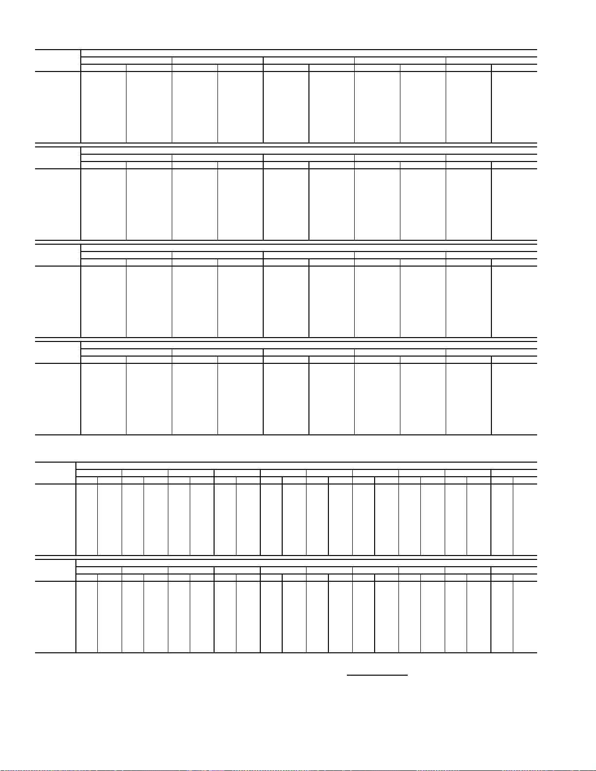
Table 35 — Fan Performance — 50AW,AY041 Units
AIRFLOW
(Cfm)
8,000 499 2.88 546 3.27 590 3.66 632 4.06 672 4.46
9,000 548 3.78 591 4.20 631 4.62 670 5.04 708 5.47
10,000 599 4.86 637 5.30 675 5.74 711 6.19 746 6.64
11,000 649 6.11 685 6.57 720 7.04 753 7.51 786 7.99
12,000 701 7.54 734 8.03 766 8.52 797 9.02 828 9.52
13,000 753 9.18 783 9.69 813 10.21 842 10.72 871 11.25
14,000 805 11.03 833 11.56 861 12.09 889 12.63 916 13.18
15,000 857 13.09 884 13.64 910 14.20 936 14.76 962 15.32
16,000 910 15.38 935 15.95 960 16.53 984 17.11 1008 17.69
17,000 963 17.91 986 18.50 1010 19.09 1033 19.69 1056 20.30
18,000 1016 20.68 1038 21.29 1060 21.90 1082 22.52 1104 23.15
19,000 1069 23.71 1090 24.33 1111 24.96 1132 25.60 1153 26.25
20,000 1122 26.99 1142 27.64 1162 28.29 1182 28.95 — —
AIRFLOW
(Cfm)
8,000 711 4.87 748 5.28 784 5.70 819 6.14 853 6.58
9,000 744 5.90 778 6.33 812 6.77 845 7.22 877 7.67
10,000 779 7.09 812 7.55 844 8.01 875 8.47 905 8.94
11,000 817 8.47 848 8.94 878 9.43 907 9.91 936 10.40
12,000 857 10.02 886 10.52 915 11.03 943 11.53 970 12.04
13,000 899 11.77 927 12.30 953 12.82 980 13.35 1006 13.88
14,000 942 13.73 968 14.27 994 14.82 1019 15.37 1044 15.92
15,000 987 15.89 1011 16.46 1036 17.03 1060 17.61 1083 18.18
16,000 1032 18.28 1056 18.87 1079 19.47 1101 20.06 1124 20.66
17,000 1078 20.91 1101 21.52 1123 22.13 1145 22.75 1166 23.36
18,000 1126 23.77 1147 24.41 1168 25.04 1189 25.67 1209 26.31
19,000 1173 26.89 1194 27.54 1214 28.19 1234 28.85 — —
20,000 ——————————
AIRFLOW
(Cfm)
8,000 885 7.03 917 7.48 948 7.95 978 8.42 1007 8.90
9,000 908 8.13 939 8.60 968 9.08 997 9.56 1026 10.05
10,000 934 9.42 963 9.90 992 10.39 1020 10.89 1047 11.39
11,000 964 10.89 992 11.39 1019 11.89 1045 12.40 1071 12.91
12,000 996 12.55 1023 13.07 1048 13.59 1074 14.11 1099 14.64
13,000 1031 14.41 1056 14.95 1081 15.48 1105 16.03 1129 16.57
14,000 1068 16.48 1092 17.03 1115 17.59 1138 18.15 1161 18.71
15,000 1106 18.75 1129 19.33 1151 19.91 1174 20.48 1196 21.07
16,000 1146 21.25 1168 21.85 1189 22.45 1211 23.04 1232 23.64
17,000 1187 23.98 1208 24.60 1229 25.21 1249 25.83 1270 26.46
18,000 1230 26.95 1250 27.58 1269 28.22 1289 28.86 — —
19,000 ——————————
20,000 ——————————
AIRFLOW
(Cfm)
8,000 1036 9.39 1063 9.88 1090 10.38 1116 10.88 1142 11.39
9,000 1053 10.55 1080 11.05 1107 11.56 1133 12.08 1158 12.60
10,000 1073 11.89 1100 12.41 1125 12.93 1151 13.45 1175 13.99
11,000 1097 13.43 1122 13.96 1147 14.49 1171 15.02 1195 15.56
12,000 1123 15.17 1147 15.71 1171 16.25 1195 16.80 1218 17.35
13,000 1152 17.12 1175 17.67 1198 18.22 1221 18.78 1243 19.35
14,000 1184 19.27 1206 19.84 1228 20.41 1250 20.99 1271 21.56
15,000 1217 21.65 1239 22.23 1260 22.82 1280 23.41 — —
16,000 1253 24.25 1273 24.85 1293 25.45 — — — —
17,000 128927.07————————
18,000 ——————————
19,000 ——————————
20,000 ——————————
0.2 0.4 0.6 0.8 1.0
Rpm Bhp Rpm Bhp Rpm Bhp Rpm Bhp Rpm Bhp
1.2 1.4 1.6 1.8 2.0
Rpm Bhp Rpm Bhp Rpm Bhp Rpm Bhp Rpm Bhp
2.2 2.4 2.6 2.8 3.0
Rpm Bhp Rpm Bhp Rpm Bhp Rpm Bhp Rpm Bhp
3.2 3.4 3.6 3.8 4.0
Rpm Bhp Rpm Bhp Rpm Bhp Rpm Bhp Rpm Bhp
AVAILABLE EXTERNAL STATIC PRESSURE (in. wg)
AVAILABLE EXTERNAL STATIC PRESSURE (in. wg)
AVAILABLE EXTERNAL STATIC PRESSURE (in. wg)
AVAILABLE EXTERNAL STATIC PRESSURE (in. wg)
Table 36 — Fan Performance — 50AW,AY,A4,A5050 Units
AIRFLOW
(Cfm)
8,000 509 2.95 555 3.35 599 3.74 640 4.14 680 4.54 718 4.95 755 5.36 791 5.79 826 6.22 859 6.66
9,000 558 3.87 600 4.29 640 4.71 678 5.13 715 5.56 751 5.99 786 6.42 819 6.87 852 7.31 884 7.77
10,000 608 4.96 646 5.40 683 5.85 719 6.30 754 6.75 787 7.20 819 7.66 851 8.12 882 8.58 912 9.06
11,000 659 6.23 694 6.69 728 7.16 762 7.64 794 8.11 825 8.59 856 9.07 886 9.55 915 10.04 943 10.53
12,000 710 7.68 743 8.17 775 8.67 806 9.17 836 9.67 866 10.17 895 10.67 923 11.17 950 11.68 978 12.19
13,000 763 9.35 793 9.86 823 10.37 852 10.89 880 11.42 908 11.94 935 12.47 962 12.99 988 13.52 1014 14.05
14,000 815 11.22 843 11.75 871 12.29 899 12.83 925 13.38 952 13.92 978 14.47 1003 15.02 1028 15.57 1052 16.12
15,000 868 13.31 895 13.86 921 14.42 946 14.98 972 15.55 997 16.12 1021 16.69 1045 17.26 1069 17.83 1092 18.41
16,000 921 15.64 946 16.21 971 16.78 995 17.37 1019 17.96 1043 18.54 1066 19.14 1089 19.73 1111 20.32 1134 20.92
17,000 974 18.20 998 18.79 1021 19.39 1044 19.99 1067 20.60 1089 21.21 1112 21.82 1134 22.43 1155 23.05 1176 23.66
18,000 1028 21.01 1050 21.62 1072 22.24 1094 22.86 1116 23.49 1137 24.12 1158 24.75 1179 25.38 1200 26.02 1220 26.65
19,000 1081 24.08 1103 24.71 1124 25.35 1145 25.99 1165 26.63 1185 27.28 1206 27.93 1226 28.58 1245 29.24 1265 29.90
20,000 1135 27.42 1155 28.06 1175 28.72 1195 29.38 1215 30.04 1234 30.71 1254 31.38 1273 32.05 1292 32.72 — —
AIRFLOW
(Cfm)
8,000 892 7.12 923 7.57 954 8.04 984 8.52 1013 9.00 1041 9.49 1069 9.98 1095 10.48 1121 10.98 1147 11.49
9,000 915 8.23 945 8.70 975 9.18 1003 9.67 1032 10.16 1059 10.66 1086 11.16 1112 11.67 1138 12.19 1163 12.71
10,000 941 9.53 970 10.02 998 10.51 1026 11.00 1053 11.51 1080 12.01 1106 12.53 1131 13.05 1156 13.58 1181 14.11
11,000 971 11.02 999 11.52 1026 12.02 1052 12.53 1078 13.05 1103 13.57 1128 14.09 1153 14.63 1177 15.16 1201 15.71
12,000 1004 12.70 1030 13.22 1056 13.74 1081 14.26 1106 14.79 1130 15.33 1154 15.86 1178 16.41 1201 16.96 1224 17.51
13,000 1039 14.59 1064 15.12 1088 15.66 1113 16.20 1136 16.74 1160 17.29 1183 17.85 1206 18.40 1228 18.96 1250 19.53
14,000 1076 16.68 1100 17.23 1123 17.79 1147 18.35 1169 18.91 1192 19.48 1214 20.04 1236 20.62 1257 21.19 1279 21.77
15,000 1115 18.98 1138 19.56 1160 20.14 1182 20.72 1204 21.30 1226 21.88 1247 22.47 1268 23.05 1289 23.65 — —
16,000 1156 21.52 1178 22.11 1199 22.71 1220 23.31 1241 23.91 1262 24.51 1282 25.12 — —————
17,000 1198 24.28 1218 24.90 1239 25.52 1259 26.14 1279 26.76 1299 27.38 — — — —————
18,000 1240 27.29 1260 27.93 1280 28.57 1300 29.21 — — ——————————
19,000 1284 30.55 — — — ———————————————
20,000 ————————————————————
LEGEND
Bhp — Brake Horsepower
edb — Entering Dry Bulb
ewb — Entering Wet Bulb
NOTES:
1. Fan performance is based on wet coils, economizer, roof curb, cabinet losses, and clean 2-in.
filters.
0.2 0.4 0.6 0.8 1.0 1.2 1.4 1.6 1.8 2.0
Rpm Bhp Rpm Bhp Rpm Bhp Rpm Bhp Rpm Bhp Rpm Bhp Rpm Bhp Rpm Bhp Rpm Bhp Rpm Bhp
2.2 2.4 2.6 2.8 3.0 3.2 3.4 3.6 3.8 4.0
Rpm Bhp Rpm Bhp Rpm Bhp Rpm Bhp Rpm Bhp Rpm Bhp Rpm Bhp Rpm Bhp Rpm Bhp Rpm Bhp
AVAILABLE E XTERNAL STATIC PRESSURE (in. wg)
AVAILABLE E XTERNAL STATIC PRESSURE (in. wg)
2. Conversion — Bhp to watts:
Watts =
3. Variable air volume units will operate down to 70 cfm/ton. Performance at 70 cfm/ton is limited to
unloaded operation and may be additionally limited by edb and ewb conditions.
Motor efficiency
Bhp x 746
24
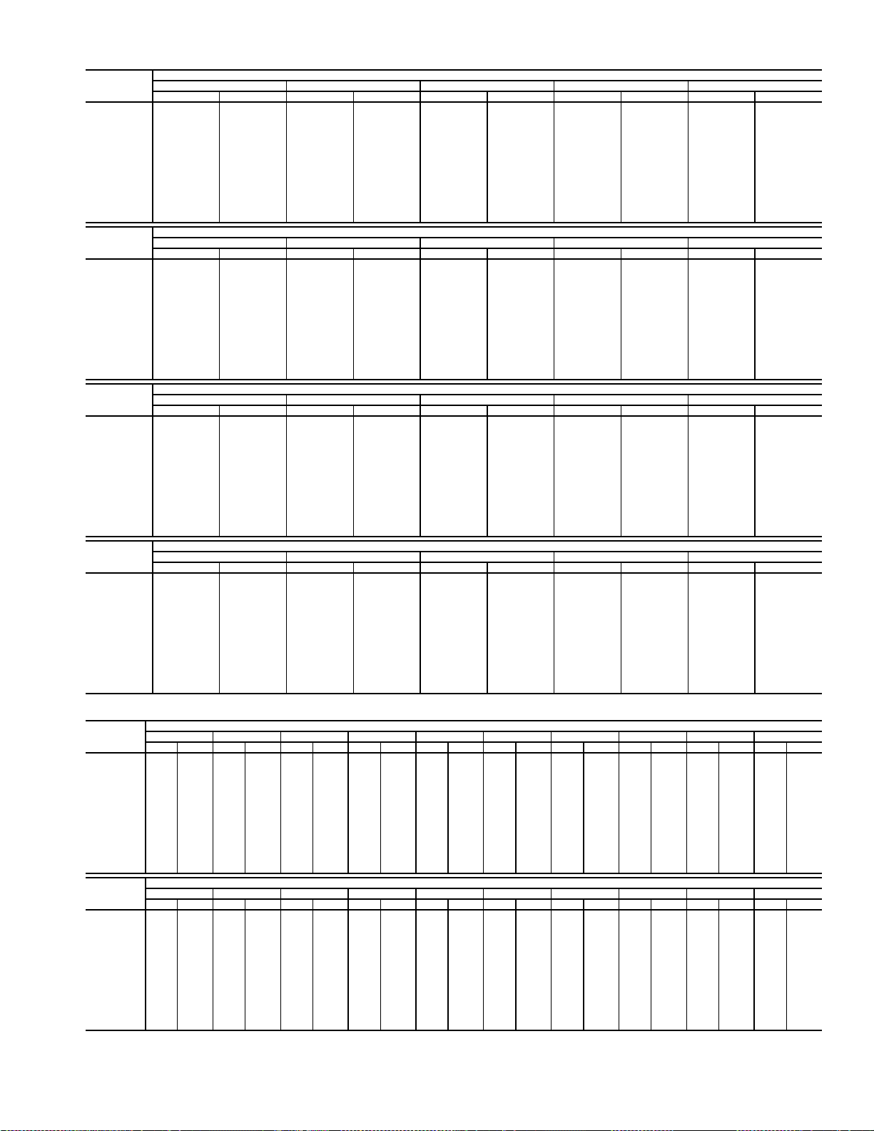
Table 37 — Fan Performance — 50AW,AY051 Units
AIRFLOW
(Cfm)
10,000 429 2.98 488 3.61 539 4.26 585 4.95 627 5.66
12,000 490 4.48 543 5.17 591 5.88 634 6.61 673 7.36
13,000 522 5.39 572 6.11 618 6.85 659 7.61 698 8.38
14,000 554 6.41 602 7.17 645 7.94 686 8.72 723 9.51
15,000 586 7.56 632 8.34 674 9.14 713 9.94 749 10.77
16,000 619 8.83 663 9.64 703 10.46 741 11.30 776 12.14
17,000 652 10.23 694 11.07 733 11.92 769 12.78 803 13.65
18,000 685 11.76 725 12.63 763 13.51 798 14.39 831 15.29
19,000 719 13.44 757 14.33 793 15.23 827 16.14 860 17.07
20,000 753 15.26 789 16.18 824 17.10 857 18.04 888 18.99
21,000 787 17.23 822 18.17 855 19.12 887 20.08 918 21.05
22,000 821 19.35 855 20.32 887 21.29 918 22.28 947 23.28
23,000 855 21.63 888 22.62 919 23.62 949 24.63 977 25.65
24,000 889 24.07 921 25.08 951 26.11 980 27.14 1008 28.19
25,000 924 26.67 954 27.71 983 28.76 1011 29.82 1038 30.89
AIRFLOW
(Cfm)
10,000 666 6.41 703 7.17 737 7.96 770 8.78 801 9.61
12,000 711 8.14 746 8.94 779 9.76 811 10.60 841 11.45
13,000 734 9.18 769 9.99 801 10.82 832 11.68 862 12.55
14,000 759 10.33 792 11.16 824 12.01 855 12.88 884 13.76
15,000 784 11.60 816 12.45 848 13.32 878 14.21 906 15.11
16,000 810 13.00 841 13.87 872 14.76 901 15.66 929 16.58
17,000 836 14.53 867 15.42 897 16.33 926 17.25 953 18.19
18,000 863 16.20 893 17.11 922 18.04 950 18.98 978 19.93
19,000 890 18.00 920 18.94 949 19.88 976 20.84 1003 21.81
20,000 918 19.94 947 20.90 975 21.87 1002 22.85 1028 23.84
21,000 947 22.03 975 23.02 1002 24.01 1029 25.01 1054 26.02
22,000 976 24.28 1003 25.28 1030 26.30 1056 27.32 1081 28.35
23,000 1005 26.68 1032 27.71 1058 28.75 1083 29.79 1108 30.85
24,000 1035 29.24 1061 30.29 1086 31.35 1111 32.42 1135 33.49
25,000 1065 31.96 1090 33.04 1115 34.12 1139 35.21 1163 36.31
AIRFLOW
(Cfm)
10,000 831 10.46 860 11.33 888 12.21 915 13.11 941 14.02
12,000 870 12.33 898 13.22 925 14.13 951 15.06 977 16.00
13,000 891 13.44 918 14.35 945 15.27 971 16.20 996 17.16
14,000 912 14.67 939 15.59 965 16.52 991 17.47 1016 18.44
15,000 934 16.02 961 16.96 987 17.90 1012 18.87 1036 19.84
16,000 957 17.51 983 18.46 1008 19.42 1033 20.39 1057 21.38
17,000 980 19.13 1006 20.10 1031 21.07 1055 22.06 1079 23.06
18,000 1004 20.89 1029 21.87 1054 22.86 1078 23.86 1101 24.88
19,000 1028 22.80 1053 23.79 1078 24.80 1101 25.81 1124 26.84
20,000 1053 24.85 1078 25.86 1102 26.88 1125 27.91 1148 28.96
21,000 1079 27.04 1103 28.07 1126 29.11 1149 30.16 1172 31.22
22,000 1105 29.39 1129 30.44 1152 31.50 1174 32.57 1196 33.65
23,000 1131 31.90 1155 32.97 1177 34.05 1199 35.13 — —
24,000 1158 34.57 1181 35.66 ——————
25,000 118637.41————————
AIRFLOW
(Cfm)
10,000 966 14.94 991 15.88 1014 16.83 1038 17.79 1060 18.76
12,000 1002 16.96 1026 17.92 1049 18.90 1072 19.89 1094 20.89
13,000 1020 18.13 1044 19.11 1067 20.10 1090 21.10 1112 22.12
14,000 1040 19.42 1063 20.41 1086 21.41 1109 22.43 1131 23.46
15,000 1060 20.83 1083 21.84 1106 22.85 1128 23.88 1150 24.92
16,000 1081 22.39 1104 23.40 1126 24.43 1148 25.47 1170 26.52
17,000 1102 24.07 1125 25.10 1147 26.14 1169 27.19 1190 28.26
18,000 1124 25.91 1147 26.94 1169 28.00 1190 29.06 — —
19,000 1147 27.89 1169 28.94 1190 30.00 — — — —
20,000 1170 30.01 1192 31.08 ——————
21,000 119432.30————————
22,000 ——————————
23,000 ——————————
24,000 ——————————
25,000 ——————————
0.2 0.4 0.6 0.8 1.0
Rpm Bhp Rpm Bhp Rpm Bhp Rpm Bhp Rpm Bhp
1.2 1.4 1.6 1.8 2.0
Rpm Bhp Rpm Bhp Rpm Bhp Rpm Bhp Rpm Bhp
2.2 2.4 2.6 2.8 3.0
Rpm Bhp Rpm Bhp Rpm Bhp Rpm Bhp Rpm Bhp
3.2 3.4 3.6 3.8 4.0
Rpm Bhp Rpm Bhp Rpm Bhp Rpm Bhp Rpm Bhp
AVAILABLE EXTERNAL STATIC PRESSURE (in. wg)
AVAILABLE EXTERNAL STATIC PRESSURE (in. wg)
AVAILABLE EXTERNAL STATIC PRESSURE (in. wg)
AVAILABLE EXTERNAL STATIC PRESSURE (in. wg)
Table 38 — Fan Performance — 50AW,AY,A4,A5060 Units
AIRFLOW
(Cfm)
12,000 490 4.48 543 5.17 591 5.88 634 6.61 674 7.37 711 8.14 746 8.94 779 9.76 811 10.60 841 11.45
14,000 554 6.41 602 7.17 645 7.94 686 8.72 723 9.51 759 10.33 792 11.16 824 12.01 855 12.88 884 13.76
15,000 586 7.56 632 8.34 674 9.14 713 9.94 749 10.77 784 11.60 816 12.45 848 13.32 878 14.21 906 15.11
16,000 619 8.83 663 9.64 703 10.46 741 11.30 776 12.14 810 13.00 841 13.87 872 14.76 901 15.66 929 16.58
17,000 652 10.23 694 11.07 733 11.92 769 12.78 803 13.65 836 14.53 867 15.42 897 16.33 926 17.25 953 18.19
18,000 685 11.76 725 12.63 763 13.51 798 14.39 831 15.29 863 16.20 893 17.11 922 18.04 950 18.98 978 19.93
19,000 719 13.44 757 14.33 793 15.23 827 16.14 860 17.07 890 18.00 920 18.94 949 19.88 976 20.84 1003 21.81
20,000 753 15.26 789 16.18 824 17.10 857 18.04 888 18.99 918 19.94 947 20.90 975 21.87 1002 22.85 1028 23.84
21,000 787 17.23 822 18.17 855 19.12 887 20.08 918 21.05 947 22.03 975 23.02 1002 24.01 1029 25.01 1054 26.02
22,000 821 19.35 855 20.32 887 21.29 918 22.28 947 23.28 976 24.28 1003 25.28 1030 26.30 1056 27.32 1081 28.35
23,000 855 21.63 888 22.62 919 23.62 949 24.63 977 25.65 1005 26.68 1032 27.71 1058 28.75 1083 29.79 1108 30.85
24,000 889 24.07 921 25.08 951 26.11 980 27.14 1008 28.19 1035 29.24 1061 30.29 1086 31.35 1111 32.42 1135 33.49
25,000 924 26.67 954 27.71 983 28.76 1011 29.82 1038 30.89 1065 31.96 1090 33.04 1115 34.12 1139 35.21 1163 36.31
26,000 958 29.45 987 30.51 1016 31.59 1043 32.67 1069 33.76 1095 34.85 1120 35.95 1144 37.06 1168 38.17 1191 39.29
27,000 993 32.40 1021 33.49 1048 34.58 1075 35.69 1101 36.80 1126 37.92 1150 39.04 1174 40.17 1197 41.30 — —
AIRFLOW
(Cfm)
12,000 870 12.33 898 13.22 925 14.13 951 15.06 977 16.00 1002 16.96 1026 17.92 1049 18.90 1072 19.89 1094 20.89
14,000 912 14.67 939 15.59 965 16.52 991 17.47 1016 18.44 1040 19.42 1063 20.41 1086 21.41 1109 22.43 1131 23.46
15,000 934 16.02 961 16.96 987 17.90 1012 18.87 1036 19.84 1060 20.83 1083 21.84 1106 22.85 1128 23.88 1150 24.92
16,000 957 17.51 983 18.46 1008 19.42 1033 20.39 1057 21.38 1081 22.39 1104 23.40 1126 24.43 1148 25.47 1170 26.52
17,000 980 19.13 1006 20.10 1031 21.07 1055 22.06 1079 23.06 1102 24.07 1125 25.10 1147 26.14 1169 27.19 1190 28.26
18,000 1004 20.89 1029 21.87 1054 22.86 1078 23.86 1101 24.88 1124 25.91 1147 26.94 1169 28.00 1190 29.06 — —
19,000 1028 22.80 1053 23.79 1078 24.80 1101 25.81 1124 26.84 1147 27.89 1169 28.94 1190 30.00 — — — —
20,000 1053 24.85 1078 25.86 1102 26.88 1125 27.91 1148 28.96 1170 30.01 1192 31.08 — — — — — —
21,000 1079 27.04 1103 28.07 1126 29.11 1149 30.16 1172 31.22 1194 32.30 — — — — — — — —
22,000 1105 29.39 1129 30.44 1152 31.50 1174 32.57 1196 33.65 ——————————
23,000 1131 31.90 1155 32.97 1177 34.05 1199 35.13 — — ——————————
24,000 1158 34.57 1181 35.66 — ———————————————
25,000 1186 37.41 — — — ———————————————
26,000 ————————————————————
27,000 ————————————————————
0.2 0.4 0.6 0.8 1.0 1.2 1.4 1.6 1.8 2.0
RpmBhpRpmBhpRpmBhpRpmBhpRpmBhpRpmBhpRpmBhpRpmBhpRpmBhpRpmBhp
2.2 2.4 2.6 2.8 3.0 3.2 3.4 3.6 3.8 4.0
RpmBhpRpmBhpRpmBhpRpmBhpRpmBhpRpmBhpRpmBhpRpmBhpRpmBhpRpmBhp
AVAILABLE E XTERNAL STATIC PRESSURE (in. wg)
AVAILABLE E XTERNAL STATIC PRESSURE (in. wg)
25
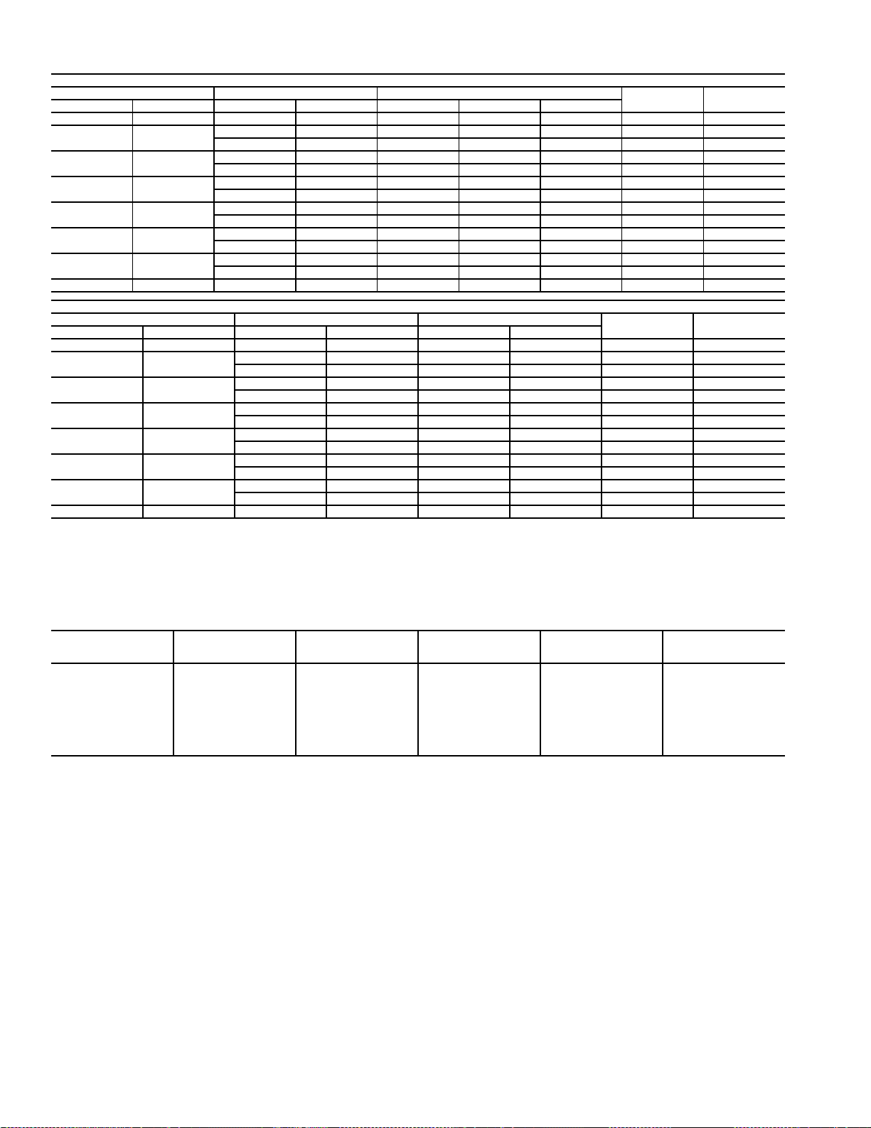
Table 39 — Motor Limitations
Nominal Maximum Maximum Amps
Bhp BkW Bhp BkW 230 v 460 v 575 v
53.735.9 4.40 15.0 7.9 6.0 5,030 87.5
7.5 5.6
10 7.46
15 11.19
20 14.92
25 18.65
30 22.38
40 29.84 42.0 31.33 110.0 55.0 43.8 33,690 93.0
Nominal Maximum Maximum Amps
Bhp BkW Bhp BkW 230 v 460 v
53.735.9 4.40 15.8 7.9 4,918 89.5
7.5 5.6
10 7.46
15 11.19
20 14.92
25 18.65
30 22.38
40 29.84 42.0 31.33 110.0 55.0 33,156 94.5
LEGEND
Bhp — Brake Horsepower
BkW — Brake Kilowatts
NOTES:
1. Extensive motor and electrical testing on the Carrier units has ensured that
the full horsepower range of the motor can be utilized with confidence.
8.7 6.49 23.5 — — 7,717 84.1
9.5 7.09 — 12.0 10.0 8,008 88.5
10.2 7.61 31.0 — — 9,502 89.5
11.8 8.80 — 15.0 12.0 9,836 89.5
15.3 11.41 46.0 — — 12,543 91.0
18.0 13.43 — 22.0 19.0 14,756 91.0
22.4 16.71 60.0 — — 18,363 91.0
23.4 17.46 — 28.7 23.0 19,183 91.0
28.9 21.56 73.0 — — 23,511 91.7
29.4 21.93 — 37.4 28.4 23,918 91.7
35.6 26.56 91.0 — — 28,742 92.4
34.7 25.89 — 43.8 36.3 28,015 92.4
8.7 6.49 23.5 — 7,078 91.7
9.5 7.09 — 12.0 7,728 91.7
10.2 7.61 30.0 — 8,298 91.0
11.8 8.80 — 15.0 9,600 91.7
15.3 11.41 46.0 — 12,273 91.7
18.0 13.43 — 22.0 14,439 93.0
22.4 16.71 59.0 — 17,853 93.0
23.4 17.46 — 28.7 18,650 93.6
28.9 21.56 73.0 — 23,034 93.6
29.4 21.93 — 36.3 23,432 93.6
35.6 26.56 82.6 — 28,374 93.6
34.7 25.89 — 41.7 27,656 93.6
HIGH-EFFICIENCY MOTORS
PREMIUM-EFFICIENCY MOTORS
Using the fan motors up to the horsepower ratings shown in the Motor Limitations table will not result in nuisance tripping or premature motor failures. Unit warranty will not be affected.
2. All motors comply with Energy Policy Act (EPACT) Standards effective
October 24, 1997.
Maximum
Watts
Maximum
Watts
Maximum
Efficiency
Maximum
Efficiency
Table 40A — Air Quantity Limits (48AJ,AK,AW,AY,A2,A3,A4,A5)
UNIT SIZE*
020 5,900 6,100 4,000 6,000 10,000
025 5,900 6,100 5,000 7,500 12,500
027 5,900 6,100 5,400 8,100 13,500
030 5,900 6,100 6,000 9,000 15,000
035 (AJ,AK,AW,AY) 5,900 6,100 7,000 10,500 17,500
035 (A2,A3,A4,A5) 5,900 10,100 7,000 10,500 17,500
036,040,041 7,600 10,100 8,000 12,000 20,000
050 7,600 10,100 10,000 15,000 22,500
051,060 11,000 10,100 12,000 18,000 27,000
LEGEND
CV — Constant Volume
VAV — Variable Air Volume
MINIMUM HEATING
AIRFLOW CFM
(Low Heat)
MINIMUM HEATING
AIRFLOW CFM
(High Heat)
MINIMUM COOLING
AIRFLOW (VAV) CFM
AT FULL LOAD
* Sizes 036,041, and 051 are 48AJ,AK,AW,AY only.
NOTE: Variable air volume units will operate down to 70 cfm/ton in Cooling
mode. Performance at 70 cfm/ton is limited to unloaded operation and may be
also limited by edb (entering dry bulb) and ewb (entering wet bulb) conditions.
MINIMUM COOLING
AIRFLOW CFM
(CV)
MAXIMUM AIRFLOW
CFM
26
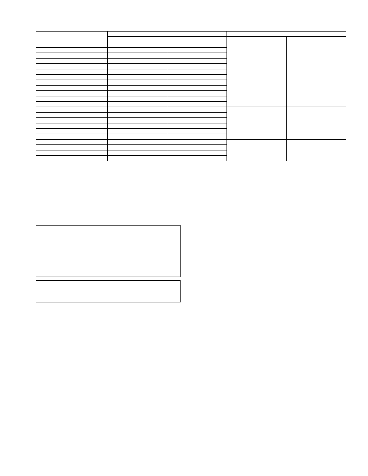
Table 40B — Air Quantity Limits (50AJ,AK,AW,AY,A2,A3,A4,A5)
UNIT
50AJ,AW,A2,A3020 6,000 10,000
50AK,AY,A4,A5020 4,000 10,000
50AJ,AW,A2,A3025 7,500 12,500
50AK,AY,A4,A5025 5,000 12,500
50AJ,AW,A2,A4027 8,100 13,500
50AK,AY,A3,A5027 5,400 13,500
50AJ,AW,A2,A4030 9,000 15,000
50AK,AY,A3,A5030 6,000 15,000
50AJ,AW,A2,A4035 10,500 17,500
50AJ,AW036 10,500 17,500
50AK,AY,A3,A5035 7,000 17,500
50AK,AY036 7,000 17,500
50AJ,AW,A2,A4040 12,000 20,000
50AJ,AW041 12,000 20,000
50AK,AY,A3,A5040 8,000 20,000
50AK,AY041 8,000 20,000
50AJ,AW,A2,A4050 13,500 20,000
50AK,AY,A3,A5050 10,000 20,000
50AJ,AW051 18,000 27,000
50AJ,AW,A2,A4060 18,000 27,000
50AK,AY051 12,000 27,000
50AK,AY,A3,A5060 12,000 27,000
*Operation at these levels may be limited by entering evaporator air wet bulb temperatures.
Min CFM Max CFM* Min CFM Max CFM
COOLING ELECTRIC HEAT
6,000 15,000
10,500 20,000
15,000 27,000
CONTROLS QUICK START
The following section will provide a quick user guide to setting up and configuring the A Series units with ComfortLink™
controls. See Basic Control Usage section on page 3 for information on operating the control. For wiring information, refer
to unit wiring diagrams in the Major System Components section on page 101.
IMPORTANT: The ComfortLink controls provide the user
with numerous configuration options such as set points,
demand levels, reset, and many others. If the building
owner or design engineer has not provided specific recommendations for these configuration settings, it is suggested
that the installer do not make changes to the default factory
settings. The factory-configured default values are appropriate for many applications.
IMPORTANT: The unit is shipped with the unit control
disabled. Enable the control by setting Local Machine Disable (Service Test
STOP) to No.
Two-Stage Constant Volume Units with
Mechanical Thermostat — To configure the unit, per-
form the following:
1. The type of control is configured under Configuration
UNITC.TYP. Set C.TYP to 4 (TSTAT 2 STG).
2. Remove jumpers from R-W2 and W2-W1 on TB4 in the
control box.
3. See Economizer Options section on page 28 for additional economizer option configurations.
4. See Exhaust Options section on page 29 for additional
exhaust option configurations.
Two-Stage Constant Volume Units with Space
Sensor —
1. The type of control is configured under Configuration
2. Under Configuration
the space sensor by setting SPT.S to ENBL (enable).
3. Install jumpers between R-W2 and W2-W1 on TB4 in
the control box.
4. The space temperature set points are configured under the
Setpoints menu. The heating and cooling set points may
To configure the unit, perform the following:
UNITC.TYP. Set C.TYP to 6 (SPT 2 STG).
UNITSENSSPT.S, enable
be configured. See the Heating Control and Cooling
Control sections on pages 50 and 37 for further description on these configurations. The following set points
may be configured:
OHSP Occupied Heat Setpoint
OCSP Occupied Cool Setpoint
UHSP Unoccupied Heat Setpoint
UCSP Unoccupied Cool Setpoint
GAP Heat-Cool Setpoint Gap
5. The degrees of demand from the space temperature set
points are configured under the Configuration
D.LV.T
submenu. See the Heating Control and Cooling Control
sections for further description on these configurations.
The following set points may be configured:
L.H.ON Demand Level Lo Heat On
H.H.ON Demand Level Hi Heat On
L.H.OF Demand Level Lo Heat Off
L.C.ON Demand Level Lo Cool On
H.C.ON Demand Level Hi Cool On
L.C.OF Demand Level Lo Cool Off
6. Under Configuration
UNITCV.FN, set CV.FN to 1
for continuous fan or 0 for automatic fan.
7. To program time schedules, set SCH.N=1 under Config-
uration
CCNSC.OVSCH.N to configure the
control to use local schedules.
8. Under the Timeclock
SCH.L submenu, enter the
desired schedule. See Time Clock Configuration section
on page 75 for further description of these configurations.
9. Under the Configuration
CCNSC.OV submenu, the
following schedules and overrides should be configured:
O.T.L. Override time limit
SPT.O SPT override enabled?
T58.O T58 override enabled?
10. See Economizer Options section on page 28 for additional economizer option configurations.
11. See Exhaust Options section on page 29 for additional
exhaust option configurations.
27

Variable Air Volume Units Using Return Air
Sensor or Space Temperature Sensor —
figure the unit, perform the following:
1. The type of control is configured under Configuration
UNITC.TYP. Set C.TYP to 1 (VAV-RAT) for return
air sensor. Set C.TYP to 2 (VAV-SPT) for space temperature sensor.
NOTE: For VAV with a space sensor (VAV-SPT), under
Configuration
space sensor by setting SPT.S to ENBL.
2. Install jumpers between R-W2 and W2-W1 on TB4 in
the control box.
3. The space temperature set points and the supply air set
points are configured under the Setpoints menu. The
heating and cooling set points must be configured. See
the Heating Control and Cooling Control sections for
further description on these configurations. Configure the
following set points:
OHSP Occupied Heat Setpoint
OCSP Occupied Cool Setpoint
UHSP Unoccupied Heat Setpoint
V. C . O N VAV Occupied Cool On Delta
V. C . O F VAV Occupied Cool Off Delta
SASP Supply Air Setpoint
4. To program time schedules, make sure SCH.N=1 under
Configuration
the control to use local schedules.
5. Under the Timeclock
sired schedule. See Time Clock Configuration section on
page 75 for further description of these configurations.
6. Under Configuration
ic Pressure Setpoint should be configured.
SP.SP Static Pressure Setpoint
7. If supply air temperature reset is desired, under the
Configuration
points should be configured:
RS.CF EDT Reset Configuration
RTIO Reset Ratio (if RS.CF = 1 or 2)
LIMT Reset Limit (if RS.CF = 1 or 2)
RES.S EDT 4-20 mA Reset Input (if RS.CF = 3)
NOTE: Configure either RTIO and LIMT or RES.S. All three
are not used.
8. See the Economizer Options section on this page for additional economizer option configurations.
9. See the Exhaust Options section on page 29 for additional
exhaust option configurations.
UNITSENSSPT.S, enable the
CCNSC.OVSCH.N to configure
SCH.L submenu, enter the de-
SP
EDT.R submenu, the following set
SP.SP, the supply duct Stat-
To con-
Multi-Stage Constant Volume Units with
Mechanical Thermostat —
form the following:
1. Under Configuration
(TSTAT MULTI).
2. Remove jumpers from R-W2 and W2-W1 on TB4 in the
control box. Connect thermostat to TB4.
3. Under the Setpoints menu, set the following
configurations:
SA.HI Supply Air Set Point Hi
SA.LO Supply Air Set Point Lo
4. See the Economizer Options section on this page for additional economizer option configurations.
To configure the unit, per-
UNITC.TYP, set C.TYP to 3
5. See the Exhaust Options section on page 29 for additional
exhaust option configurations.
Multi-Stage Constant Volume Units with
Space Sensor —
following:
1. Under Configuration
(SPT MULTI).
2. Install jumpers between R-W2 and W2-W1 on TB4 in
the control box.
3. Under the Setpoints menu, the following configurations
should be set:
OHSP Occupied Heat Setpoint
OCSP Occupied Cool Setpoint
UHSP Unoccupied Heat Setpoint
UCSP Unoccupied Cool Setpoint
GAP Heat-Cool Setpoint Gap
SA.HI Supply Air Set Point Hi
SA.LO Supply Air Set Point Lo
4. The degrees of demand from the space temperature set
points are configured under the Configuration
submenu. See the Heating Control and Cooling Control
sections for further description on these configurations.
Configure the following set points:
L.H.ON Demand Level Lo Heat On
H.H.ON Demand Level Hi Heat On
L.H.OF Demand Level Lo Heat On
L.C.ON Demand Level Lo Cool On
H.C.ON Demand Level Hi Cool On
L.C.OF Demand Level Lo Cool On
5. Under Configuration
the space sensor by setting SPT.S to ENBL.
6. Under Configuration
for continuous fan or 0 for automatic fan.
7. To program time schedules, set SCH.N=1 under Config-
uration
trol to use local schedules.
8. Under the Timeclock
sired schedule. See Time Clock Configuration section on
page 75 for further description of these configurations.
9. See the Economizer Options section below for additional
economizer option configurations.
10. See the Exhaust Options section on page 29 for additional
exhaust option configurations.
CCNSC.OVSCH.N to configure the con-
Economizer Options — Under the Configuration
ECON submenu, the following set points may be configured:
EC.EN Economizer Enabled?
EC.MN Economizer Min.Position
EC.MX Economizer Maximum Position
E.TRM Economizer Trim for SumZ?
E.SEL Econ Changeover Select
OA.E.C OA Enthalpy Change Over Select
OA.EN Outdoor Enthalpy Compare Value
OAT.L High OAT Lockout Temp
O.DEW OA Dew Point Temp Limit
ORH.S Outside Air RH Sensor
Configuration
the minimum damper position.
To configure the unit, perform the
UNITC.TYP, set C.TYP to 5
D.LV.T
UNITSENSSPT.S, enable
UNITCV.FN, set CV.FN to 1
SCH.L submenu, enter the de-
ECONEC.MN should always be set for
28

Indoor Air Quality (IAQ) Options
DEMAND CONTROLLED VENTILATION — Under
Configuration
parameters should be set to establish the minimum and maximum points for outdoor air damper position during demand
controlled ventilation (DCV):
EC.MN Economizer Min.Position
IAQ.M IAQ Demand Vent Min.Pos.
Configuration
absolute minimum vent position (or maximum reset) under
DCV.
Configuration
minimum damper position (or with no DCV reset). This is also
referenced in the economizer section.
IAQDCV.C, the following configuration
IAQDCV.CIAQ.M is used to set the
IAQDCV.CEC.MN is used to set the
Exhaust Options — The A Series units can be config-
ured with constant volume 2-stage power exhaust or modulating power exhaust. The following exhaust options should be
configured.
Configuration
Option) — For two-stage exhaust, under the Configuration
BP submenu, configure the following:
BP.P1 Power Exhaust On Setp.1
BP.P2 Power Exhaust On Setp.2
Configuration
Option) — For modulating exhaust, in the Configuration
BP submenu, configure the following:
BP.SP Building Pressure Setp.
BP
BP
BF.CF=1 (Two-Stage Exhaust
BF.CF=2 (Modulating Power Exhaust
Programming Operating Schedules — The
ComfortLink™ controls will accommodate up to eight different schedules (Periods 1 through 8), and each schedule is
assigned to the desired days of the week. Each schedule
includes an occupied on and off time. As an example, to set an
occupied schedule for 8 AM to 5 PM for Monday through
Friday, the user would set days Monday through Friday to ON
for Period 1. Then the user would configure the Period 1
Occupied From point to 08:00 and the Period 1 Occupied To
point to 17:00. To create a different weekend schedule, the user
would use Period 2 and set days Saturday and Sunday to ON
with the desired Occupied On and Off times. To create a schedule, perform the following procedure:
NOTE: By default, the time schedule periods are programmed
for 24 hours of occupied operation.
1. Scroll to the Configuration mode, and select CCN
CONFIGURATION (CCN). Scroll down to the Schedule
Number (Configuration
password protection has been enabled, the user will be
prompted to enter the password before any new data is
accepted. SCH.N has a range of 0 to 99. The default value is 1. A value of 0 is always occupied, and the unit will
control to its occupied set points. A value of 1 means the
unit will follow a local schedule, and a value of 65 to 99
means it will follow a CCN schedule. Schedules 2 to 64
are not used as the control only supports one internal/local schedule. If one of the 2 to 64 schedules is configured,
then the control will force the number back to 1. Make
sure the value is set to 1 to use a local schedule.
2. Enter the Time Clock mode. Scroll down to the LOCAL
TIME SCHEDULE (SCH.L) sub-mode, and press
ENTER. Period 1 (PER.1) will be displayed. Press ENTER to configure Period 1.
3. Configure the beginning of the occupied time period for
Period 1 (OCC). Scroll down to OCC and press ENTER
to go into Edit mode. The first two digits of the 00.00 will
start flashing. Use the UP or DOWN key to display the
CCNSC.OVSCH.N). If
correct value for hours, in 24-hour (military) time. Press
ENTER and hour value is saved and the minutes digits
will start flashing. Use the same procedure to display and
save the desired minutes value. Press ESCAPE.
4. Configure the unoccupied time for period 1 (UNC).
Scroll down to UNC and press ENTER to go into Edit
mode. The first two digits of the 00.00 will start flashing.
Use the UP or DOWN key to display the correct value for
hours, in 24-hour (military) time. Press ENTER and hour
value is saved and the minutes digits will start flashing.
Use the same procedure to display and save the desired
minutes value. Press ESCAPE.
5. Scroll to DAYS and press ENTER. Scroll down to the
MON point. This point indicates if schedule 1 applies to
Monday. Use the ENTER command to go into Edit
mode, and use the UP or DOWN key to change the display to YES or NO. Scroll down through the rest of the
days and apply schedule 1 where desired. The schedule
can also be applied to a holiday. Press ESCAPE.
6. The first schedule is now complete. If a second schedule
is needed, such as for weekends or holidays, scroll down
and repeat the entire procedure for period 2 (PER.2). If
additional schedules are needed, repeat the process for as
many as are needed. Eight schedules are provided.
SERVICE TEST
General —
ture, which is intended to allow a service person to force the
unit into different modes of operation to test them. To use this
feature, enter the Service Test category on the local display and
place the unit into the test mode by changing Service
Te st
TEST from OFF to ON. The display will prompt for the
password before allowing any change. The default password is
1111. Once the unit enters the Service Test mode, the unit will
shut down all current modes.
TEST — The TEST command turns the unit off (hard stop)
and allows the unit to be put in a manual control mode.
STOP — The STOP command completely disables the unit
(all outputs turn off immediately). Once in this mode, nothing
can override the unit to turn it on. The controller will ignore all
inputs and commands.
S.STP — Setting Soft Stop to YES turns the unit off in an
orderly way, honoring any time guards currently in effect.
FAN. F — By turning the FAN FORCE on, the supply fan is
turned on and will operate as it normally would, controlling
duct static pressure on VAV applications or just energizing the
fan on CV applications. To remove the force, press ENTER
and then press the UP and DOWN arrows simultaneously.
F. 4 . C H — The 4-Inch Filter Change Mode variable is used to
service the unit when 4-in. filters are used. When the filters
need to be changed, set Service Test
will be placed in Service Test mode and the economizer will
move to the 40% open position to facilitate removal of the 4-in.
filters. After the filters have been changed, set Service
Te st
F. 4 . C H = NO to return the unit to normal operation.
The remaining categories: INDP, FANS, COOL, and
HEAT are sub-modes with separate items and functions. See
Table 41.
The units are equipped with a Service Test fea-
F. 4 . C H = YES. The unit
Service Test Mode Logic — Operation in the Service
Test mode is sub-mode specific except for the Independent submode. Leaving the sub-mode while a test is being performed
and attempting to start a different test in the new sub-mode will
cause the previous test to terminate. When this happens, the
new request will be delayed for 5 seconds. For example, if compressors were turned on under the COOL sub-mode, any attempt to turn on heating stages within the HEAT sub-mode
would immediately turn off the compressors and, 5 seconds later, the controller would honor the requested heat stages.
29

However, it is important to note that the user can leave a
Service Test mode to view any of the local display modes and
the control will remain in the Service Test mode.
Independent Outputs — The INDP sub-mode items
can be turned on and off regardless of the other category states.
For example, the alarm relay can be forced on in the INDP
sub-mode and will remain on if compressor relays are requested in the COOL sub-mode.
Fans in Service Test Mode — Upon entering the
FA NS sub-mode, the user will be able to turn the supply fan on
and off, set the supply fan VFD speed, and turn the condenser
fans on and off.
Cooling in Service Test Mode — The COOL sub-
mode offers different cooling service tests.
The user has manual relay control of individual compressors. If the user energizes mechanical cooling, the supply fan
and the outdoor fans will be started automatically. During
mechanical cooling, the unit will protect itself. Compressor
diagnostics are active, monitoring for high discharge pressure,
low suction pressure, etc. The user can also turn the hot gas
bypass valve on and off.
NOTE: It is crucial that proper compressor rotation be verified
during the service test. Each compressor must be tested
individually. After starting each compressor, the control will
check the suction pressure after 5 seconds of run time. If the
control does not see a sufficient decrease in suction pressure
after 5 seconds, mechanical cooling will be shut down, and an
alarm will be generated (A140). This alarm requires a manual
reset. If this alarm occurs, do not attempt a restart of the
compressor and do not attempt to start any other compressors
until the wiring to the unit has been corrected.
Heating in Service Test Mode — If unit has a ther-
mostat connected (C.TYP = 3 or 4), install the RED jumper
wires between TB4, terminals R (1), W2 (3) and W1 (4). Terminal block TB4 is located in the unit control box. Remember
to disconnect these jumpers when Test Mode is completed. The
Heat Test Mode sub-mode will offer automatic fan start-up if
the unit is not a gas heat unit. On gas heat units, the IGC feedback from the gas control units will bring the fan on as
required.
Within this sub-mode, the user has control of heat relays 1
to 6. The user can also turn on the requested heat stage.
NOTE: When service test has been completed, if unit has a
thermostat connected (C.TYP = 3 or 4), remove the RED
jumper wires at TB4, terminals R (1), W2 (3) and W1 (4).
Terminal block TB4 is located in the unit control box. Store
these jumpers in the unit control box for future use.
Table 41 — Service Test
ITEM EXPANSION RANGE UNITS POINT WRITE STATUS
TEST Service Test Mode ON/OFF MAN_CTRL
STOP Local Machine Disable YES/NO UNITSTOP config
S.STP Soft Stop Request YES/NO SOFTSTOP forcible
FAN.F Supply Fan Request YES/NO SFANFORC forcible
F.4 . CH 4 in. Filter Change Mode YES/NO FILT4CHG
INDP TEST INDEPENDENT OUTPUTS
ECON Economizer Act.Cmd.Pos. ECONCTST
E.PWR Economizer Power Test ECONPTST
E.CAL Calibrate the Economizer? ECON_CAL
E.VFD Exhaust Fan VFD Speed 0-100 % EFAN_VFD
PE.A Power Exhaust Relay A PE_A_TST
PE.B Power Exhaust Relay B PE_B_TST
PE.C Power Exhaust Relay C PE_C_TST
H.I.R Heat Interlock Relay ON/OFF HIR_TST
ALRM Remote Alarm/Aux Relay ON/OFF ALRM_TST
FANS TEST FANS
S.FAN Supply Fan Relay ON/OFF SFAN_TST
S.VFD Supply Fan VFD Speed 0-100 % SGVFDTST
CD.F.A Condenser Fan Circuit A ON/OFF CNDA_TST
CD.F.B Condenser Fan Circuit B ON/OFF CNDB_TST
COOL TEST COOLING
A1 Compressor A1 Relay ON/OFF CMPA1TST
A2 Compressor A2 Relay ON/OFF CMPA2TST
MLV Min. Load Valve (HGBP) ON/OFF MLV_TST
B1 Compressor B1 Relay ON/OFF CMPB1TST
B2 Compressor B2 Relay ON/OFF CMPB2TST
HEAT TEST HEATING
HT.ST Requested Heat Stage 0-MAX HTST_TST
HT.1 Heat Relay 1 ON/OFF HS1_TST
HT.2 Heat Relay 2 ON/OFF HS2_TST
HT.3 Relay 3 W1 Gas Valve 2 ON/OFF HS3_TST
HT.4 Relay 4 W2 Gas Valve 2 ON/OFF HS4_TST
HT.5 Relay 5 W1 Gas Valve 3 ON/OFF HS5_TST
HT.6 Relay 6 W2 Gas Valve 3 ON/OFF HS6_TST
30
 Loading...