


ZONEKIT2ZCAR
WeatherMaker® Two-Zone
Visit www.carrier.com
Installation and Start-Up Instructions
NOTE: Read the entire instruction manual before starting the installation.
This symbol → indicates a change since the last issue.
TABLE OF CONTENTS |
|
|
PAGE |
Safety Considerations..................................................................... |
1 |
Installation Considerations............................................................. |
1 |
Introduction .................................................................................... |
1 |
Installation................................................................................... |
1-4 |
Sequence Of Operation............................................................... |
4-7 |
Thermostat Wiring ...................................................................... |
6-8 |
Care And Maintenance .................................................................. |
8 |
Troubleshooting ........................................................................ |
9-11 |
Wiring Diagrams..................................................................... |
12-16 |
Wiring Diagram Notes ................................................................. |
16 |
SAFETY CONSIDERATIONS
Improper installation, adjustment, alteration, service, maintenance, or use can cause fire, electrical shock, or other conditions which may cause personal injury or property damage. Consult a qualified installer, service agency, or your distributor or branch for information or assistance. The qualified installer or agency must use factory-authorized kits or accessories when modifying this product. Refer to the individual instructions packaged with the kits or accessories when installing.
Follow all safety codes and wear safety glasses. Have fire extinguisher available. Read these instructions thoroughly and follow all warnings or cautions attached to the unit. Consult local and state building codes and Sheet Metal and Air Conditioning National Association (SMACNA) for special installation requirements.
Recognize safety information. This is the safety-alert symbol . When you see this symbol on the unit or in instructions and manuals, be alert to the potential for personal injury.
Understand the signal words DANGER, WARNING, or CAUTION. These words are used with the safety-alert symbol. DANGER identifies the most serious hazards which will result in severe personal injury or death. WARNING signifies hazards which could result in personal injury or death. CAUTION is used to identify unsafe practices which would result in minor personal injury or product and property damage.
INSTALLATION CONSIDERATIONS
→1. Install in non-condensing area with ambients between 32°F and 150°F.
2.Use vibration isolators (flex connectors) on zone dampers and ductwork to minimize noise.
3.Place dampers away from areas that may be noise sensitive.
4.TXV is required in air conditioning and heat pump applications.
 ®
®
COMFORT ZONING SYSTEM
Y2 |
T'statEqupimt |
RC-RH |
|
|
|
|
|
|
|||
Y1 |
HP |
Fnc |
Jumper |
Z C1 |
|
|
|
|
|
||
R |
Fnc |
HP |
|
Emergency |
o |
G |
Y1 |
|
3 |
||
W1 |
|
n Op |
Y2 |
||||||||
W2 DTO |
|
Fnc Ht |
Heat |
e |
|
|
|||||
|
On |
1 C |
WARNING! |
|
|||||||
C |
Off |
|
w/oF |
|
Z C1 |
|
|||||
|
On |
|
w/F |
|
Off |
HOT |
parts |
|
|
||
|
|
|
|
|
|
o |
|
|
|
|
|
G Y2 Y1 R |
|
|
|
|
n Op |
under this label |
|
||||
W1 W2 C |
|
24 VAC |
e |
Rev |
|
|
|
|
|||
|
|
|
2 C |
W1 |
W2 |
|
|||||
|
Sensors |
RC B O Y2 Y1 W1 |
|
||||||||
|
W2 G RH |
|
|||||||||
HP Duct |
|
||||||||||
|
Equipment Term. |
|
|
||||||||
|
|
|
|
|
|
||||||
→Fig. 1ÐWeatherMaker Two-Zone SystemA97292
(Shown Without Cover)
5.Use separate isolated transformer to supply power to WeatherMaker Two-Zone Center. (40va minimum, class 2, transformer, field supplied)
6.Load calculations must be performed to determine equipment size. Equipment selection is matched to block load. It is imperative equipment is not over sized.
7.Ductwork must be designed based off the sum of peak plus 25 percent oversize. It is imperative ductwork is not under sized.
INTRODUCTION
The WeatherMaker Two-Zone System allows the air conditioning and heating equipment to control temperatures in 2 distinct spaces or zones within a building. Each zone has independent temperature settings controlled by a thermostat.
NOTE: Thermostats are purchased separately.
The comfort temperature settings can change automatically through the use of schedules if programmable thermostats are selected. This allows WeatherMaker Two-Zone to change the temperature settings in zones to reflect occupancy or usage. The WeatherMaker Two-Zone System uses motorized air volume control dampers (also called zone dampers) to regulate the flow of conditioned air into the zones.
INSTALLATION
Step 1ÐCheck Equipment and Jobsite
INSPECT EQUIPMENT Ð File claim with shipping company, prior to installation, if shipment is damaged or incomplete.
Manufacturer reserves the right to discontinue, or change at any time, specifications or designs without notice and without incurring obligations.
Book |
1 |
1 |
4 |
4 |
PC 101 |
Catalog No. 809-500 |
Printed in U.S.A. |
Form ZONEKIT-8SI |
Pg 1 |
6-97 |
Replaces: ZONEKIT-2SI |
Tab |
3a |
5a |
2a |
5a |
|
|
|
|
|
|
|
Step 2ÐWiring
To prevent personal injury or possible equipment damage, disconnect the power supply before routing wire.
All wiring must comply with local, state, and national codes.
NOTE: Use No. 18 AWG color-coded, insulated (35°C min) wire. If thermostats are to be located more than 100 ft from the WeatherMaker Two-Zone Center as measured along the control voltage wires, use 16 AWG colored-coded wires to avoid excessive voltage drop. All wiring is run back to the WeatherMaker Two-Zone Center.
Step 3ÐInstall WeatherMaker Two-Zone
→NOTE: WeatherMaker Two-Zone is approved for indoor use only and should never be installed with any of its components exposed to the elements. Do not mount WeatherMaker Two-Zone Center where it will be accessible to children. Do not locate the center in areas of the home that are noise sensitive since relays are energized and de-energized during operation and may be an annoyance. Install WeatherMaker Two-Zone in an area with a temperature range between 32°F and 150°F.
Install WeatherMaker Two-Zone center in a vertical position. Locate in an area that is easily accessible in case servicing should be required.
To prevent possible damage to the WeatherMaker Two-Zone Center, do not mount on plenum, ductwork, or flush against furnace.
Step 4ÐInstall Zone Dampers
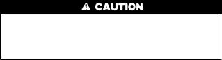
IMPORTANT: If conditions exist for possible condensing, the motor must be positioned for adequate draining. (See Fig. 2.)
NOTE: If a multi-damper enabler is used to link dampers together, then add 5va per damper to the transformer power supply rating. Reference multi-damper enabler Installation Instructions.
Zone dampers may be installed in any direction.
Install dampers so the actuator is visible for inspection and accessible in the event it would ever need service. The black mark on the end of the damper shaft represents the position of the damper blade.
DAMPER MOUNTING
BRACKET
insulate over the actuator assembly. Make sure insulation does not interfere with operation of actuator.
Before insulating the ductwork, check for proper damper operation. Apply 24vac between COM and OPN to open the damper and COM and CLS to close the damper. (See Fig. 3.) The damper will modulate counter-clockwise to open and clockwise to close.
|
AIRFLOW |
AIRFLOW |
INDICATOR |
MOUNTING |
|
|
POSITION |
HUB |
|
|
|
|
|
90 |
ANGULAR |
|
|
|
|
|
|
45 |
ROTATION |
ACTUATOR |
|
|
STOPS |
|
|
|
|
HOUSING |
|
0 |
|
|
CLS COM OPN |
|
|
QUICK BLADE |
|
|
|
RELEASE |
|
|
|
BUTTON |
|
|
MOUNTING |
(RED) |
|
|
|
|
|
|
BRACKET |
FIELD |
|
|
|
INSTALLED |
|
|
|
POWER WIRING |
|
|
|
|
|
|
A95096 |
Fig. 3ÐDamper 24-vac Connections |
|||
If in an emergency it becomes necessary to force a damper open manually, press in red quick blade release button with 1 hand and turn mounting hub to reposition the damper shaft. Release button to hold damper shaft in the new position.
To avoid noise and vibration, do not hard mount dampers to any solid structure such as joists.
ROUND METAL DUCTWORK
IMPORTANT: If application exists with all metal ductwork without insulation, flex connectors should be used on each end of the zone dampers to avoid noise and vibration.
1.Crimp end of branch duct.
2.Slip end of flex connector over zone damper and use selftapping sheet metal screw to secure. (See Fig. 4.)
ACTUATOR |
A95128
Fig. 2ÐDamper Motor Positioning
NOTE: Insulate damper using 1-1/2 in. insulation (check local codes). In areas where excessive condensing may occur, carefully
SUPPLY |
FLEX |
ZONE DAMPER |
|
CONNECTOR |
|
A95129
Fig. 4ÐRound Metal Ductwork
3.Properly seal joint using duct tape, mastic, or other approved method. Do not allow mastic to come in contact with actuator.
4.Insulate damper using 1-1/2-in. to 2-in. insulation. (Check your local codes.) (See Fig. 5.)
NOTE: All zone dampers and ductwork must be properly supported according to local codes or SMACNA standards.
RECTANGULAR METAL DUCTWORK
1. Make connections using S-lock and drives. (See Fig. 6.)
2

1/2 ² STEEL STRAP |
FLEXIBLE |
ZONE |
||||||||
|
|
|
|
|
|
|
|
|
DUCT |
DAMPER |
|
|
|
|
|
|
|
|
|
|
|
|
|
|
|
|
|
|
|
|
|
|
|
|
|
|
|
|
|
|
|
|
|
|
|
|
|
|
|
|
|
|
|
|
|
|
|
|
|
|
|
|
|
|
|
|
|
|
|
|
|
|
|
|
|
|
|
|
|
|
|
|
|
|
|
|
|
|
|
|
|
|
|
|
|
|
|
|
|
|
|
|
|
|
|
|
|
|
|
|
|
|
|
|
|
|
|
|
|
|
Fig. 5ÐInsulated Round Metal DuctworkA95130
 S-LOCK
SUPPLY
AIR DUCT
DRIVE |
ZONE |
|
DAMPER |
|
A92478 |
Fig. 6ÐRectangular Metal Ductwork |
|
2. Properly seal joint using duct tape, mastic, or other approved method. Do not allow mastic to come in contact with actuator.
3. Insulate damper using 1-1/2-in. to 2-in. insulation. (Check your local codes.) (See Fig. 7.)
1 1/2 " TO 2" INSULATION
A95131
Fig. 7ÐInsulated Rectangular Metal Ductwork
NOTE: All zone dampers and ductwork must be properly supported according to local codes or SMACNA standards.
NOTE: There should be a minimum of 4 ft between the zone damper and the first branch duct if more than 1 branch duct is downstream of the zone damper.
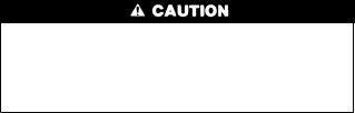
ROUND FLEXIBLE DUCTWORK
1.Slip 1 end of flexible ductwork over 1 end of zone damper. (See Fig. 8.)
2.Secure the flexible duct to zone damper using SMACNA or other approved method.
3.Properly seal joint using duct tape, mastic, or other approved method. Do not allow mastic to come in contact with actuator.
A95132
Fig 8ÐRound Flexible Ductwork
4.Insulate damper using 1-1/2-in. to 2-in. insulation. (Check your local codes.) (See Fig. 9.)
NOTE: All zone dampers and ductwork must be properly supported according to local codes or SMACNA standards.
 1/2 ² STEEL STRAP
A95133
Fig. 9ÐInsulated Round Flexible Ductwork
RECTANGULAR FIBROUS GLASS DUCTWORK
1.Insert 1 end of zone damper into 1 end of fibrous glass ductwork approximately 2 to 3 in. (See Fig. 10.)
FIBROUS
GLASS |
FIELD |
|
SUPPLIED |
||
DUCTWORK |
||
SCREWS |
||
|
||
|
ZONE |
|
|
DAMPER |
2² TO 3²
A92480
Fig. 10ÐRectangular Fibrous Glass Ductwork
2.Screw field-supplied screws and tabs into zone damper.
3.Properly seal joint using duct tape, mastic, or other approved method. Do not allow mastic to come in contact with actuators
4.Insulate damper using 1-1/2-in. to 2-in. insulation. (Check your local codes.) (See Fig. 11.)
 1 1/2 ² TO 2²
INSULATION
A95134
Fig. 11ÐInsulated Rectangular Fibrous Glass Ductwork
3
Step 5ÐInstall Barometric Bypass Damper
NOTE: The barometric bypass damper is a critical part of the WeatherMaker Two-Zone System for control of minimum airflow and noise reduction. It is recommended that the bypass be installed.
The bypass should be installed according to local codes and SMACNA standards. Be sure the bypass is properly supported.
For proper installation, refer to the Installation Instructions packaged with the barometric bypass.
Failure to properly install the bypass damper can cause permanent damage to the HVAC equipment. For single-speed furnace applications, the bypass air must never exceed 25 percent.
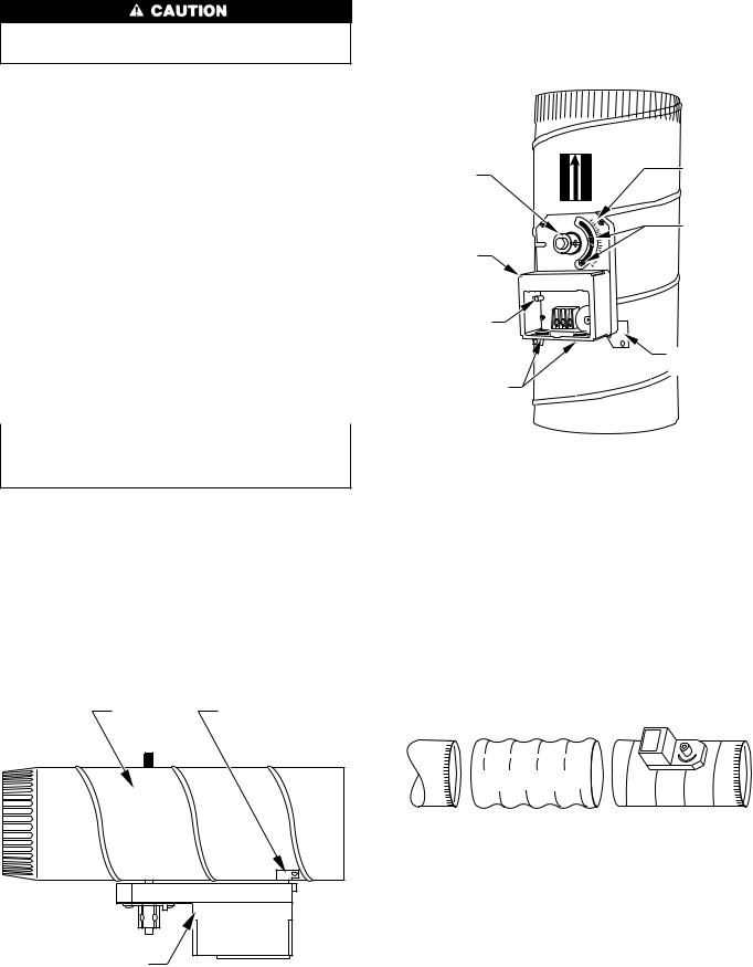
→Step 6ÐInstall Leaving Air Temperature Duct Sensor
Locate duct temperature sensor in main supply trunk after heating and cooling coil and before the bypass damper and before the first branch. The duct sensor must be radiant shielded to prevent heat from affecting the correct air temperature.
1.Drill 1/4-in. hole at location in supply trunk where sensor will be installed.
2.Insert sensor in hole and use as template to mark 2 mounting holes.
3.Drill two 1/16-in. holes to accept No. 6 screws through pre-drilled holes in duct temperature sensor back plate.
4.Use 2 No. 6 sheet metal screws to mount duct temperature sensor to unit.
5.Connect sensor to 2-conductor wire using provided wire nuts. (See Fig. 12 for connection to equipment controller.)
→Step 7ÐInstall Heat Pump (HP) Temperature Sensor
The HP temperature sensor is required in all heat pump/fan coil installations. It is not used in dual fuel (heat pump/furnace installation.) It measures the indoor coil temperature. The sensor is to be installed downstream of the indoor coil, but before the electric heaters. It can be installed through the wall of the fan coil or may be located entirely inside the fan coil near the blower inlet. Anchor firmly in place with cable ties so that it cannot interfere with the blower wheel. To activate the HP temperature sensor, remove factory supplied resistor from HP terminal block and replace with sensor leads. When activated, the HP temperature sensor has built in LAT set points of 50°F and 45°F in the cooling mode, and 105°F and 110°F in the heating mode. This is non-adjustable. (See Fig. 12 for connection to WeatherMaker Two-Zone center.)
SEQUENCE OF OPERATION
Step 1ÐSequence of Events for a Normal Heating or Cooling Cycle
The thermostats will determine if active heating or cooling is required. If so, the WeatherMaker Two-Zone System will perform the following:
· Make sure all zone dampers are fully open.
·Energize HVAC equipment fan.
·Energize heating or cooling equipment. The equipment may be a compressor, furnace, strip heater, etc.
·Set zone damper to the open or closed position based upon individual zone demand.
·Energize additional stages of heating or cooling if the thermostat demand warrants.
·Turn off heating or cooling equipment when all zones are satisfied.
·Open all zone dampers when equipment is turned off (after 90 sec delay).
This is the basic sequence of operation for the WeatherMaker Two-Zone System. The actual control of the dampers, HVAC equipment, and system fan will change with the configuration of the system. Depending upon the configuration, WeatherMaker Two-Zone can control heat pumps, furnaces, and dual fuel applications, (dual fuel will require a third party relay interface).
Step 2ÐSelection of a System Mode
The first step in any heating or cooling cycle requires WeatherMaker Two-Zone to receive an input from any thermostat located in a zone. WeatherMaker Two-Zone will then prepare to operate the heating or cooling equipment as requested by the thermostat. (See Fig. 12.)
Step 3ÐPre-Positioning Dampers and Starting System Fan
In order to minimize noise and enhance system operation, WeatherMaker Two-Zone maintains fully open zone dampers prior to starting the system fan or the heating/cooling equipment. The intent is to provide the HVAC equipment with unrestricted ductwork and to reduce pressure surges. WeatherMaker Two-Zone also fully opens the dampers whenever a heating or cooling cycle is completed (this is done after a 90 sec delay). All zone dampers will remain fully open until the next heating or cooling cycle.
The other reason for opening the dampers is to provide unrestricted ductwork to other equipment which is not directly controlled by WeatherMaker Two-Zone. One example may be a Heat Recovery Ventilator. If WeatherMaker Two-Zone is not actively controlling the HVAC system, then it must not impose any control influences (such as closed zone dampers) on the system and prevent proper operation of other devices.
Only the zone 1 thermostat controls continuous fan operation. When the zone 1 thermostat has the fan selector switch in the AUTO position, the fan will operate only when the heating and cooling equipment is operating. When the zone 1 thermostat has the fan selector switch in the ON position, the fan will operate continuously. Zone 2 will not control this.
Step 4Ð HVAC Equipment Connections
The WeatherMaker Two-Zone relay outputs are shown in Table 1. The Y1 and Y2 contacts are used for the compressor contactor only. WeatherMaker Two-Zone operates the heat pump by energizing the compressor contactor and controlling the reversing valve through the O relay output. The W1 and W2 contacts are always used for heat sources. These are heating only units such as furnaces, strip heaters, etc. The relay outputs for WeatherMaker Two-Zone are shown in Table 1.
Table 1ÐAvailable Heating and Cooling Stages Versus System Type
TYPE OF HVAC |
COOLING STAGE 1 |
COOLING STAGE 2 |
REVERSING VALVE |
HEAT STAGE 1 |
HEAT STAGE 2 |
REVERSING VALVE |
|
EQUIPMENT USED |
O |
O |
|||||
Single-Stage Heat |
Y1 |
Ð |
Energized |
Y1/W1 |
W2 |
De-energized |
|
Pump |
|||||||
|
|
|
|
|
|
||
2-Stage Heat Pump |
Y1 |
Y2 |
Energized |
Y1/W1 |
W2 |
De-energized |
|
Cooling Only, any |
Y1 |
Y2 |
Ð |
W1 |
W2 |
Ð |
|
Heater Type |
|||||||
|
|
|
|
|
|
4
In automatic changeover, the zoning system works on a first come first serve basis. If 1 zone is calling for heating and the other for cooling, the zone which sent its demand to the I/O center first will operate the equipment in that mode until that zone is satisfied.
→Step 5ÐDuct Temperature Optimizer (DTO) For Monitoring Leaving Air Temperature
As the WeatherMaker Two-Zone System operates through a heating or cooling cycle, the zone demands will change. This changes actual load that is applied to the HVAC equipment. If the zone airflow decreases, the cooling equipment will tend to lower supply-air temperatures which could tend to exceed the LAT trip limits. Conversely, the heating equipment will tend to raise the supply-air temperatures which could exceed high trip limits. In cooling, when the LAT reaches the non-adjustable low temperature trip limit (50°F) the LAT algorithm begins operating, closed dampers are initially opened 3 positions, then 1 position every 20 sec there after until full open. WeatherMaker Two-Zone will not shut down second-stage cooling (if used); however, if temperature continues to drop to 45°F, the zoning system will turn off both stages of cooling. If the temperature improves, the system will stay in the duct temperature optimizer mode until the LAT reaches 55°F or higher. At 55°F the LAT algorithm will reset and return dampers to their original position. In the heating mode, WeatherMaker Two-Zone will perform the same duct temperature optimization. The trip limits will be determined by the jumper setting. (See Fig. 12.) This will continue until the LAT problem is corrected.
This control helps WeatherMaker Two-Zone System cope with installations where the air conditioning system may suffer from poor ductwork, improperly sized heating or cooling equipment, and/or improper settings of the barometric bypass damper. This control is especially useful in retrofit applications where the size and routing of the ductwork may not be entirely known or satisfactory.
The duct temperature optimizer works by controlling how cold or hot the air inside the supply-air duct gets by monitoring the temperature of the air inside the supply-air system.
Whenever WeatherMaker Two-Zone is providing heating or cooling, the zone within the home that is asking for conditioned air will always have its damper fully open. The other zone in the system may or may not have an open damper depending upon its particular needs. If the ductwork is too small (or the air conditioner/heater is too large), then the zone requiring conditioned air may not be able to take enough air to allow your equipment to operate properly. WeatherMaker Two-Zone will detect this, and open up the closed damper allowing the equipment to continue to operate.
The duct temperature optimizer may be disabled on the control center. A 10k resistor can be installed in place of the duct sensor at the terminal block. By disabling the duct temperature optimizer, the LAT safety algorithm is removed from the system.
It is highly recommended that you use this control option. The heating LAT is adjustable for the duct sensor. In this Installation Instruction, you will find the section showing an adjustment for the heating LAT. (See Fig. 12.) It is very important that this temperature is properly set. For gas or oil furnaces, the temperature limit will be in the higher temperature range. For heat pumps the temperature setting should always be in the lower temperature range.
If you encounter a situation where 1 zone seems to have poor ductwork, then the WeatherMaker Two-Zone system is capable of reverting back to a fully open, constant-volume system. If this condition persists, it should always be looked upon as an indication of a HVAC problem, not a WeatherMaker Two-Zone problem.
Step 6ÐElectronic Thermostat Connection with WeatherMaker Two-Zone Control
Carrier electronic non-programmable and programmable thermostats can be connected to the WeatherMaker Two-Zone. See pre-sale literature for thermostat part numbers.
NOTE: The zone control board is only capable of 2-stage heat and 2-stage cool operation. Fig. 13 and 14 will reflect these applications only. Review and understand the following items before installing.
THERMOSTAT SETUP
1.Thermostat will not operate unless both R and C are connected to zone module input.
2.If selected thermostat is a heat pump (HP) or 2-speed (2S) model, convert thermostat to air conditioning operation. This will assure that Y signals are generated for cooling, and W signals are generated for heating from thermostat to zone module input. The thermostat O/W2 output will now be the second-stage heat call. If installation is a heat pump system, the zone control board will provide proper output signal to heat pump.
3.Select "Zoning" option on thermostat. This will disable the Timeguard and 4-cycle per hr (cph) protection built into thermostat. Let zone control board perform the Timeguard and cycle protection. Refer to thermostat Installation Instruction under Zoning for more detail.
4.The zone 1 thermostat is the only thermostat that can control continuous fan operation with zoning. Connect G between zone 1 thermostat and zone 1 input on zone control module.
5.Follow all safety and installation considerations outlined in the thermostat Installation Instructions.
ZONE CONTROL BOARD SETUP
1.Configure zone control board jumper for Tstat (thermostat) Fnc option only. Do not use Tstat HP option. When Tstat Fnc is selected this will setup control inputs to recognize Y1 and Y2 for firstand second-stage cooling, W1 and W2 for firstand second-stage heating.
2.Configure zone control board for either Equipmt (equipment), HP or Fnc. When a heat pump system is used, Equipmt HP mode should be selected. The zone control board will provide the proper output signal to the heat pump. When a gas/electric furnace is used, Equipmt Fnc mode should be selected for proper output signal.
3.Configure zone control board for either Fnc Ht, w/f (with fan), or w/of (without fan). With Fan mode should be selected when a heat pump is installed and fan is needed to come on immediately with demand. Without Fan mode should be selected when fan is controlled by gas/electric furnace.
4.Configure zone control board for either DTO On or Off. When DTO On is selected (Factory default) and if a LAT trip occurs, closed dampers will begin opening to try and keep equipment running by maintaining proper air temperatures. However, if LAT temperatures exceed their limits, equipment will start staging down. When DTO Off is selected, equipment will stage down. Closed dampers will not open on inial trip, however if LAT temperatures exceed their limits, control will lockout and damper will open.
5
 Loading...