


V2203-DI
Diesel Engine
62--11362 Rev --
WORKSHOP MANUAL
for
V2203-DI (26--00128)
Tier 4i
R

WORKSHOP MANUAL
DIESEL ENGINE
V2203-DI (26-00118)
Tier 4i

i
62--11362
TABLE OF CONTENTS
PARAGRAPH NUMBER Page
SAFETY PRECAUTIONS iv...................................................................
SPECIFIC WARNING AND CAUTION STATEMENTS iv..........................................
General 1--1......................................................................................
1.1 ENGINE IDENTIFICATION 1--1............................................................
Engine Serial Number 1--1.......................................................................
1.2 ENGINE SPECIFICATIONS 1--2............................................................
1.3 CYLINDER NUMBER 1--3.................................................................
1.4 GENERAL PRECAUTIONS 1--3............................................................
1.5 TORQUE SPECIFICATIONS 1--4...........................................................
1.5.1 Torque Specifications For Special Use Screws, Bolts and Nuts 1--4..........................
1.5.2 Torque Specifications For General Use Screws, Bolts and Nuts 1--4..........................
1.6 TROUBLESHOOTING 1--5................................................................
1.7 SERVICING SPECIFICATIONS 1--7........................................................
1.7.1 Engine Body 1--7......................................................................
1.7.2 Lubricating System 1--11................................................................
1.7.3 Cooling System 1--11...................................................................
1.7.4 Fuel System 1--11......................................................................
1.7.5 Electrical System 1--12..................................................................
1.8 CHECK AND MAINTENANCE 1--13..........................................................
1.8.1 Checking Engine Oil Level 1--13..........................................................
1.8.2 Checking Coolant Level 1--13............................................................
1.8.3 Checking Fuel Hose 1--13...............................................................
1.8.4 Bleeding Fuel System 1--14..............................................................
1.8.5 Checking V--Belt 1--14..................................................................
1.8.6 Changing Engine Oil 1--14...............................................................
1.8.7 Valve Clearance 1--15..................................................................
1.8.8 Fuel Injection 1--15.....................................................................
1.9 SPECIAL TOOLS 1--16.....................................................................
1.9.1 Diesel Engine Compression Tester (Glow Plug) 1--16.......................................
1.9.2 Adapter, Injector T o Tester Hose 1--16....................................................
1.9.3 Tester Injector Nozzle 1--16..............................................................
1.9.4 Replacement Bowl, Tester Injector Nozzle 1--16............................................
1.9.5 Adapter, Injector Line 1--16..............................................................
1.9.6 Oil Pressure Tester 1--17................................................................
1.9.7 Auxiliary Socket For Fixing Crankshaft Sleeve 1--17........................................
1.9.8 Gauge, Belt Tension 1--17...............................................................
1.9.9 Tester, Belt Tension 1--17................................................................
1.9.10 Rubber Band 1--17.....................................................................
1.9.11 Main Bearing Install Tool 1--17...........................................................
1.9.12 Main Bearing Extract Tool 1--17..........................................................
1.9.13 Valve Guide Replacing Tool 1--18.........................................................
1.9.14 Bushing Replacing T ools 1--18...........................................................
1.9.15 Flywheel Stopper 1--18..................................................................
1.9.16 Crankshaft Bearing 1 Replacing Tool 1--19.................................................

ii
62-11362
PARAGRAPH NUMBER
Page
ENGINE BODY 2--1...............................................................................
2.1 CHECKING AND ADJUSTING 2--1.........................................................
2.1.1 Compression Pressure 2--1.............................................................
2.1.2 Top Clearance 2-- 1....................................................................
2.2 DISASSEMBLY AND REASSEMBLY 2--2....................................................
2.2.1 Draining Coolant And Engine Oil 2--2....................................................
2.2.2 External Components 2--2..............................................................
2.2.3 Cylinder Head And V alves 2--3..........................................................
2.2.4 Injection Pump and Gear Case 2--6......................................................
2.2.5 Oil Pan and Oil Strainer 2--12............................................................
2.2.6 Piston and Connecting Rod 2--13.........................................................
2.2.7 Crankshaft 2--15.......................................................................
2.3 SERVICING 2--18.........................................................................
2.3.1 Cylinder Head And V alves 2--18..........................................................
2.3.2 Timing Gears, Camshaft and Fuel Camshaft 2--23..........................................
2.3.3 Piston and Connecting Rod 2--26.........................................................
2.3.4 Crankshaft 2--28.......................................................................
2.3.5 Cylinder 2--33..........................................................................
LUBRICATING SYSTEM 3--1.......................................................................
3.1 CHECKING AND ADJUSTING 3--1.........................................................
3.1.1 Engine Oil Pressure 3--1...............................................................
3.2 SERVICING 3--2.........................................................................
3.2.1 Rotor Lobe Clearance 3--2.............................................................
3.2.2 Rotor to Cover Clearance 3--2..........................................................
COOLING SYSTEM 4--1...........................................................................
4.1 CHECKING AND ADJUSTING 4--1.........................................................
4.1.1 Notched V--Belt Service 4--1............................................................
4.1.1a Poly V--Belt Service 4--1...............................................................
4.1.2 Fan Belt Damage and Wear 4--1........................................................
4.1.3 Checking Coolant Level 4--1............................................................
4.1.4 Radiator Cap 4--2.....................................................................
4.1.5 Radiator 4--2.........................................................................
4.1.6 Thermostat Opening Temperature 4--2...................................................
4.2 SERVICING 4--3.........................................................................
4.2.1 Thermostat Assembly 4--3..............................................................
4.2.2 Water Pump Assembly 4--3.............................................................

iii
62--11362
PARAGRAPH NUMBER
Page
FUEL SYSTEM 5--1...............................................................................
5.1 CHECKING AND ADJUSTING 5--1.........................................................
5.1.1 Injection Timing 5--1...................................................................
5.1.2 Shim Identification 5--1.................................................................
5.1.3 Pump Pressure Test 5--2...............................................................
5.1.4 Delivery Valve Fuel Seal 5--2...........................................................
5.2 INJECTION NOZZLE 5--3.................................................................
5.2.1 Nozzle Injection Pressure 5--3..........................................................
5.2.2 Nozzle Spraying Condition 5--3..........................................................
5.2.3 Valve Seat Tightness 5--3..............................................................
ELECTRICAL SYSTEM 6--1........................................................................
6.1 STARTER TEST 6--1......................................................................
6.1.1 Motor Test 6--1........................................................................
6.1.2 Magnetic Switch Test 6--1..............................................................
6.2 FUEL SPEED SOLENOID 6-- 2.............................................................
6.2.1 Solenoid Test 6-- 2.....................................................................
6.3 INTAKE AIR HEATER 6--3.................................................................
6.3.1 Intake Air Heater Test 6--3..............................................................

iv
62-11362
SAFETY
SAFETY PRECAUTIONS
Your Carrier Transicoldunit has been designed with the
safety of the operator inmind. During normal operation,
allmovingparts are fully enclosed to help prevent injury.
During all pre-trip inspections, daily inspections, and
problem troubleshooting, you may be exposed to
movingparts.Pleasestayclearofallmovingpartswhen
the unit is in operation and when the unit main power
switch is in the START/RUN position.
Engine Coolant
The engine is equipped with a pressurized cooling
system. Under normal operating conditions, the coolant
in the engine and radiator is under high pressure and is
very hot. Contact with hot coolant can cause severe
burns. Do not remove the cap from a hot radiator. If the
cap must be removed, do so very slowly in order to
release the pressure without spray.
Battery
This unit is equipped with a lead-acid type battery. The
battery normally vents small amounts of flammable
hydrogengas.Donotsmokewhencheckingthebattery.
A battery explosion can cause serious physical harm
and/or blindness.
SPECIFIC WARNING AND CAUTION
STATEMENTS
Tohelpidentifythe labelhazards on the unit andexplain
thelevelof awareness each onecarries, an explanation
is given with the appropriate consequences:
DANGER
DANGER -- warns against an immediate hazard which WILL result in severe personal injury ordeath.
WARNING
WARNING -- warns against hazards or unsafe conditions which COULD res ult in severe personal in-
jury or death.
CAUTION
CAUTION -- warns against potential hazard or unsafe practice which could result in minor personal
injury, or product or property damage.
NOTE
NOTE -- gives helpful information that may help and avoid equipment and property damage.
v
62-11362
The statements listed below are specifically applicable to this unit and appear elsewhere in this manual. These
recommended precautions must be understood and applied during operation and maintenance of the equipment
covered herein.
WARNING
Beware of moving V--belt and belt driven components
WARNING
When removing the radiator cap, wait at least ten minutes after the engine has stopped and cooled
down. Otherwise, hot water may discharge from the radiator, scalding anyone nearby.
WARNING
Checktheinjectionnozzleonly afterconfirming that nobody is near the spray. If the spray fromthe
nozzle contacts the human body, cells may be destroyed and blood poisoning may result.
WARNING
Secure the starter to prevent it from moving when power is applied to it.
CAUTION
Do not removethe radiator cap until the coolant temperatureis below its boiling point. Loosen the
cap slightly to relieve excess pressure before removing the cap completely.
CAUTION
Stop the engine when attempting to check and change the fuel line.
CAUTION
Stop the engine when preparing to change the engine oil.
CAUTION
Never remove the radiator cap until coolant temperature is below its boiling point. Loosen the cap
slightly to the first stop to relieve any excess pressure before removing the cap completely.
1--1 62--11362
SECTION 1
General
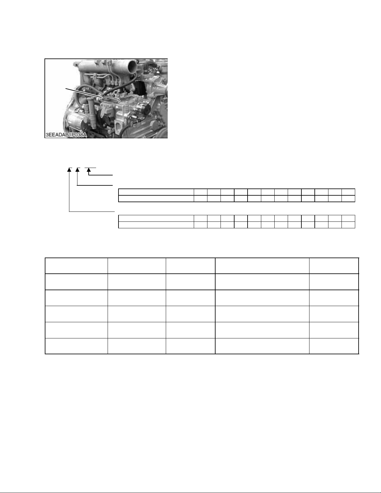
1.1 ENGINE IDENTIFICATION
S/N
When contacting Carrier Transicold, always specify
your engine model number and serial number.
The engine model and its serial number need to be
identified before the engine can be serviced or parts
replaced.
Engine Serial Number
Theengineserialnumber is an identified number forthe
engine. It is marked after the engine model number.
It indicates month and year of manufacture as follows:
S
er
i
a
l
N
um
b
er
Y A 4321
Lower 4 digits in numerals
7th Digit Alpabetical Letter (Month of Manufacture)
Alphabetical letter
A,B C,DE,FG,HJ,KL,M N,P Q,R S,T U,V W,X Y,Z
Month
6th Digit Alpabetical Letter or Numerals (Year of Manufacture).
Alphabetical letter or numerals W XY
Year 98 99 00 01 02 03 04 05 06 07 08 09
Jan Feb Mar May Jun Jul Aug Sep OctApr Nov Dec
1234 56789
V2203--
Table 1-1. Model Chart
MODEL NUMBER ENGINE TYPE
SERVICE ENGINE
PARTNUMBER
PRIMARY USE REPLACES
V2203L--DI--E3B--CTD--2
CT4--134--DI
(1700 RPM)
26--00128--00
Ultra XT, Ultra XTC, X2 1800 (2.2),
X2 2100, X2 2100A, X2 2100R
New
V2203L--DI--E3B--CTD--3
CT4--134--DI
(1800 RPM)
26--00128--01 RG Genset New
V2203L--DI--E3B--CTD--1
CT4--134--DI
(2200 RPM)
26--00128--02
UltimaXTC,ExtraXT(2.2),
X2 2500 A, X2 2500 R
New
V2203L--DI--E3B--CTD--6
CT4--134--DI
(1800 RPM)
26--00128--04 UG Genset New
V2203L--DI--E3B--CTD--4
CT4--134--DI
(1700 RPM)
26--00128--05 TM Ultra XL New
1--2
62--11632
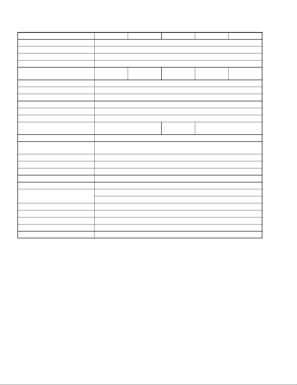
1.2 ENGINE SPECIFICATIONS
Table 1-2. Specification Chart
MODEL NUMBER 26--00128--00 26--00128--01 26--00128--02 26--00128--04 26--00128--05
TYPE Vertical, Water--cooled, 4 cycledieselengine
NUMBER OF CYLINDERS 4
BOREXSTROKE mmXmm(in.Xin.) 83 X 102.4 (3.27 X 4.03)
TOTAL DISPLACEMENT cm
3
(cu.in.) 2216 (135.2)
BRAKE HORSEPOWER
SAE Intermittent HP kW (HP) / RPM
23.65 (31.7) /
1700
23.87 (32.0) /
1800
26.85 (36.0) /
2200
23.87 (32.0) /
1800
23.65 (31.7) /
1700
MAXIMUM SPEED RPM Below 2470
IDLING SPEED RPM 900
COMBUSTION CHAMBER DirectInjection
INJECTION PUMP Bosch “K” Type Mini Pump
GOVERNOR Mechanical Governor + Electronic Governor
INJECTION NOZZLE Bosch “P” Type Hole Nozzle
INJECTION TIMING (UNPRESSURIZED) 2.5° BeforeT.D.C.
4.0° Before
T.D.C.
2.5° BeforeT.D.C.
FIRING ORDER 1-- 3--4--2
INJECTION PRESSURE
(Valve Opening Pressure)
19.35 MPa (197.5 kgf/cm
2
, 2809 psi.)
COMPRESSION RATIO 21.5 : 1
LUBRICATION SYSTEM Forced Lubrication by Pump
OIL PRESSURE INDICATION Electrical Type Switch
LUBRICATION FILTER Full Flow Synthetic Media Filter (Cartridge Type)
COOLING SYSTEM Pressurized Radiator, Forced Circulation With Water Pump
STARTING SYSTEM
Electric Starting With Starting Motor
12V,2.5 kW
STARTING SUPPORT DEVICE Intake Air Heater in Intake Manifold
FUEL Diesel Fuel No.2--D (ASTM D975)
LUBRICATING OIL *Quality Better Than CF Class (API), SAE 10W--30 or 15W--40
LUBRICATING OIL CAPACITY 14.2 L (15.0 U.S. Quarts)
Weight (DRY) kg (lbs.) 199 (439)
*See paragraph 1.8.6
1--3 62--11362
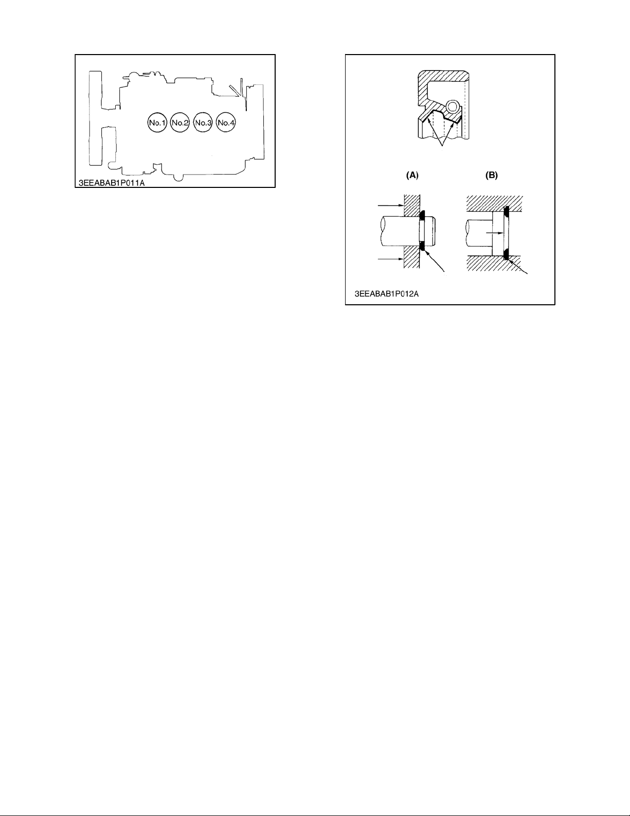
1.3 CYLINDER NUMBER
The cylinder numbers of V2203--DI series engine are
designated as shown above. The sequence of cylinder
numbers is given as No.1, No. 2, No. 3, and No. 4
starting from the gear case end of the engine.
1.4 GENERAL PRECAUTIONS
1
2
3
2
3
1. Grease
2. Force
3. Place the Sharp Edge
against the Direction of Force
A External Snap Ring
B Internal Snap Ring
During disassembly, carefully arrange removed parts in
a clean area to prevent confusion later. Screws, bolts
and nuts should be replaced in their original position to
prevent reassembly errors.
When special tools are required, use KUBOTAgenuine
special tools. Special tools which are not frequently
used should be made according to the drawings
provided.
Before disassembling orservicing live wires, makesure
to always disconnect the grounding cable from the
battery first.
Remove oil and dirt from parts before taking any
measurements.
Use only Carrier Transicold genuine parts for parts
replacements to maintain engine performance and to
ensure safety.
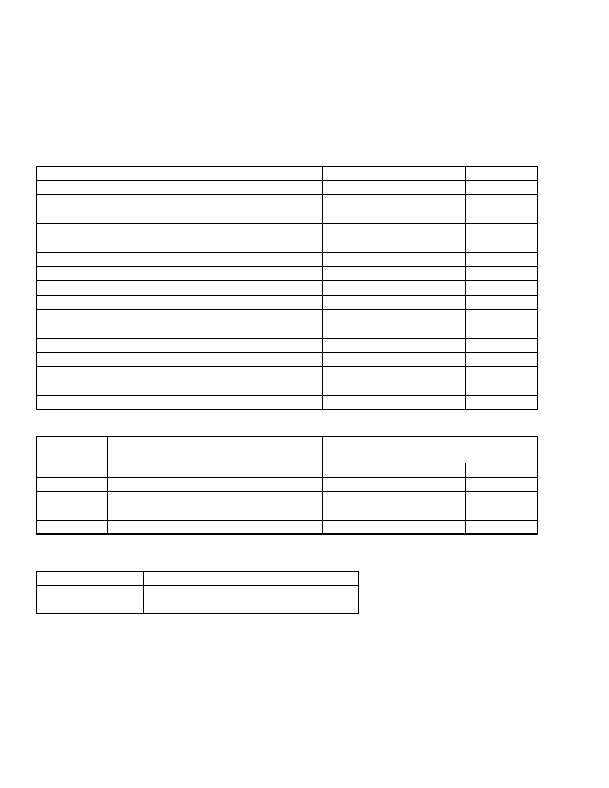
Gaskets and O--rings must be replaced during
reassembly. Apply grease to new O--rings or oil seals
before assembling.
When reassembling external or internal snap rings,
position them so that the sharp edge faces against the
direction from which force is applied.
A newly serviced or reassembled engine should be
run--in with no load for 15 minutes. Serious damage to
the engine may result otherwise.
1--4
62--11632
1.5 TORQUE SPECIFICATIONS
Screws, bolts and nuts must be tightened to the specified torque using a torque wrench. Several screws, bolts and
nuts such as those used on the cylinder head must be tightened in the proper sequence and at the proper torque.
1.5.1 Torque Specifications For Special Use Screws, Bolts and Nuts
In removing andapplyingthe screws, bolts andnuts marked with“*”, a pneumatic wrench or similartool, if employed,
must be used with care. Failure to do so may result in stripped or seized screws, bolts and nuts.
When replacing “*” marked screws, bolt and nuts, apply engine oil to their threads and seats before reassembly.
The letter “M” in size and pitch means that the screw, bolt or nut dimension is metric. The size isthe nominal outside
diameter in mm of the threads. The pitch is the nominal distance in mm between two threads.
Item
SizexPitch N.m kgf.m ft--lbs
Cylinder Head Cover Bolt M6 x 1.0 6.87 to 11.2 0.7to1.15 5.07 to 8.31
*Cylinder Head Bolt M11 x 1.25 93.2 to 98.0 9.5 to 10.0 68.8 to 72.3
*Main Bearing Case Bolt 1 M9 x 1.25 46 to 50 4.7to5.2 34.0to37
*Main Bearing Case Bolt 2 M10 x 1.25 69 to 73 7.0to7.5 51 to 54
*Flywheel Bolt M12 x 1.25 98.1 to 107 10.0 to 11.0 72.4 to 79.5
*Connecting Rod Bolt M8 x 1.0 45 to 49 4.5to5.0 33 to 36
*Rocker Arm Bracket Bolt M8 x 1.25 24 to 27 2.4to2.8 18 to 20
*Idle Gear Shaft Bolt M8 x 1.25 24 to 27 2.4to2.8 18 to 20
Crank Pulley Mounting Nut M30 x 1.5 138 to 156 14.0 to 16.0 102 to 115
*Bearing Case Cover Bolt M8 x 1.25 24 to 27 2.4to2.8 18 to 20
Nozzle Holder Clamp Bolt M10 x 1.25 26 to 29 2.6to3.0 19 to 21
Injection Pipe Retaining Nut M12 x 1.5 15 to 24 1.5to2.5 11 to 18
Overflow Pipe Assembly Retaining Bolt M6 x 1.0 9.81 to 11.2 1.0to1.15 7.24 to 8.31
Camshaft Retaining Bolt M8 x 1.25 24 to 27 2.4to2.8 18 to 20
Hi--idling Body M14 x 1.0 45 to 49 4.5to5.0 33 to 36
Starter’s Terminal B Mounting Nut M8 9.8to11 1.0to1.2 7.3to8.6
1.5.2 Torque Specifications For General Use Screws, Bolts and Nuts
Standard Screw and Bolt
Grade 4
Special Screw and Bolt
Grade 7
N.m kgf.m ft--lbs N.m kgf.m ft--lbs
M6 7.9to9.3 0.80 to 0.95 5.8to6.8 9.81 to 11.2 1.00 to 1.15 7.24 to 8.31
M8 18 to 20 1.8to2.1 13 to 15 24 to 27 2.4to2.8 18 to 20
M10 40 to 45 4.0to4.6 29 to 33 49 to 55 5.0to5.7 37 to 41
M12 63 to 72 6.4to7.4 47 to 53 78 to 90 7.9to9.2 58 to 66
Screw and bolt material grades are shown by numbers punched on the screw and bolt heads. Prior to tightening, be
sure to check out the numbers as shown below
Punched Number
Screw And Bolt Material Grade
None or 4 Standard Screw And Bolt SS41, S20C
7 Special Screw And Bolt S43C, S48C (Refined)

1--5 62--11362
1.6 TROUBLESHOOTING
Symptom
Probable Cause Solution Reference
Engine Does Not
Start
(Starter Does Not
Run)
No fuel
Air in the fuel system
Water in the fuel system
Fuel pipe clogged
Fuel filter clogged
Excessively high viscosity fo fuel or engine oil
at low temperature
Fuel with low cetane number
Incorrect injection timing
Injection nozzle clogged
Injection pump malfunctioning
Seizure of crankshaft, camshaft, piston,
cylinder or bearing
Compression leak from cylinder
Improper valve timing
Piston ring and cylinder worn
Excessive valve clearance
Battery discharged
Starter malfunctioning
Key switch malfunctioning
Wiring disconnected
Replenish fuel
Vent Air
Change fuel and
repair or replace fuel
system
Clean
Clean or change
Use specified fuel or
engine oil
Use specified fuel
Adjust
Replace
Replace
Repair or Replace
Replace head
gasket, tighten
cylinder head screw,
glow plug and nozzle
holder
Correct or replace
timing gear
Replace
Adjust
Charge
Repair or replace
Repair or replace
Connect
--
1.8.4
1.8.4
1.8.4
--
--
--
5.1.1
1.8.8
--
--
--
--
--
--
2.2.4.f
2.3.3.d
1.8.7
6.1
--
--
Engine Revolution
Is Not Smooth
Fuel filter clogged or dirty
Air cleaner clogged or dirty
Fuel leak due to loose injection pipe retaining
nut
Injection pump malfunctioning
Incorrect nozzle injection pressure
Injection nozzle stuck or clogged
Clean or change
Clean or change
Tighten retaining nut
Replace
Replace
Replace
1.8.4
--
--
5.1
5.2.1
5.2.3
Either White or Blue
Exhaust Gas Is
Observed
Excessive engine oil
Piston ring and liner worn or ring stuck
Incorrect Injection timing
Deficient compression
Reduce to specified
level
Repair or replace
Adjust
Check the cylinder
compression
pressure and top
clearance
1.8.1
2.3.3.d
5.1.1
2.1.1
Either Black or Dark
Exhaust Gas Is
Observed
Overload
Low grade fuel used
Fuel filter clogged
Air cleaner clogged
Deficient nozzle injection
Lesson load
Use specified fuel
Clean or change
Clean or change
Replace nozzle
--
--
--
--
1.8.8
Deficient Output Incorrect injection timing
Engine’s moving parts seem to be seizing
Injection pump malfunctioning
Deficient nozzle injection
Compression leak
Gas leak from exhaust system
Air cleaner dirty or clogged
Adjust
Repair or replace
Replace
Replace nozzle
Check the
compression
pressure and repair
Repair or replace
Clean or replace
5.1.1
--
5.1
5.2.2
2.1.1
--
--

1--6
62--11632
1.6 TROUBLESHOOTING (Continued)
Symptom
Probable Cause Solution Reference
Excessive Lubricant
Oil Consumption
Piston ring’s gap facing the same direction
Oilringwornorstuck
Piston ring groove worn
Valve stem and valve guide worn
Crankshaft bearing, and crank pin bearing
worn
Oil leaking due to defective seals or packing
Shift ring gap
direction
Replace
Replace worn piston
Replace
Replace
Replace
2.2.6.a
2.3.3.d
2.3.3.e
2.3.1.d
2.3.4
--
Fuel Mixed into
Lubricant Oil
Injection pump’s plunger worn
Deficient nozzle injection
Injection pump broken
Replace Injection
pump
Replace nozzle
Replace
5.1
5.2.3
5.1
Water Mixed into
Lubricant Oil
Head gasket defective
Cylinder block or cylinder head flawed
Replace
Replace
2.2.3.e
--
Low Oil Pressure Engine oil level low
Oil strainer clogged
Relief valve stuck with dirt
Relief valve spring weak or broken
Excessive oil clearance of crankshaft bearing
Excessive oil clearance of crankpin bearing
Excessive oil clearance of rocker arm
Oil passage clogged
Incorrect oil type
Oil pump defective
Replenish
Clean
Clean
Replace
Replace
Replace
Replace
Clean
Use specified type of
oil
Repair or replace
--
--
3.1.1
3.1.1
2.3.4.d
2.3.4.c
2.3.1.k
--
--
3.2
High Oil Pressure Incorrect oil type
Relief valve defective
Use specified type of
oil
Replace
--
3.1.1
Engine Overheated Engine oil level low
Fan belt broken or elongated
Coolant insufficient
Radiator net and radiator fin clogged with dust
Inside of radiator corroded
Coolant flow route corroded
Radiator cap defective
Overload running
Head gasket defective
Incorrect injection timing
Unsuitable fuel used
Replenish
Replace or adjust
Replenish
Clean
Clean or replace
Clean or replace
Replace
Loosen load
Replace
Adjust
Use specified fuel
--
--
--
--
--
--
--
--
2.2.3.e
--
--
Low Battery Charge Battery electrolyte level low
Fan belt slips
Wiring disconnected
Rectifier defective
Alternator defective
Battery defective
Replenish distilled
water and charge
Adjust belt tension or
change belt
Connect
Replace
Replace
Change
--
--
--
--
--
--
1--7 62--11362
1.7 SERVICING SPECIFICATIONS
1.7.1 Engine Body
Item
Factory Specification Allowable Limit
Cylinder Head Surface Flatness -- 0.05 mm/500mm
0.0020 in./
19.69 in.
Compression Pressure
Difference Among Cylinders
2.95 to 3.23 MPa/
290 rpm
30 to 33 kgf/cm
2
290 rpm
427 to 469 psi/
290 rpm
--
2.35 MPa/
290 rpm
24kgf/cm
2
290 rpm
341 psi/
290 rpm
10% or less
Top Clearance 0.60 to 0.70 mm
0.0236 to 0.0276 in.
--
Valve Clearance (When Cold) 0.18 to 0.22 mm
0.0071 to 0.0086 in.
--
Valve Seat Width (Intake)
Width (Exhaust)
2.12 mm
0.0835 in.
2.12 mm
0.0835 in.
--
--
Valve Seat Angle
(Intake / Exhaust)
0.79 rad.
45°
--
Valve Face Angle
(Intake / Exhaust)
0.79 rad.
45°
--
ValveStemtoValveGuide
Valve Stem
Valve Guide
Clearance
O.D.
I.D.
0.040 to 0.070 mm
0.0016 to 0.0027 in.
7.960 to 7.975 mm
0.3134 to 0.3139 in.
8.015 to 8.030 mm
0.3156 to 0.3161 in.
0.1 mm
0.0039 in.
--
--
Valve Recessing Protrusion
Recessing
0.65 mm
0.026 in.
to
0.85 mm
0.033 in.
--
--
Valve Timing (Intake Valve) Open
Close
0.1 rad. (8°)
before T.D.C.
0.35 rad. (20°)
before T.D.C
--
--
Valve Timing (Exhaust Valve) Open
Close
0.87 rad. (50°)
before B.D.C.
0.21 rad. (12°)
before B.D.C
--
--

1--8
62--11632
1.7.1 Engine Body (Continued)
Item
Factory Specification Allowable Limit
Valve Spring Free Length
Setting Load/
Setting Length
Tilt
41.7 to 42.2 mm
1.65 to 1.66 in.
118N/35.0mm
12.0 kgf / 35.0 mm
26.5 lbs. / 1.38 in.
--
41.2 mm
1.62 in.
100.0N / 35.0 mm
10.2kgf / 35.0 mm
22.5lbs /1.38 in
1.0 mm
0.039 in.
Rocker Arm Shaft to Rocker Arm
Rocker Shaft
Rocker Arm
Clearance
O.D.
I.D.
0.016 to 0.045 mm
0.00063 to 0.0017 in.
13.973 to 13.984 mm
0.55012 to 0.55055 in.
14.000 to 14.018 mm
0.55119 to 0.55188 in.
1.0 mm
0.039 in.
--
--
Push Rod Alignment -- 0.25mm
0.0098 in.
Tappet to Tappet Guide Clearance
O.D.
I.D.
0.020 to 0.062 mm
0.00079 to 0.0024 in.
23.959 to 23.980 mm
0.94327 to 0.94409 in.
24.000 to 24.021 mm
0.94489 to 0.94570 in.
0.07 mm
0.003 in.
--
_
Timing Gear
Crank Gear to Idle Gear
Idle Gear to Cam Gear
Idle Gear to Injection Pump Gear
Crank Gear to Oil Pump Gear
Backlash
Backlash
Backlash
Backlash
0.0415 to 0.1122 mm
0.001634 to 0.004417 in.
0.0415 to 0.1154 mm
0.00163 to 0.004543 in.
0.0415 to 0.1154 mm
0.001634 to 0.004543 in.
0.0415 to 0.1090 mm
0.001634 to 0.004291 in.
0.15 mm
0.0059 in.
0.15 mm
0.0059 in.
0.15 mm
0.0059 in.
0.15 mm
0.0059 in.
Idle Gear Side Clearance 0.12 to 0.48 mm
0.0048 to 0.018 in.
0.9 mm
0.04 in.
Idle Gear Shaft to Idle Gear Bushing
Idle Gear Shaft
Idle Gear Bushing
Clearance
O.D.
I.D.
0.025 to 0.066 mm
0.00099 to 0.0025 in.
37.959 to 37.975 mm
1.4945 to 1.4950 in.
38.000 to 38.025 mm
1.4961 to 1.4970 in.
0.1 mm
0.0039 in.
--
--
1--9 62--11362
1.7.1 Engine Body (Continued)
Item
Factory Specification Allowable Limit
Camshaft Side Clearance 0.07 to 0.22 mm
0.0028 to 0.0086 in.
0.3 mm
0.012 In.
Camshaft Alignment -- 0.01 mm
0.0004 in.
Cam (Lobe) Height (Intake)
Height (Exhaust)
33.27 mm
1.310 in.
33.47 mm
1.318 in.
33.22 mm
1.308 in.
33.42
1.316 in.
Camshaft Journal to Cylinder Block Bore
Camshaft Journal
Cylinder Block Bore
Clearance
O.D.
I.D.
0.050 to 0.091 mm
0.0020 to 0.0035 in.
39.934 to 39.950 mm
1.5722 to 1.5728 in.
40.000 to 40.025 mm
1.5748 to 1.5757
0.15 mm
0.00059 in.
--
--
Piston Pin Bore I.D. 25.000 to 25.013 mm
0.98425 to 0.98476 in.
25.05 mm
0.9862 in.
Second Ring to Ring Groove Clearance 0.093 to 0.128 mm
0.00367 to 0.00503 in.
0.2 mm
0.0079 in.
Oil Ring to Ring Groove Clearance 0.020 to 0.060 mm
0.00079 to 0.0023 in.
0.15 mm
0.0059 in.
Top Ring Ring Gap 0.20 to 0.35 mm
0.0079 to 0.013 in.
1.25 mm
0.0492 in.
Second Ring Ring Gap 0.40 to 0.55 mm
0.016 to 0.021 in.
1.25 mm
0.0492 in.
Oil Rng Ring Gap 0.25 to 0.45 mm
0.0099 to 0.017 in.
1.25 mm
0.0492 in.
Connecting Rod Alignment -- 0.05 mm
0.002 in.
Piston Pin to Small End Bushing
Piston Pin
Small End Bushing
Clearance
O.D.
I.D.
0.014 to 0.036 mm
0.00056 to 0.0014 in.
25.004 to 25.011 mm
0.98441 to 0.98468 in.
25.025 to 25.040 mm
0.98524 to 0.98582 in.
0.15 mm
0.0059 in.
--
--
Crankshaft Alignment -- 0.02 mm
0.0008 in.
Crankshaft Journal to Crankshaft Bearing1
Crankshaft Journal
Crankshaft Bearing1
Oil Clearance
O.D.
I.D.
0.040 to 0.118 mm
0.00158 to 0.00464 in.
59.921 to 59.940 mm
2.3591 to 2.3598 in.
59.980 to 60.039 mm
2.3615 to 2.3637 in.
0.2 mm
0.0079 in.
--
--

1--10
62--11632
1.7.1 Engine Body (Continued)
Item
Factory Specification Allowable Limit
Crankshaft Journal to Crankshaft Bearing2
Crankshaft Journal
Crankshaft Bearing2
Oil Clearance
O.D.
I.D.
0.040 to 0.104 mm
0.00158 to 0.00409 in.
59.921 to 59.940 mm
2.3591 to 2.3598 in.
59.980 to 60.025 mm
2.3615 to 2.3631 in.
0.2 mm
0.0079 in.
--
--
Crankpin to Crankpin Bearing
Crankpin
Crankpin Bearing
Oil Clearance
O.D.
I.D.
0.025 to 0.087 mm
0.00099 to 0.0034 in.
46.959 to 46.975 mm
1.8488 to 1.8494 in.
47.000 to 47.046 mm
1.8504 to 1.8522 in.
0.2 mm
0.0079 in.
--
--
Crankshaft Side Clearance 0.15 to 0.31 mm
0.0059 to 0.012 in.
0.5 mm
0.02 in.
Crankshaft Sleeve Wear -- 0.1mm
0.0059 in.
Cylinder Bore
(Standard)
(Oversize)
I.D.
I.D.
83.00 to 83.022mm
3.2678 to 3.2685 in.
83.250 to 83.272 mm
3.2776 to 3.2784 in.
83.170 mm
3.2744 in.
83.420 mm
3.2843 in.
1--11 62--11362
1.7.2 Lubricating System
Item
Factory Specification Allowable Limit
Engine Oil Pressure At Idle Speed
At Rated Speed
More Than 98 kPa
1.0 kgf/cm
2
14 psi
300 to 440 kPa
3.0 to 4.5kgf/cm
2
43 to 64 psi
50 kPa
0.5 kgf/cm
2
7psi
250 kPa
2.5 kgf/cm
2
36 psi
Engine Oil Pressure Switch Working
Pressure
50 kPa
0.5kgf/cm
2
7psi
--
Inner Rotor to Outer Rotor Clearance 0.03 to 0.14 mm
0.0012 to 0.0055 in.
0.2 mm
0.008 in.
Outer Rotor to Pump Body Clearance 0.11 to 0.19 mm
0.0044 to 0.0074 in.
0.25 mm
0.0098 in.
Inner Rotor to Cover Clearance 0.105 to 0.150 mm
0.00414 to 0.00590 in.
0.2 mm
0.008 in.
1.7.3 Cooling System
Item
Factory Specification Allowable Limit
V--Belt Tension 7.0to9.0mm(0.28to
0.35 in.) deflection at
98N(10kgf, 22 lbs.)
of force
--
Thermostat Valve Opening
Temperature
(At Beginning)
Valve Opening
Temperature
(Opened
Completely)
80.5 to 83.5°C
176.9 to 182.3°F
95°C
203°F
--
--
1.7.4 Fuel System
Item
Factory Specification Allowable Limit
Injection Pump Injection Timing 0.0568 to 0.0829 rad.
(3.25to4.75°) before
T.D.C.
--
Pump Element Fuel Tightness -- 18.63 Mpa
190.0 kgf/cm
2
2702 psi
Delivery Valve Fuel Tightness 10 seconds
18.62 to 17.76 Mpa
190.0 to 180.0 kgf/cm
2
2702 to 2560 psi
5 seconds
18.63 to 17.65 Mpa
190.0 to 180.0kgf/cm
2
2702 psi to 2560 psi
Injection Nozzle Injection Pressure
(1st stage)
18.64 to 20.10 Mpa
190.0 to 205.0 kgf/cm
2
2703 to 2915 psi
--
Injection Nozzle Valve Seat Valve Seat
Tightness
When the pressure is
16.67 Mpa (170.0 kgf/cm
2
2418 psi) the valve seat
must not leak.
--
1--12
62--11632
1.7.5 Electrical System
Item
Factory Specification Allowable Limit
Starter
Commutator
Mica
Brush
Brush Holder and Holder Support
O.D.
Undercut
Length
Resistance
32.0 mm
1.26 in.
0.50 mm
0.020 in.
0.18 mm
0.709 in.
Infinity
31.4 mm
1.24 in.
0.20 mm
0.0079 in.
11.0 mm
0.433 in.
--
Intake Air Heater Resistance (cold) Approx. 0.3 ohm --
1--13 62--11362
1.8 CHECK AND MAINTENANCE
1.8.1 Checking Engine Oil Level
1. Level the engine.
2. Tochecktheoillevel,draw out the dipstick (1), wipe it
clean, reinsert it, and draw it out again. Check to see
that the oil level lies between the two notches.
3. If the level is too low, add new oil to the specified
level.
NOTE
When adding oil to the crankcase, be sure that
the fresh oil is the same type and viscosity as
the oil that is already in the crankcase. Never
mix two different types of oil. Never over fill a
crankcase.
1.8.2 Checking Coolant Level
1. Remove the radiator cap and check to see that the
coolant level is just below the port.
With the recovery tank: Check to see that thecoolant
level lies between FULL and LOW.
2. Ifthe coolant level istoolow,checkthe reason for the
lost coolant.
a. If coolant loss is due to evaporation, add only clean
soft water.
b. If coolant loss is due to a leak, repair the leak, then
add a coolant mixture of the same type and specifi-
cationthatisinthesystem. If thecoolantbrandcan-
not be identified, drain out all of the remaining cool-
ant and refill with a totally new mix.
CAUTION
Do not remove the radiator cap until the
coolant temperature is below its boiling
point. Loosen the cap slightly to relieve ex-
cess pressure before removing the cap
completely.
NOTE
Whenaddingcoolanttothe system,airmustbe
vented from the engine coolant passages.
Venting air can be accomplished by jigglingthe
upper and lower radiator hoses.
Besureto close the radiator capsecurely.Ifthe
cap is loose or improperly closed, coolant may
leak out and the engine could overheat.
Do not use an antifreeze and scale inhibitor at
thesametime.
Nevermix different types orbrands of coolants.
1.8.3 Checking Fuel Hose
1. If the clamp is loose, apply oil to the threads and
securely retighten it.
2. The fuel hose is made of rubber and agesregardless
of the service period. Change the hose and clamps
together every two years.
3. Change the fuel hose and clamps whenever any de-
terioration or damage is detected.
4. After the fuel hose and clamps have been changed,
bleed air out of the fuel system.
CAUTION
Stop the engine when attempting to check
and change the fuel line.
1--14
62--11632
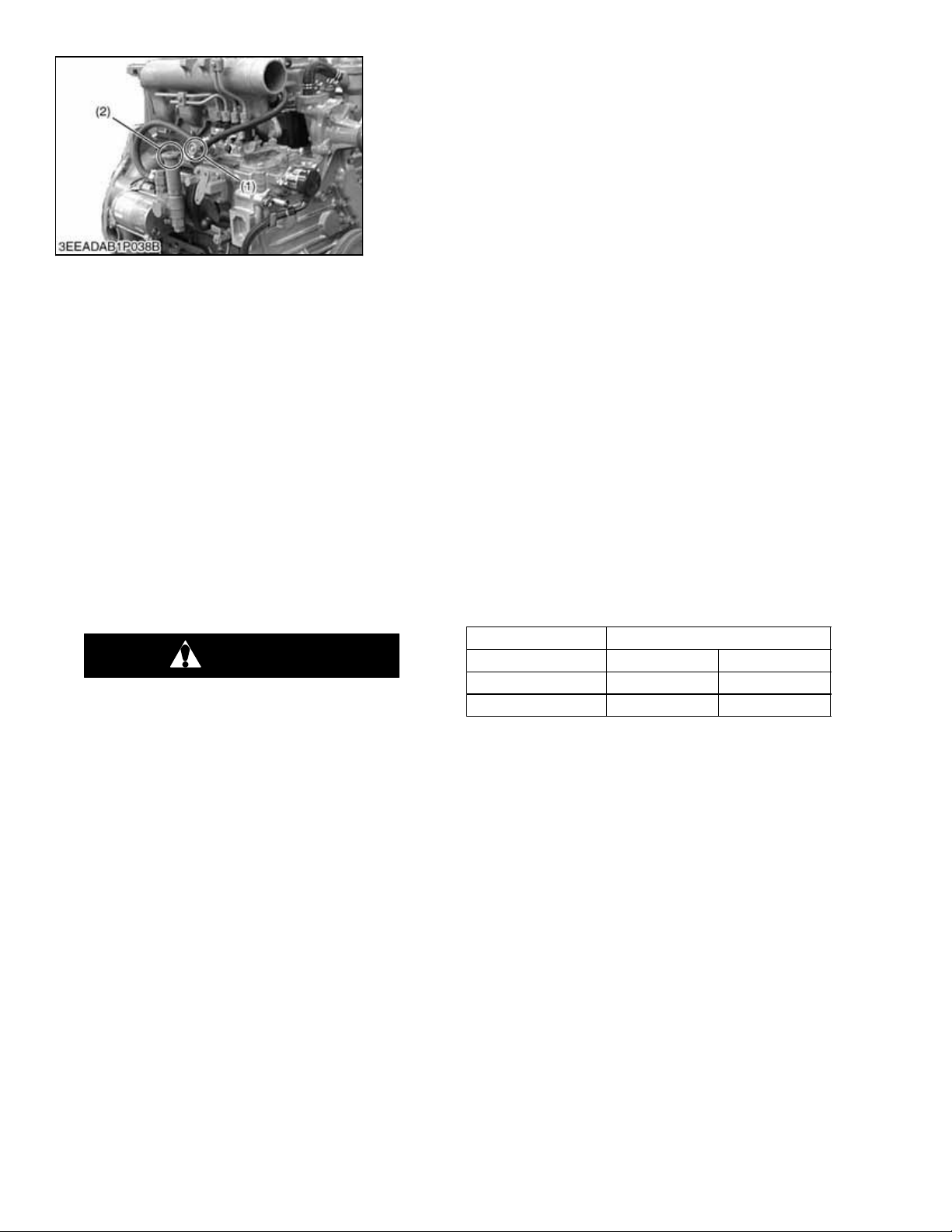
1.8.4 Bleeding Fuel System
1. Open the air vent cock (1) on top of the fuel injection
pump.
2. Loosen the priming pump handle (2), and pump the
handle until bleeding is completed.
3. Depress and twist the priming pump handle clock-
wisetolockintoplace.
4. Close the air vent cock (1).
NOTE
Always keep the air vent cock on the fuelinjec-
tionpumpclosed except when bleeding the fuel
system, or the engine may not run.
1.8.5 Checking V--Belt
Refer to Section 4.1
1.8.6 Changing Engine Oil
CAUTION
Stop the engine when preparing to change
the engine oil.
1. After warming up the engine, shut it off.
2. Place a pan underneath the engine.
3. Remove the drain plug, drain the engine oil
completely.
4. Inspect the drain plug gasket. Replace if necessary.
5. Reinstall the drain plug.
6. Replace the oil filter with a new oil filter.
7. Fill the crankcase with new oil.
8. Check for thecorrectoillevel.(RefertoSection1.8.1)
NOTE
When changing to a different oil manufacturer
or viscosity, be sure to remove all of the old oil
completely. Never mix different types of oil.
Use only API classification CG--4 or better oils.
Use the proper SAE engine oil according to the
ambient temperatures.
Above 25°C(77°F).............SAE 30 or10W--30
10W--40
0° to25°C(32° to77°F)......SAE20 or 10W--30
10W--40
Below0°C(32°F)............SAE10Wor10W--30
NOTE
With emission controls now in effect, theCG--4
or CH--4 / CI lubricating oils have been devel-
oped for use of a low--sulfur fuel on--road ve-
hicles engines. When an off--road vehicle en-
gine runs on a high--sulfur fuel, it is advisableto
employ the CH--4 / CI lubricating oil with a high
total base number. If the CG--4 lubricating oil is
usedwithahighsulfurfuel,changethelubricat-
ing oil at shorter intervals.
Lubricating oil recommended when a low--sulfur or
high--sulfur fuel is employed.
L
ubricating Oil Class Fuel
Low--sulfur High--sulfur
CG--4 O O
CH--4 or CI O X
O : Recommended X : Not Recommended
1--15 62--11362
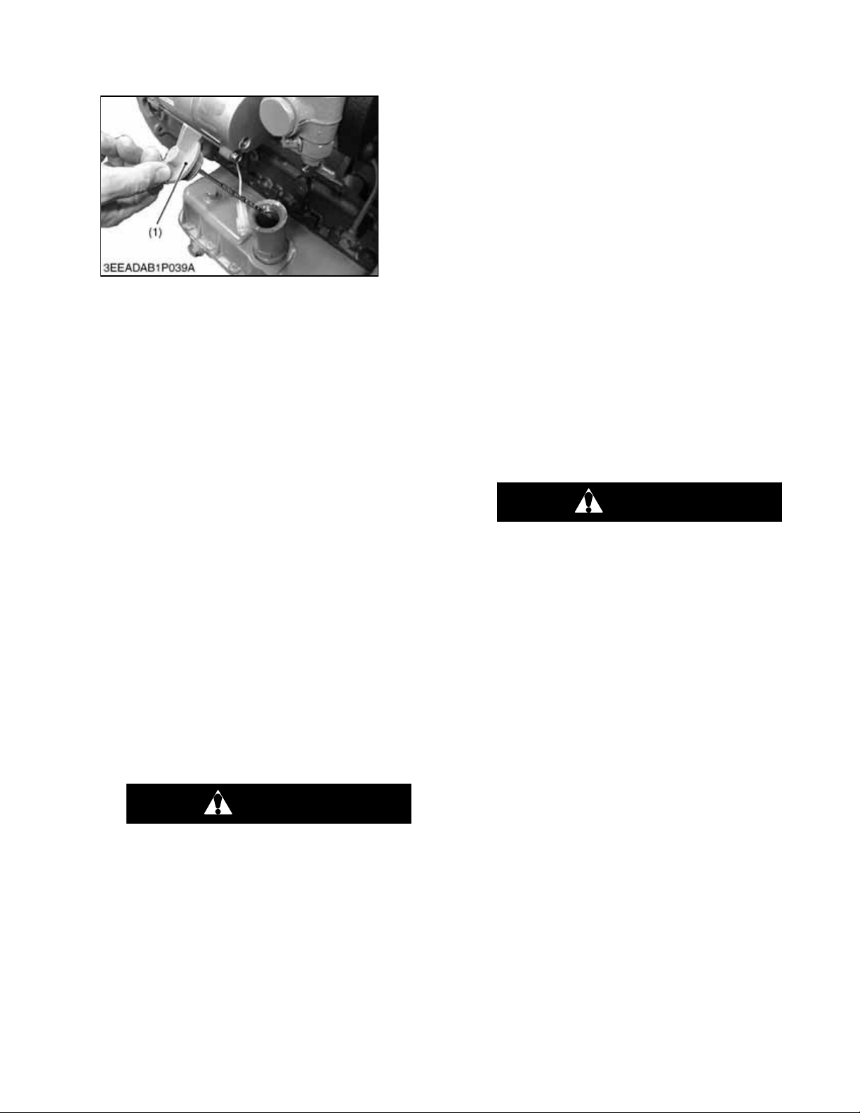
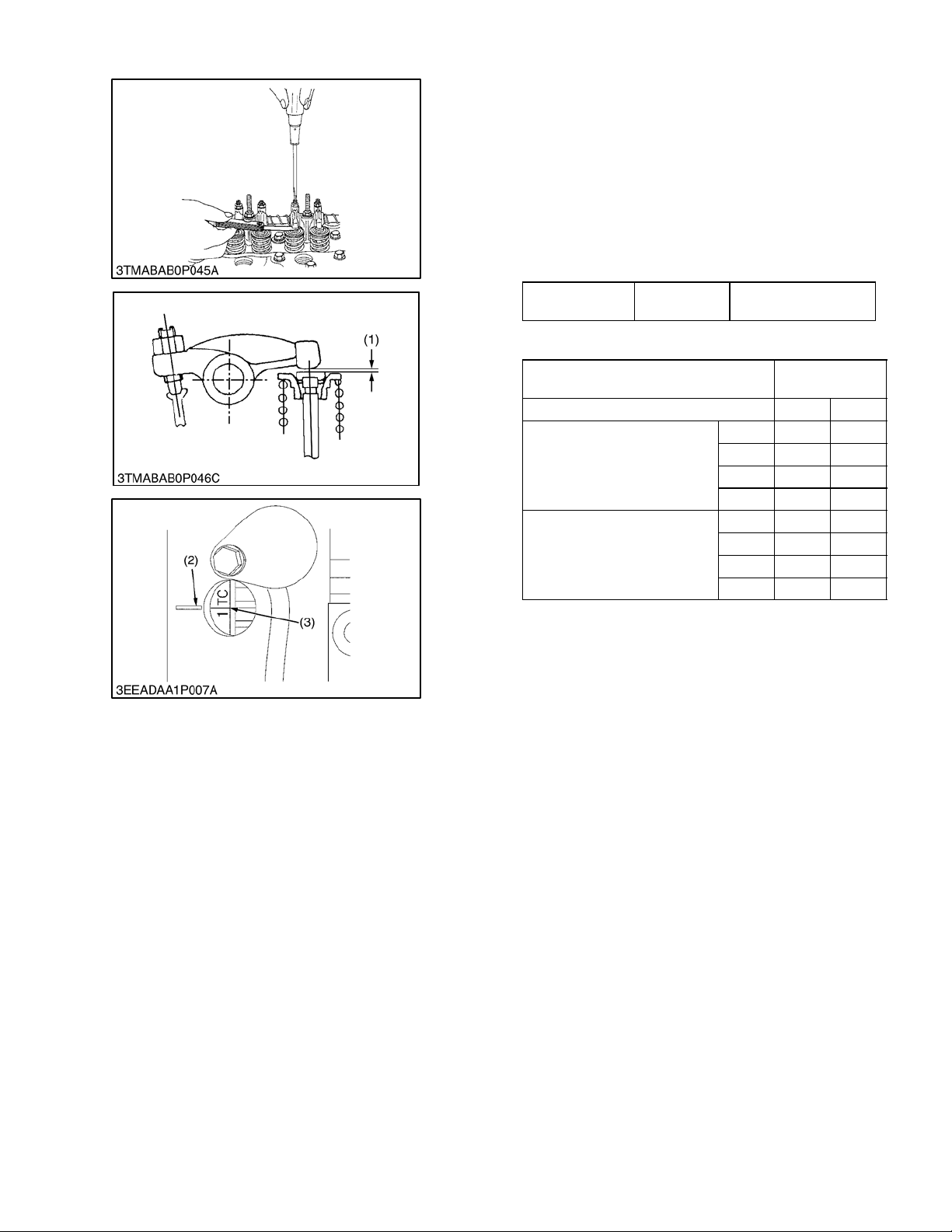
1.8.7 Valve Clearance
1.8.8 Fuel Injection
Refer to Section 5.2
NOTE
Valveclearancemust be checked and adjusted
when the engine is cold.
1. Remove the valve cover.
2. Align the“1TC” mark line (3)on the flywheel and pro-
jection (2) on the housing so that the Number 1piston
comes to compression or overlap top dead center
(TDC).
3. Check the following valve clearance (1) marked with
“*” using a feeler guage.
Valve Clearance
Factory
Specification
0.18 to 0.22 mm
0.0071 to 0.0086 in.
4. If the clearance is not within the factory specifica-
tions, adjust with the adjusting screw.
Valve
Arrangement
Piston Location in Cylinder IN. EX.
When No. 1 piston is at TDC
No. 1 * *
No. 2 *
No. 3 *
No. 4
When No. 1 piston is at past TDC
No. 1
No. 2 *
No. 3 *
No. 4 * *
 Loading...