


TP-PRH-A, TP-NRH-A
PerformancetSeries
Edger Thermidistatt Control
Installation Instructions
A07049 |
A07048 |
Programmable Control |
Non−Programmable Control |
|
Designed and Assembled |
|
in the USA. |
NOTE: Read the entire instruction manual before starting the installation.
US patents: US7287709 B2, US20080147242 A1, USD582800 SI, US20060165149 A1, US6956463 B2.
TABLE OF CONTENTS
PAGE SAFETY CONSIDERATIONS . . . . . . . . . . . . . . . . . . . . . . . . . . . . . . . . . . . . 2 INTRODUCTION . . . . . . . . . . . . . . . . . . . . . . . . . . . . . . . . . . . . . . . . . . . . . . 3 INSTALLATION CONSIDERATIONS . . . . . . . . . . . . . . . . . . . . . . . . . . . . . . 4 INSTALLATION . . . . . . . . . . . . . . . . . . . . . . . . . . . . . . . . . . . . . . . . . . . . . . . 8 SYSTEM START−UP AND CHECKOUT . . . . . . . . . . . . . . . . . . . . . . . . . . 44 OPERATIONAL INFORMATION . . . . . . . . . . . . . . . . . . . . . . . . . . . . . . . . 55 TROUBLESHOOTING . . . . . . . . . . . . . . . . . . . . . . . . . . . . . . . . . . . . . . . . . 59 WIRING DIAGRAMS . . . . . . . . . . . . . . . . . . . . . . . . . . . . . . . . . . . . . . . . . . 63 THERMIDISTAT CONTROL CONFIGURATION RECORD . . . . . . . . . . . 84
SAFETY CONSIDERATIONS
Read and follow manufacturer instructions carefully. Follow all local electrical codes during installation. All wiring must conform to local and national electrical codes. Improper wiring or installation may damage Thermidistat Control.
Recognize safety information. This is the safety−alert symbol  . When you see this symbol on the equipment and in the instruction manual, be alert to the potential for personal injury.
Understand the signal words DANGER, WARNING, and CAUTION. These words are used with the safety−alert symbol. DANGER identifies the most serious hazards which will result in severe personal injury or death. WARNING signifies a hazard which could result in personal injury or death. CAUTION is used to identify unsafe practices which may result in minor personal injury or product and property damage. NOTE is used to highlight suggestions which will result in enhanced installation, reliability, or operation.
2
INTRODUCTION
Carrier’s 7−day, 5/2−day, 1−day programmable and non−programmable Performance Series Thermidistat Control is a wall−mounted, low−voltage control which combines temperature and humidity control in either a single unit or a two−piece unit. In two−piece configuration, the relays are located near the equipment and a two−wire connection is used between the Display Module and the Equipment Control Module. Single−piece installation requires more wiring and results in a higher profile. The Edger Thermidistat has no need for batteries to store user−configured settings in memory. During power loss its internal memory saves settings for unlimited time, and the clock continues to run for at least 24 hours. An extension of Carrier’s proven line of thermostats; it provides separate setpoints for heating and cooling in addition to humidification and dehumidification.
In the Edge Thermidistat Control programmable configuration, different heating and cooling setpoints and times are programmable for 4 periods per day or 2 periods per day. Programming can be done for 7 days per week, 5/2 days per week, or 1 day. The programmable Thermidistat Control can also be user configured as a non−programmable Thermidistat Control. When operating as non−programmable, the Edge Thermidistat Control will still have both temperature and humidity control.
The non−programmable Thermidistat Control features Touch ’N’ Got settings for quick and easy temperature change without complicated programming schedules. The non−programmable Edge Thermidistat Control will still have both temperature and humidity control. And, its Touch ’N’ Go technology enables the user to switch between three different user−configurable settings through intuitive buttons located just below the display.
3
INSTALLATION CONSIDERATIONS
Power
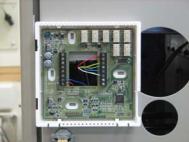
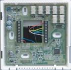
This control is powered by 24VAC only. It requires 24VAC (Rh and/or Rc and C terminals) of the low−voltage transformer to be connected to it for proper operation. It will not operate without these 2 connections. Rh and Rc are connected via PCB breakout jumper. See Fig. 1. For applications using two 24VAC transformers, one in the indoor unit and one in the outdoor unit, connect the common from each to the C terminal. Connect R from the indoor unit to the Rh terminal. Connect R from the outdoor unit to the Rc terminal. Then, break jumper on the circuit board. The W and HUM signals are taken from the Rh power and the G signal is taken from the Rc power. If Thermidistat Control has been installed in a two−transformer application that is later changed to a single−transformer installation, installer must install a field supplied jumper between Rc and Rh. Depending on the installation, up to 14 wires may be required. Installation as two−piece unit is recommended. Only 2 wires are required for connection between Display Module and Equipment Control Module. These two wires (V+ and Vg) do not provide ordinary 24VAC. They carry a combination of power and communications data that is unique to these products.
4

A07052
Fig. 1 − PCB Breakout Jumper
Models
There are programmable and non−programmable models for all applications. They can be configured for AC or HP, 1−or 2−speed compressor, and for Hybrid Heatt installations, allowing it to be used in place of all Carrier thermostats. Programmable Thermidistat Controls may be configured as non−programmable if user desires.
Humidify Equipment and Connections
The humidify output connects directly to 24VAC operated humidifiers. An isolation relay may be required when using powered humidifiers. No other connection or interlock is required. Any of several installer−selectable operating modes are available.
5

!WARNING
ELECTRICAL OPERATION HAZARD
Failure to follow this warning could result in personal injury or death.
DO NOT connect furnace HUM terminal directly to Thermidistat Control HUM terminal. This will bypass furnace safety controls. See Low Voltage Wiring Diagrams and notes for proper connection.
Dehumidify Equipment and Connections
The dry contact output connects to the dehumidify input on variable−speed furnaces and fan coils. Additional dehumidification is done by controlling the compressor. A variety of operating modes are available. The dry contact must be configured for dehumidification in setup Option 19. See Wiring Diagrams for more information.
Outdoor Temperature Sensor (TSTATCCSEN01−B)
Outdoor air temperature sensor is included in the box with the Thermidistat Control. Optimum performance is obtained when an outdoor temperature sensor is used with the Thermidistat Control. Plan installation so that 2 wires can be run from Equipment Control Module to an outdoor location, preferably on the north side of the house or refer to Installation Instructions included with the outdoor temperature sensor for simplified connection. Sensor can be mounted to outdoor unit and existing control wires may be used for its connection. Details are provided in sensor instructions.
6
Remote Indoor Temperature Sensor
A remote temperature sensor may be used with the programmable model, where it is desirable to install the Thermidistat Control in a limited access location while measuring the temperature in the living space. The remote room sensor may be used as a stand alone or average with local sensor.
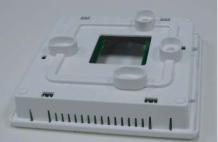
Two−Piece Thermidistat Control Configuration
The Performance Series Thermidistat Control can be installed in one of two configurations. The control may be installed as a single−piece Thermidistat Control or it may be split into two pieces and mounted in separate locations. As a single−piece unit, all required wiring must be brought to the Equipment Control Module for connection to the terminal strip. In two−piece configuration, the Display Module can be mounted in the living space while the Equipment Control Module may be mounted near the indoor furnace or fan coil. Connection from the Display Module to the Equipment Control Module requires only two wires. All other control wires are connected to the Equipment Control Module from the HVAC equipment. This configuration results in a slimmer display and locates the Equipment Control Module containing the switching relays away from the main living space where relay clicking will not be heard.
The model numbers on the Display Module and the Equipment Control Module (ECM) must match or unpredictable results may occur.
Two−wire pigtail replacement part number is TX−2WR05.
Wiring
Wire length should be no more than 250 ft (76 m). Use 22 AWG or larger for normal wiring applications. Continuous wire lengths over 100 ft (30.5 m) should use 20 AWG or larger.
7
INSTALLATION
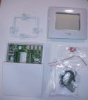
Carton contains the following components. See Fig. 2 for TP−PRH−A or Fig. 3 for TP−NRH−A.
A07685
Fig. 2 − TP−PRH−A Carton Contents
1.Display Module
2.Stand−off for Equipment Control Module
3.Outside Air Temperature Sensor, screws and pigtail
4.Equipment Control Module
8
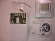
A07686
Fig. 3 − TP−NRH−A Carton Contents
1.Display Module
2.Stand−off for Equipment Control Module
3.Outside Air Temperature Sensor, screws and pigtail
4.Equipment Control Module
Thermidistat Control Location
Thermidistat Control should be mounted:
SApproximately 5 ft (1.5m) from floor.
SClose to or in a frequently used room, preferably on an inside partitioning wall.
SOn a section of wall without pipes or duct work. Thermidistat Control should NOT be mounted:
SClose to a window, on an outside wall, or next to a door leading to the outside.
9
SExposed to direct light or heat from a lamp, sun, fireplace, or other temperature−radiating objects which could cause a false reading.
SClose to or in direct airflow from supply registers and return−air registers.
SIn areas with poor air circulation, such as behind a door or in an alcove.
Installer should determine whether control will be installed as single−piece or two−piece. In single−piece configuration, as many as 14 wires may need to run to wall mounting location for connection to the control. In two−piece configuration, the Display Module and Equipment Control Module are connected by two wires.
Install Thermidistat Control
!WARNING
ELECTRICAL OPERATION HAZARD
Failure to follow this warning could result in personal injury or death.
Before installing Thermidistat Control, turn off all power to equipment. There may be more than 1 power disconnect.
10
!CAUTION
UNIT DAMAGE HAZARD
Failure to follow this caution may result in equipment damage or improper operation.
Improper wiring or installation may damage Thermidistat Control. Check to make sure wiring is correct before proceeding with installation or turning on power.
1.Turn off all power to equipment.
2.If an existing Thermidistat Control or thermostat is being replaced:
a.Remove existing control from wall.
b.Disconnect wires from existing thermostat, 1 at a time.
c.As each wire is disconnected, record wire color and terminal marking.
d.New or additional wires may be needed to accommodate added humidity outputs.
e.Discard or recycle old control.
11
!CAUTION
ENVIRONMENTAL HAZARD
Failure to follow this caution may result in environmental damage.
Mercury is a hazardous waste. Federal regulations require that Mercury be disposed of properly.
Two−Piece Installation
The following steps should be followed for the installation of the two−piece configuration.
NOTE: The 2−wire pigtail is not intended to support the weight of the Display Module. Do not hang the Display Module from the Equipment Control Module screw terminals.
1.Remove mounting plate from back of Display Module by pressing the two tabs on the bottom edge and pulling away. See Fig. 4 and 5.
12
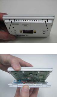
A07225
Fig. 4 − Press Tabs to Remove Backplate
A07226
Fig. 5 − Take Apart
13
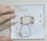
2.Route wires through large hole in mounting base. Level mounting base against wall (for aesthetic value only—Display Module need not be leveled for proper operation) and mark wall through 4 mounting holes. To avoid unintended bending of wall plate plastic, use all 4 screws and anchors. See Fig. 6.
A07165
Fig. 6 − Backplate Mounting
3.Drill four 3/16−in. mounting holes in wall where marked. Thermidistat Control may be mounted to a standard junction box, if desired. Hole pattern on Thermidistat Control mounting base matches junction box mounting holes.
4.Secure rear plastic mounting base to wall with 4 screws and anchors provided. To avoid unintended bending of wall plate plastic, use all 4 screws and anchors. Make sure all wires extend through hole in mounting base.
5.Adjust length and routing of each wire to reach proper connector block and terminal on mounting base with 1/4−in. (6 mm) extra wire.
14

6.Match and connect equipment wires to proper terminals of each connector block, being careful not to over tighten the screws. Correct polarity must be observed when connecting the two wires from the Equipment Control Module to the Thermidistat Control mounting base. If wires are connected incorrectly, the Display Module will not operate. See Fig. 7, 8 and 9.
A08072
Fig. 7 − Control Module Wiring Guide
SRed is V+
SBlack is Vg
15
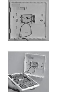
A07166
Fig. 8 − Secure Wires to Terminal Strip
A07167
Fig. 9 − Connect Pigtail Wires to Display Module
16
NOTE: The 2−wire pigtail is not intended to support the weight of the Display Module. Do not hang the Display Module from the Equipment Control Module screw terminals.
SRed of the pigtail is V+
SBlack of the pigtail is Vg
7.Push any excess wire into wall and against mounting base. Seal hole in wall to prevent air leaks. Leaks can affect operation and cause incorrect temperature and/or humidity measurement.
8.Make sure to attach 2−wire pigtail to Display Module mounting base. It is packed loose in the box from the factory. Then attach 2−wire pigtail to the back of the Display Module via 2 pin, keyed connector.
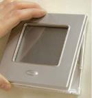
9.Reattach Display Module body to mounting base by first setting on at top of mounting base and then push bottom corners of Display Module to snap into place. See Fig. 10.
A07168
Fig. 10 − Attach Display to Backplate
17
10.Find suitable indoor mounting location for Equipment Control Module, either near or on equipment. See Fig. 11.
IMPORTANT NOTE: Equipment Control Module should not be mounted to duct work or below any other controls or equipment (i.e. humidistat, humidifier, etc.).
A07217
Fig. 11 − Equipment Control Module on Equipment
11.Route wires through rear of Equipment Control Module using either a clearance hole or supplied standoff. See Fig. 12.
18
A07227
Fig. 12 − Standoff
NOTE: Standoffs are provided as an aid when installing Equipment Control Module on inside equipment or a solid wall.
12.Match and connect equipment wires to proper terminals of each connector block being careful not to over tighten the screws. Correct polarity must be observed when connecting the two wires from the Equipment Control Module to the Thermidistat Control mounting base. If wires are connected incorrectly, the Display Module will not operate. See Fig. 7, 8 and 9.
13.Snap cover over top of Equipment Control Module. See Fig. 13.
19
A07218
Fig. 13 − Cover on Equipment Control Module
14.Turn on power to equipment. On power up, all display segments will light for 5 sec. For the next 5 sec a 2−digit code appears on large display which identifies Thermidistat Control configuration. Refer to Option 33.
a.AC — 1−stage air conditioner with furnace or fan coil
b.HP — 1−stage heat pump with fan coil
c.A2 — 2−stage air conditioner with furnace or fan coil
d.H2 — 2−stage heat pump with fan coil
e.hh — Hybrid Heat system with 1−stage heat pump
f.h2 — Hybrid Heat system with 2−stage heat pump
g.H — heating only system
h.C — cooling only system
20
Single−Piece Installation
The following steps should be followed for the installation of the single−piece configuration.
1.Remove cover from Equipment Control Module by pressing the two tabs on the bottom edge and pulling away. Route wires through large hole in Equipment Control Module. Level Equipment Control Module against wall (for aesthetic value only − Equipment Control Module need not be leveled for proper operation) and mark wall through 4 mounting holes.
2.Drill two 3/16−in. mounting holes in wall where marked. Thermidistat Control may be mounted to a standard junction box if desired. Hole pattern on Equipment Control Module matches junction box mounting holes.
3.Secure rear plastic Equipment Control Module to wall with 4 screws and anchors provided. To avoid unintended bending of wall plate plastic, use all 4 screws and anchors. Make sure all wires extend through hole in Equipment Control Module.
4.Adjust length and routing of each wire to reach proper connector block and terminal on Equipment Control Module with 1/4−in. (6 mm) extra length. See Fig. 14.
21
A07219
Fig. 14 − Equipment Control Module
5.Match and connect equipment wires to proper terminals of each connector block.
6.Push any excess wire into wall and against Equipment Control Module. Seal hole in wall to prevent air leaks. Leaks can affect operation and cause incorrect temperature and/or humidity measurement.
7.Attach 2−wire pigtail to Equipment Control Module terminal block (terminals V+ and Vg). Attach 2−wire pigtail to the back of the Display Module via 2 pin, keyed connector.
8.Reattach Display Module body to Equipment Control Module by first setting on at top and then push bottom corners to snap into place. See Fig. 15.
22

A07220
Fig. 15 − Reattach Display Module
9.Turn on power to equipment. On power up, all display segments will light for 5 sec. For the next 5 sec a 2−digit code appears on large display which identifies Thermidistat Control configuration. Refer to Option 33.
a.AC — 1−stage air conditioner with furnace or fan coil
b.HP — 1−stage heat pump with fan coil
c.A2 — 2−stage air conditioner with furnace or fan coil
d.H2 — 2−stage heat pump with fan coil
e.hh — Hybrid Heat system with 1−stage heat pump
f.h2 — Hybrid Heat system with 2−stage heat pump
g.H — heating only system
h.C — cooling only system
23
Set Thermidistat Control Configuration
Configuration options enable the installer to configure the Thermidistat Control for a particular installation. Most are not presented to the homeowner and therefore must be properly set by the installer. (Only those marked with an asterisk * below are available to the homeowner.) The homeowner configurations are described in the owner’s manual. A special procedure allows entry into the configuration mode. Selections can be made while in configuration mode. Description of each selection and how to use the configuration mode follows.
CONFIGURATION OPTIONS − SUMMARY Option 01 — Equipment Type
Option 02 — Clean Filter Timer Adjustment
Option 03* — Fahrenheit/Centigrade Selection Option 04 — Fan (G) on with W/W1 Selection
Option 05 — Room Air Temperature Sensing (programmable models only)
Option 06 — Cooling Lockout Below 55_F/13_C Selection (only available if outdoor air sensor is present)
Option 07 — Zoning
Option 08 — Auxiliary Heat Lockout Temperature Setting (only available when heat pump is used and when outdoor air temperature sensor is present)
Option 09 — Heat Pump Lockout Temperature Balance Point (only available when outdoor air temperature sensor is present)
Option 10 — Reversing Valve
24
Option 11 — |
Adjustable Setpoint Deadband (not available on |
|
heat only and cool only systems) |
Option 12 — |
Smart Recovery (programmable models only) |
Option 13 — |
Room Temperature Offset Adjustment |
Option 14 — |
Humidity Offset Adjustment |
Option 15 — |
Enable Auto Mode |
Option 16 — |
Cycles Per Hour |
Option 17 — |
Time Between Stages |
Option 18* — |
Backlight Configuration |
Option 19 — |
Dry Contact |
Option 20 — |
Outdoor Air Temperature Offset Adjustment |
Option 21* — |
Keypad Lockout |
Option 22 — |
High Cool Latch Temperature |
Option 23 — |
High Heat Latch Temperature |
Option 24* — |
Programmable/Non−Programmable |
|
(programmable models only) |
Option 25* — |
Number of Programmable Periods per Day |
|
(programmable models only) |
Option 26 — |
Minimum Cooling Setpoint |
Option 27 — |
Maximum heating Setpoint |
Option 28 — |
UV Light Reminder |
Option 29 — |
Humidifier Pad Reminder |
Option 30* — |
Programmable Fan (programmable models only) |
25
Option 31* — Daylight Savings Time Configuration (programmable models only)
Option 32 — Furnace Heat Staging
Option 33 — Single or Two−Piece Installation Option 34 — Hybrid Heat Furnace Latch Option 40 — Fan Humidify
Option 41 — Variable Speed Blower
Option 42 — Variable Speed Super Dehumidification Option 43 — Intelligent Heat Staging
Option 44 — Super Comfort Heat Option 99 — Reset to Factory Defaults TO ENTER CONFIGURATION MODE
Press and hold FAN button for approximately 10 sec. The Display Module is now in configuration mode. It will automatically exit this mode if no button is pressed for 3 minutes. Pressing the DONE button will exit configuration mode immediately.
WHILE IN CONFIGURATION MODE
The option number is displayed in the heat setpoint location and the configuration setting is displayed in the cool setpoint location. On the TP−PRH−A (programmable) model, a box will surround the option number. The mode button is used to move the box between the two displayed values. The soft keys below the listed values may also be used to move the box between selected values. The value inside the box is changed by using the UP/DOWN buttons. On the TP−NRH−A (non−programmable) model, one of the values will be flashing. The mode button is used to change which value is flashing or the Home and Sleep buttons may also be used to select which value to flash. The value that is
26
flashing is changed by using the UP/DOWN buttons. All changes made are saved at the time of selection and will be saved in the event of the 3 minute time−out or when installer exits from configuration menu.
Configuration Options —Selection
Option 01 — Equipment Type
Range: H2, A2, HP, AC, hh, h2, H, C
H2 — operates a two−speed heat pump with a fan coil HP — operates a single−speed heat pump with a fan coil A2 — operates a two−speed AC with a fan coil or furnace
AC — operates a single−speed AC with a fan coil or furnace hh — operates a single−speed heat pump with a furnace
h2 — operates a two−speed heat pump with a furnace
H— operates a heat−only system. Furnace or fan coil only; no outdoor unit.
C— operates a cool only−system. Outdoor AC unit with an indoor fan coil with no strip heaters.
Default is H2.
Option 02 — Clean Filter Timer
Select hours of blower operation (heating, cooling, or fan) before CHECK FILTER icon is displayed. With OF selected, icon will never come on, disabling this feature. Time selection can range from 800 to 7200 hr by selecting numbers 1 through 9. (Time is 800 X number selected.) Default is 4 (3200 hr).
Recommended selections are disposable filter−800 to 2400 hr, media filter−2400 to 3200 hr, or electronic air cleaner−1600 to 2400 hr of blower operation. For higher efficiency filter, please consult filter’s Installation Instruction for details.
27
 Loading...