


48TJE,TJF004 48TJD,TJE,TJF005-007 Single-Package Rooftop Heating/Cooling Units
Installation, Start-Up and
Service Instructions
CONTENTS
Page
SAFETY CONSIDERATIONS . . . . . . . . . . . . . . . . . . . . . . 1
INSTALLATION . . . . . . . . . . . . . . . . . . . . . . . . . . . . . . . . 1-36
Step 1 — Provide Unit Support . . . . . . . . . . . . . . . . . . . 1
•ROOF CURB
•SLAB MOUNT
Step 2 — Field Fabricate Ductwork . . . . . . . . . . . . . . . 2
Step 3 — Install External Trap for
Condensate Drain . . . . . . . . . . . . . . . . . . . . . . . . . . . . . . 2 Step 4 — Rig and Place Unit . . . . . . . . . . . . . . . . . . . . . 2
• POSITIONING |
|
|
Step 5 |
— Install Flue Hood . . . . . . . . . . . . . . . . . . . . . . . |
4 |
Step 6 |
— Install Gas Piping . . . . . . . . . . . . . . . . . . . . . . |
4 |
Step 7 |
— Make Electrical Connections . . . . . . . . . . . |
5 |
•DISCONNECT BOX LOCATION
•FIELD POWER SUPPLY
•FIELD CONTROL WIRING
•HEAT ANTICIPATOR SETTINGS
Step 8 — Make Outdoor-Air Adjustment and
Install Outdoor-Air Hood . . . . . . . . . . . . . . . . . . . . . . 12
•MANUAL OUTDOOR-AIR DAMPER
•OPTIONAL DURABLADE ECONOMIZER
•OPTIONAL ECONOMI$ER
Step 9 — Adjust Evaporator-Fan Speed . . . . . . . . . 20
•DIRECT-DRIVE MOTORS
•BELT-DRIVE MOTORS
START-UP . . . . . . . . . . . . . . . . . . . . . . . . . . . . . . . . . . . . 37-39 SERVICE . . . . . . . . . . . . . . . . . . . . . . . . . . . . . . . . . . . . . 40-44 TROUBLESHOOTING. . . . . . . . . . . . . . . . . . . . . . . . . 45-50 START-UP CHECKLIST . . . . . . . . . . . . . . . . . . . . . . . . CL-1
SAFETY CONSIDERATIONS
Installation and servicing of air-conditioning equipment can be hazardous due to system pressure and electrical components. Only trained and qualified service personnel should install, repair, or service air-conditioning equipment.
Untrained personnel can perform basic maintenance functions of cleaning coils and filters and replacing filters. All other operations should be performed by trained service personnel. When working on air-conditioning equipment, observe precautions in the literature, tags and labels attached to the unit, and other safety precautions that apply.
Follow all safety codes. Wear safety glasses and work gloves. Use quenching cloth for unbrazing operations. Have fire extinguishers available for all brazing operations.
Ensure voltage listed on unit data plate agrees with electrical supply provided for the unit.
Disconnect gas piping from unit when leak testing at pressure greater than 1/2 psig. Pressures greater than 1/2 psig will cause gas valve damage resulting in hazardous condition. If gas valve is subjected to pressure greater than 1/2 psig, it must be replaced before use. When pressure testing field-supplied gas piping at pressures of 1/2 psig or less, a unit connected to such piping must be isolated by manually closing the gas valve.
Before performing service or maintenance operations on unit, turn off main power switch to unit and install lockout tag. Electrical shock could cause personal injury.
INSTALLATION
Unit is shipped in the vertical discharge configuration. To convert to horizontal configuration, remove screws from side duct opening covers and remove covers. Using the same screws, install covers on vertical duct openings with the insulation side down. Seals around duct openings must be tight. See Fig. 1.
Step 1 — Provide Unit Support
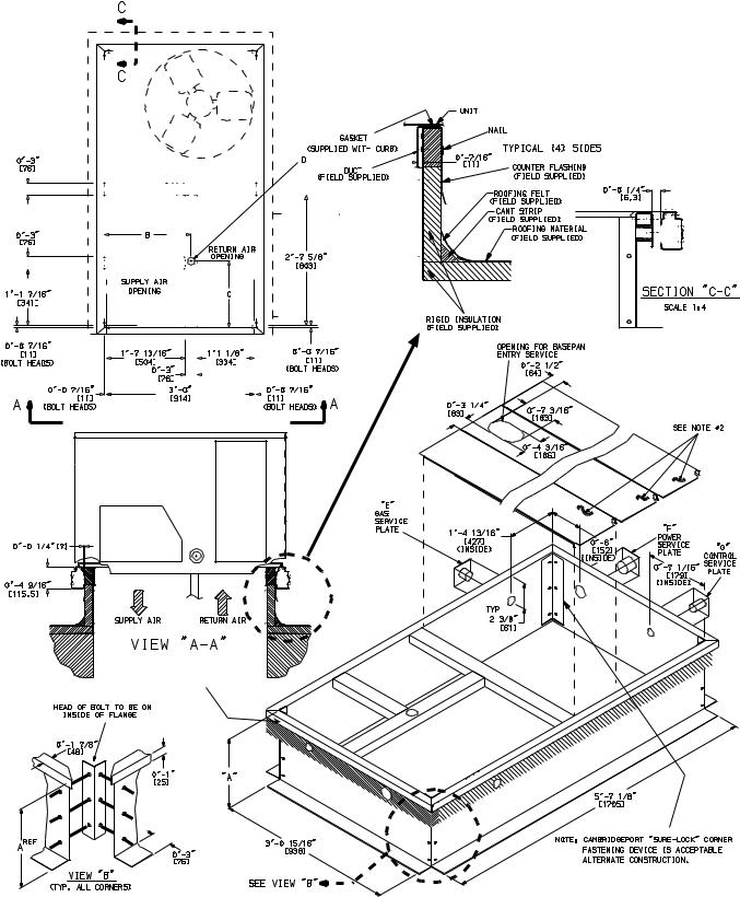
ROOF CURB — Assemble and install accessory roof curb in accordance with instructions shipped with curb. See Fig. 2. Install insulation, cant strips, roofing felt, and counter flashing as shown. Ductwork must be attached to curb, not to the unit. The accessory thru-the-bottom power and gas connection package must be installed before the unit is set on the roof curb. If fieldinstalled (thru-the-roof curb) gas connections are desired, use factory-supplied 3/4 in. pipe coupling and gas plate assembly to mount the thru-the-roof curb connection to the roof curb. Gas connections and power connections to the unit must be field installed after the unit is installed on the roof curb.
If electric and control wiring is to be routed through the basepan, attach the accessory thru-the-bottom service connections to the basepan in accordance with the accessory installation instructions.
IMPORTANT: The gasketing of the unit to the roof curb is critical for a watertight seal. Install gasket supplied with the roof curb as shown in Fig. 2. Improperly applied gasket can also result in air or water leaks and poor unit performance.
Manufacturer reserves the right to discontinue, or change at any time, specifications or designs without notice and without incurring obligations.
Book |
1 |
4 |
PC 111 |
Catalog No. 534-774 |
Printed in U.S.A. |
Form 48TJ-18SI |
Pg 1 |
10-00 |
Replaces: 48TJ-16SI |
Tab |
1a |
6a |
|
|
|
|
|
|
|
|
|
|
|
|
|
|
|
|
|

Fig. 1 — Horizontal Conversion Panels
(Viewed from Duct End)
Curb should be level. Unit leveling tolerances are shown in Fig. 3. This is necessary for unit drain to function properly. Refer to Accessory Roof Curb Installation Instructions for additional information as required.
SLAB MOUNT (Horizontal Units Only) — Provide a level concrete slab that extends a minimum of 6 in. beyond unit cabinet. Install a gravel apron in front of condenser coil air inlet to prevent grass and foliage from obstructing airflow.
NOTE: Horizontal units may be installed on a roof curb if required.
Step 2 — Field Fabricate Ductwork — Secure all ducts to roof curb and building structure on vertical units. Do not connect ductwork to unit. For horizontal applications, fieldsupplied flanges should be attached to horizontal discharge openings and all ductwork should be secured to the flanges. Insulate and weatherproof all external ductwork, joints, and roof openings with counter flashing and mastic in accordance with applicable codes.
Ducts passing through an unconditioned space must be insulated and covered with a vapor barrier.
If a plenum return is used on a vertical unit, the return should be ducted through the roof deck to comply with applicable fire codes.
A minimum clearance is not required around ductwork. Cabinet return air static shall not exceed –.30 in. wg with EconoMi$er, or –.35 in. wg with Durablade Economizer, or –.45 in. wg without economizer.
These units are designed for a minimum continuous returnair temperature of 50 F (dry bulb), or an intermittent operation down to 45 F (dry bulb) (in heating mode), such as when used with a night set-back thermostat.
Step 3 — Install External Trap for Condensate Drain — The unit’s 3/4-in. condensate drain connections are located on the bottom and side of the unit. Unit discharge connections do not determine the use of drain connections; either drain connection can be used with vertical or horizontal applications.
When using the standard side drain connection, make sure the plug (Red) in the alternate bottom connection is tight before installing the unit.
To use the bottom drain connection for a roof curb installation, relocate the factory-installed plug (Red) from the bottom connection to the side connection. See Fig. 4. The piping for the condensate drain and external trap can be completed after the unit is in place.
All units must have an external trap for condensate drainage. Install a trap at least 4-in. deep and protect against freezeup. If drain line is installed downstream from the external trap, pitch the line away from the unit at 1 in. per 10 ft of run. Do not use a pipe size smaller than the unit connection (3/4 in.).
Step 4 — Rig and Place Unit — Inspect unit for transportation damage. File any claim with transportation agency. Keep unit upright and do not drop. Spreader bars are not required if top crating is left on unit. Rollers may be used to move unit across a roof. Level by using unit frame as a reference. See Table 1 and Fig. 5 for additional information.
Lifting holes are provided in base rails as shown in Fig. 6. Refer to rigging instructions on unit.
All panels must be in place when rigging and lifting.
2
‘‘B’’ |
‘‘C’’ |
|
‘‘D’’ ALT |
|
|
|
‘‘E’’ |
|
|
“F” |
|
|
|
“G” |
|
|
|
|
|
CONNECTOR |
|
||||||||||||||||||||||||||||||||||||||||
DRAIN HOLE |
|
|
|
Gas |
|
Power |
|
|
|
Control |
|
|
|
|
|
|
PKG ACY |
|
|||||||||||||||||||||||||||||||||||||||||||
|
|
|
|
|
|
|
|
|
|
|
|
|
|
|
|
|
|
|
|
|
|||||||||||||||||||||||||||||||||||||||||
|
|
|
|
|
|
|
|
|
|
|
|
|
|
|
|
|
|
|
|
|
|
|
|
|
|
|
3/4″ |
|
|
|
|
|
|
|
|
|
|
|
|
|
|
CRBTMPWR001A00 |
|
||||||||||||||||||
|
|
|
|
|
|
|
|
|
|
|
|
|
|
|
|
|
|
|
3/4″ |
|
[19] NPT |
|
|
|
|
|
|
|
|
|
|
|
|
|
|
|
|||||||||||||||||||||||||
|
|
|
|
|
|
|
|
|
|
|
|
|
|
|
|
|
|
|
|
|
|
|
|
|
|
|
|
|
|
|
|
|
|
|
|
|
|
|
|
|
|
|
|
|
|
|
|
|
|
||||||||||||
|
|
|
|
|
|
|
|
|
|
|
|
|
|
|
|
|
[19] NPT |
|
11/4″ |
|
|
|
|
|
|
|
|
|
|
|
|
|
|
CRBTMPWR002A00 |
|
||||||||||||||||||||||||||
1′-911/16″ |
1′-4″ |
|
|
|
13/4″ |
|
|
|
|
|
|
|
|
|
|
[31.7] |
|
|
|
|
1/2″ |
|
|
||||||||||||||||||||||||||||||||||||||
|
|
|
|
|
|
|
|
|
|
|
|
|
|
|
|
|
|
|
|
|
|
|
|
|
|
|
|
|
|
|
|
|
|
||||||||||||||||||||||||||||
[551] |
|
|
[406] |
[44.5] |
|
|
|
|
|
1/2″ |
|
|
3/4″ |
|
[12.7] NPT |
|
CRBTMPWR003A00 |
|
|||||||||||||||||||||||||||||||||||||||||||
|
|
|
|
|
|
|
|
|
|
|
|
|
|
|
|
|
[12.7] NPT |
|
[19] NPT |
|
|
|
|
|
|
|
|
|
|
|
|
|
|
|
|||||||||||||||||||||||||||
|
|
|
|
|
|
|
|
|
|
|
|
|
|
|
|
|
|
|
|
|
|
|
|
|
|
|
|
|
|
|
|
|
|
|
|
|
|
|
|
|
|
|
|
|
|
|
|
||||||||||||||
|
|
|
|
|
|
|
|
|
|
|
|
|
|
|
|
|
|
|
3/4″ |
|
11/4″ |
|
|
|
|
|
|
|
|
|
|
|
|
|
|
CRBTMPWR004A00 |
|
||||||||||||||||||||||||
|
|
|
|
|
|
|
|
|
|
|
|
|
|
|
|
|
[19] NPT |
|
[31.7] |
|
|
|
|
|
|
|
|
|
|
|
|
|
|
|
|
||||||||||||||||||||||||||
|
|
|
|
|
|
|
|
|
|
|
|
|
|
|
|
|
|
|
|
|
|
|
|
|
|
|
|
|
|
|
|
|
|
|
|
|
|
|
|
|
|
|
|
|
|
|
|
|
|||||||||||||
|
|
|
|
|
|
|
|
|
|
|
|
|
|
|
|
|
|
|
|
|
|
|
|
|
|
|
|
|
|
|
|
|
|
|
|
|
|
|
|
|
|
|
|
|
|
|
|
|
|
|
|
|
|
|
|
|
|
|
|
|
|
|
|
|
|
|
|
|
|
|
|
|
|
|
|
|
|
|
|
|
|
|
|
|
|
|
|
|
|
|
|
|
|
|
|
|
|
|
|
|
|
|
|
|
|
|
|
|
|
|
|
|
|
|
|
|
|
|
|
|
|
|
|
|
|
|
|
|
|
|
|
|
|
|
|
|
|
|
|
|
|
|
|
|
|
|
|
|
|
|
|
|
|
|
|
|
|
|
|
|
|
|
|
|
|
|
|
|
|
|
|
|
|
|
|
|
|
|
|
|
|
|
|
|
|
|
|
|
|
|
|
|
|
|
|
|
|
|
|
|
|
|
|
|
|
|
|
|
|
|
|
|
|
|
|
|
|
|
|
|
|
|
|
|
|
|
|
|
|
|
|
|
|
|
|
|
|
|
|
|
|
|
|
|
|
|
|
|
|
|
|
|
|
|
|
|
|
|
|
|
|
|
|
|
|
|
|
|
|
|
|
|
|
|
|
|
|
|
|
|
|
|
|
|
|
|
|
|
|
|
|
|
|
|
|
|
|
|
|
|
|
|
|
|
|
|
|
|
|
|
|
|
|
|
|
|
|
|
|
|
|
|
|
|
|
|
|
|
|
|
|
|
|
|
|
|
|
|
|
|
|
|
|
|
|
|
|
|
|
|
|
|
|
|
|
|
|
|
|
|
|
|
|
|
|
|
|
|
|
|
|
|
|
|
|
|
|
|
|
|
|
|
|
|
|
|
|
|
|
|
|
|
|
|
|
|
|
|
|
|
|
|
|
|
|
|
|
|
|
|
|
|
|
|
|
|
|
|
|
|
|
|
|
|
|
|
|
|
|
|
|
|
|
|
|
|
|
|
|
|
|
|
|
|
|
|
|
|
|
|
|
|
|
|
|
|
|
|
|
|
|
|
|
|
|
|
|
|
|
|
|
|
|
|
|
|
|
|
|
|
|
|
|
|
|
|
|
|
|
|
|
|
|
|
|
|
|
|
|
|
|
|
|
|
|
|
|
|
|
|
|
|
|
|
|
|
|
|
|
|
|
|
|
|
|
|
|
|
|
|
|
|
|
|
|
|
|
|
|
|
|
|
|
|
|
|
|
|
|
|
|
|
|
|
|
|
|
|
|
|
|
|
|
|
|
|
|
|
|
|
|
|
|
|
|
|
|
|
|
|
|
|
|
|
|
|
|
|
|
|
|
|
|
|
|
|
|
|
|
|
|
|
|
|
|
|
|
|
|
|
|
|
|
|
|
|
|
|
|
|
|
|
|
|
|
|
|
|
|
|
|
|
|
|
|
|
|
|
|
|
|
|
|
|
|
|
|
|
|
|
|
|
|
|
|
|
|
|
|
|
|
|
|
|
|
|
|
|
|
|
|
|
|
|
|
|
|
|
|
|
|
|
|
|
|
|
|
|
|
|
|
|
|
|
|
|
|
|
|
|
|
|
|
|
|
|
|
|
|
|
|
|
|
|
|
|
|
|
|
|
|
|
|
|
|
|
|
|
|
|
|
|
|
|
|
|
|
|
|
|
|
|
|
|
|
|
|
|
|
|
|
|
|
|
|
|
|
|
|
|
|
|
|
|
|
|
|
|
|
|
|
|
|
|
|
|
|
|
|
|
|
|
|
|
|
|
|
|
|
|
|
|
|
|
|
|
|
|
|
|
|
|
|
|
|
|
|
|
|
|
|
|
|
|
|
|
|
|
|
|
|
|
|
|
|
|
|
|
|
|
|
|
|
|
|
|
|
|
|
|
|
|
|
|
|
|
|
|
|
|
|
|
|
|
|
|
|
|
|
|
|
|
|
|
|
|
|
|
|
|
|
|
|
|
|
|
|
|
|
|
|
|
|
|
|
|
|
|
|
|
|
|
|
|
|
|
|
|
|
|
|
|
|
|
|
|
|
|
|
|
|
|
|
|
|
|
|
|
|
|
|
|
|
|
|
|
|
|
|
|
|
|
|
|
|
|
|
|
|
|
|
|
|
|
|
|
|
|
|
|
|
|
|
|
|
|
|
|
|
|
|
|
|
|
|
|
|
|
|
|
|
|
|
|
|
|
|
|
|
|
|
|
|
|
|
|
|
|
|
|
|
|
|
|
|
|
|
|
|
|
|
|
|
|
|
|
|
|
|
|
|
|
|
|
|
|
|
|
|
|
|
|
|
|
|
|
|
|
|
|
|
|
|
|
|
|
|
|
|
|
|
|
|
|
|
|
|
|
|
|
|
|
|
|
|
|
|
|
|
|
|
|
|
|
|
|
|
|
|
|
|
|
|
|
|
|
|
|
|
|
|
|
|
|
|
|
|
|
|
|
|
|
|
|
|
|
|
|
|
|
|
|
|
|
|
|
|
|
|
|
|
|
|
|
|
|
|
|
|
|
|
|
|
|
|
|
|
|
|
|
|
|
|
|
|
|
|
|
|
|
|
|
|
|
|
|
|
|
|
|
|
|
|
|
|
|
|
|
|
|
|
|
|
|
|
|
|
|
|
|
|
|
|
|
|
|
|
|
|
|
|
|
|
|
|
|
|
|
|
|
|
|
|
|
|
|
|
|
|
|
|
|
|
|
|
|
|
|
|
|
|
|
|
|
|
|
|
|
|
|
|
|
|
|
|
|
|
|
|
|
|
|
|
|
|
|
|
|
|
|
|
|
|
|
|
|
|
|
|
|
|
|
|
|
|
|
|
|
|
|
|
|
|
|
|
|
|
|
|
|
|
|
|
|
|
|
|
|
|
|
|
|
|
|
|
|
|
|
|
|
|
|
|
|
|
|
|
|
|
|
|
|
|
|
|
|
|
|
|
|
|
|
|
|
|
|
|
|
|
|
|
|
|
|
|
|
|
|
|
|
|
|
|
|
|
|
|
|
|
|
|
|
|
|
|
|
|
|
|
|
|
|
|
|
|
|
|
|
|
|
|
|
|
|
|
|
|
|
|
|
|
|
|
|
|
|
|
|
|
|
|
|
|
|
|
|
|
|
|
|
|
|
|
|
|
|
|
|
|
|
|
|
|
|
|
|
|
|
|
|
|
|
|
|
|
|
|
|
|
|
|
|
|
|
|
|
|
|
|
|
|
|
|
|
|
|
|
|
|
|
|
|
|
|
|
|
|
|
|
|
|
|
|
|
|
|
|
|
|
|
|
|
|
|
|
|
|
|
|
|
|
|
|
|
|
|
|
|
|
|
|
|
|
|
|
|
|
|
|
|
|
|
|
|
|
|
|
|
|
|
|
|
|
|
|
|
|
|
|
|
|
|
|
|
|
|
|
|
|
|
|
|
|
|
|
|
|
|
|
|
|
|
|
|
|
|
|
|
|
|
|
|
|
|
|
|
|
|
|
|
|
|
|
|
|
|
|
|
|
|
|
|
|
|
|
|
|
|
|
|
|
|
|
|
|
|
|
|
|
|
|
|
|
|
|
|
|
|
|
|
|
|
|
|
|
|
|
|
|
|
|
|
|
|
|
|
|
|
|
|
|
|
|
|
|
|
|
|
|
|
|
|
|
|
|
|
|
|
|
|
|
|
|
|
|
|
|
|
|
|
|
|
|
|
|
|
|
|
|
|
|
|
|
|
|
|
|
|
|
|
|
|
|
|
|
|
|
|
|
|
|
|
|
|
|
|
|
|
|
|
|
|
|
|
|
|
|
|
|
|
|
|
|
|
|
|
|
|
|
|
|
|
|
|
|
|
|
|
|
|
|
|
|
|
|
|
|
|
|
|
|
|
|
|
|
|
|
|
|
|
|
|
|
|
|
|
|
|
|
|
|
|
|
|
|
|
|
|
|
|
|
|
|
|
|
|
|
|
|
|
|
|
|
|
|
|
|
|
|
|
|
|
|
|
|
|
|
|
|
|
|
|
|
|
|
|
|
|
|
|
|
|
|
|
|
|
|
|
|
|
|
|
|
|
|
|
|
|
|
|
|
|
|
|
|
|
|
|
|
|
|
|
|
|
|
|
|
|
|
|
|
|
|
|
|
|
|
|
|
|
|
|
|
|
|
|
|
|
|
|
|
|
|
|
|
|
|
|
|
|
|
|
|
|
|
|
|
|
|
|
|
|
|
|
|
|
|
|
|
|
|
|
|
|
|
|
|
|
|
|
|
|
|
|
|
|
|
|
|
|
|
|
|
|
|
|
|
|
|
|
|
|
|
|
|
|
|
|
|
|
|
|
|
|
|
|
|
|
|
|
|
|
|
|
|
|
|
|
|
|
|
|
|
|
|
|
|
|
|
|
|
|
|
|
|
|
|
|
|
|
|
|
|
|
|
|
|
|
|
|
|
|
|
|
|
|
|
|
|
|
|
|
|
|
|
|
|
|
|
|
|
|
|
|
|
|
|
|
|
|
|
|
|
|
|
|
|
|
|
|
|
|
|
|
|
|
|
|
|
|
|
|
|
|
|
|
|
|
|
|
|
|
|
|
|
|
|
|
|
|
|
|
|
|
|
|
|
|
|
|
|
|
|
|
|
|
|
|
|
|
|
|
|
|
|
|
|
|
|
|
|
|
|
|
|
|
|
|
|
|
|
|
|
|
|
|
|
|
|
|
|
|
|
|
|
|
|
|
|
|
|
|
|
|
|
|
|
ROOF CURB |
‘‘A’’ |
UNIT SIZE |
|
ACCESSORY |
48TJ |
||
|
|||
CRRFCURB001A00 |
1′-2″ |
|
|
[356] |
|
||
|
004-007 |
||
CRRFCURB002A00 |
2′-0″ |
||
|
|||
[610] |
|
||
|
|
NOTES:
1.Roof curb accessory is shipped disassembled.
2.Insulated panels:
3. Dimensions in [ ] are in millimeters.
4.Roof curb: galvanized steel.
5.Attach ductwork to curb (flanges of duct rest on curb).
6.Service clearance 4′ on each side.
7. Direction of airflow.
8.Connector packages CRBTMPWR001A00 and 2A00 are for thru-the-curb type. Packages CRBTMPWR003A00 and 4A00 are for the thru- the-bottom type connections.
TO ENSURE AIRTIGHT CONNECTION
PLACE UNIT AS CLOSE TO
END AS POSSIBLE.
TO ENSURE AIRTIGHT CONNECTION
PLACE UNIT AS CLOSE TO
END AS POSSIBLE.
Fig. 2 — Roof Curb Dimensions
3
MAXIMUM ALLOWABLE
DIFFERENCE (in.)
A-B |
B-C |
A-C |
0.5 |
1.0 |
1.0 |
Fig. 3 — Unit Leveling Tolerances
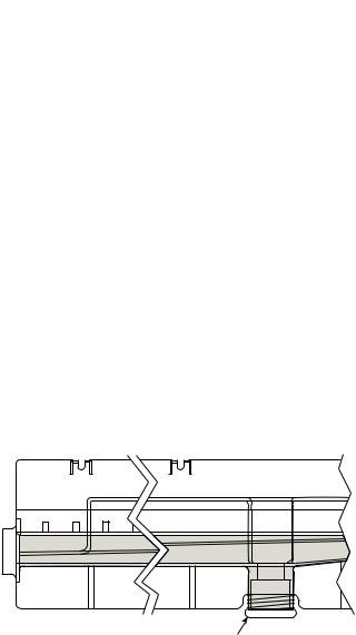
CONDENSATE PAN (SIDE VIEW)
DRAIN PLUG
NOTE: Drain plug is shown in factory-installed position.
Fig. 4 — Internal Trap Condensate Drain
POSITIONING — Maintain clearance around and above unit to provide minimum distance from combustible materials, proper airflow, and service access. See Fig. 6. A properly positioned unit will have the following clearances between unit and roof curb: 1/4-in. clearance between roof curb and base rails on each side and duct end of unit; 1/4-in. clearance between roof curb and condenser coil end of unit. (See Fig. 2, section C-C.)
Do not install unit in an indoor location. Do not locate unit air inlets within 10 ft of exhaust vents or other sources of contaminated air or as local codes require.
Be sure that unit is installed so that snow will not block the combustion intake or flue outlet.
Unit may be installed directly on wood flooring or on Class A, B, or C roof-covering material when roof curb is used.
Although unit is weatherproof, guard against water from higher level runoff and overhangs.
Flue vent discharge must have a minimum horizontal clearance of 4 ft from electric and gas meters, gas regulators, and gas relief equipment.
Minimum distance between unit and other electrically live parts is 48 inches.
Flue gas can deteriorate building materials. Orient unit such that flue gas will not affect building materials.
Adequate combustion-air space must be provided for proper operation of this equipment. Be sure that installation complies with all local codes and Section 5.3, Air for Combustion and Ventilation, NFGC (National Fuel Gas Code), and ANSI (American National Standards Institute) Z223.1, and NFPA (National Fire Protection Association) 54 TIA-54-84-1. In Canada, installation must be in accordance with the CAN1B149 installation codes for gas burning appliances.
After unit is in position, remove rigging skids and shipping materials.
Step 5 — Install Flue Hood — Flue hood is shipped screwed to the burner compartment access panel. Remove from shipping location and using screws provided, install flue hood and screen in location shown in Fig. 7.
For units size 004-006 being installed in California Air Quality Management Districts, which require NOx emissions of 40 nanograms/joule or less, a field-installed low NOx kit must be used.
Step 6 — Install Gas Piping — Unit is equipped for use with type of gas shown on nameplate. Refer to local building codes, or in the absence of local codes, to ANSI Z223.1 entitled National Fuel Gas Code. In Canada, installation must be in accordance with the CAN1.B149.1 and CAN1.B149.2 installation codes for gas burning appliances.
For natural gas applications, gas pressure at unit gas connection must not be less than 4 in. wg or greater than 13.0 in. wg while unit is operating. On 48TJ005,006,007 high heat units, the gas pressure at unit gas connection must not be less than 5 in. wg or greater than 13 in. wg while the unit is operating. For propane applications, the gas pressure must not be less than 5 in. wg or greater than 13 in. wg at the unit connection.
Size gas sully piping for 0.5 in. wg maximum pressure drop. Do not use supply pipe small than unit gas connection. Support gas piping as shown in the table in Fig. 8. For example, a 3/4-in. gas pipe must have one field-fabricated support beam every 8 ft. Therefore, an 18-ft long gas pipe would have a minimum of 2 support beams, a 48-ft long pipe would have a minimum of 6 support beams.
See Fig. 8 for typical pipe guide and locations of external manual main shutoff valve.
4
NOTES:
1. Dimension in ( ) is in millimeters.
2.Hook rigging shackles through holes in base rail, as shown in detail ‘‘A.’’ Holes in base rails are centered around the unit center of gravity. Use wooden top skid when rigging to prevent rigging straps from damaging unit.
3.Unit weights do not include economizer. See Table 1 for economizer weights.
All panels must be in place when rigging.
|
MAX |
|
DIMENSIONS |
|
|
||||
UNIT |
WEIGHT |
‘‘A’’ |
‘‘B’’ |
|
‘‘C’’ |
||||
|
lb |
kg |
in. |
mm |
in. |
mm |
|
in. |
mm |
48TJE,TJF004 |
510 |
231 |
|
|
|
|
|
|
|
48TJD,TJE,TJF005 |
520 |
236 |
73.69 |
1872 |
37.50 |
953 |
|
33.35 |
847 |
48TJD,TJE,TJF006 |
540 |
245 |
|
||||||
48TJD,TJE,TJF007 |
615 |
279 |
|
|
|
|
|
|
|
Fig. 5 — Rigging Details
Step 7 — Make Electrical Connections
Unit cabinet must have an uninterrupted, unbroken electrical ground to minimize the possibility of personal injury if an electrical fault should occur. This ground may consist of electrical wire connected to unit ground lug in control compartment, or conduit approved for electrical ground when installed in accordance with NEC (National Electrical Code), ANSI/NFPA, latest edition, and local electrical codes. Do not use gas piping as an electrical ground. Failure to follow this warning could result in the installer being liable for personal injury of others.
FIELD POWER SUPPLY — All units except 208/230-v units are factory wired for the voltage shown on the nameplate. If the 208/230-v unit is to be connected to a 208-v power supply, the transformer must be rewired by disconnecting the black wire from the 230-v terminal wire on the transformer and connecting it to the 200-v red terminal of the transformer.
Refer to unit label diagram for additional information. Wiring leads are provided for field service. Use copper conductors only when splice connectors are used.
When installing units, provide a disconnect per NEC.
All field wiring must comply with NEC and local requirements. In Canada, electrical connections must be in accordance with CSA (Canadian Standards Association) C22.1 Canadian Electrical Code Part One.
DISCONNECT BOX LOCATION — The field-supplied disconnect box may be mounted on the unit’s end panel or on the corner post. Mount disconnect box on the left side of the rating plate when mounting on the unit’s end panel. Do not mount the disconnect box over the unit rating plate. When mounting disconnect box on corner post, secure disconnect box to corner post and condenser coil top cover. See Fig. 7.
A disconnect box mounting space is available when an optional or accessory condenser coil grille is used. Mount the disconnect on the sheet metal provided with the condenser coil grille. The sheet metal is located adjacent to the corner post on the left side of the power wiring access panel.
Install field wiring as follows:
1.Connect ground lead to chassis ground connection when using separate ground ties.
2.Install conduit between disconnect and side panel. Insert conduit through power supply knockout opening. See Fig. 9.
3.Connect power lines to power wiring leads.
4.Pigtails are provided for field power connections and are located inside the burner access panel. See Fig. 10 and 11. Use factory-supplied splices or Underwriters’ Laboratories (UL) approved copper connector.
5
Table 1 — Physical Data
UNIT SIZE 48TJ |
|
E/F004 |
|
|
D/E/F005 |
|
|
D/E/F006 |
|
|
D/E/F007 |
NOMINAL CAPACITY (tons) |
|
3 |
|
|
4 |
|
|
5 |
|
|
6 |
OPERATING WEIGHT (lb) |
|
|
|
|
|
|
|
|
|
|
|
Unit |
|
|
|
|
|
|
|
|
|
|
|
Al/Al* |
|
460 |
|
|
470 |
|
|
490 |
|
|
565 |
Al/Cu* |
|
465 |
|
|
476 |
|
|
497 |
|
|
576 |
Cu/Cu* |
|
468 |
|
|
482 |
|
|
505 |
|
|
587 |
Economizer |
|
|
|
|
|
|
|
|
|
|
|
Durablade |
|
34 |
|
|
34 |
|
|
34 |
|
|
34 |
EconoMi$er |
|
47 |
|
|
47 |
|
|
47 |
|
|
47 |
Roof Curb† |
|
115 |
|
|
115 |
|
|
115 |
|
|
115 |
COMPRESSOR |
|
|
|
|
Reciprocating |
|
|
|
|
|
Scroll |
Quantity |
|
1 |
|
|
1 |
|
|
1 |
|
|
1 |
|
|
|
|||||||||
No. Cylinders (per Circuit) |
|
2 |
|
|
2 |
|
|
2 |
|
|
2 |
Oil (oz) |
|
50 |
|
|
50 |
|
|
50 |
|
|
54 |
REFRIGERANT TYPE |
|
|
|
|
|
R-22 |
|
||||
Expansion Device |
|
|
|
|
Acutrol™ Metering Device |
|
|||||
Operating Charge (lb-oz) |
|
|
|
|
|
|
|
|
|
|
|
|
|
|
|
|
|
|
|
|
|
|
|
Circuit 1 |
|
4-4 |
|
|
6-6 |
|
|
6-14 |
|
|
9-0 |
Circuit 2 |
|
— |
|
|
— |
|
|
— |
|
|
— |
CONDENSER COIL |
|
|
Enhanced Copper Tubes, Aluminum Lanced Fins |
|
|||||||
Rows...Fins/in. |
|
1...17 |
|
|
2...17 |
|
|
2...17 |
|
|
2...17 |
|
|
|
|
||||||||
Total Face Area (sq ft) |
|
8.36 |
|
|
8.36 |
|
|
10.42 |
|
|
10.42 |
CONDENSER FAN |
|
|
|
|
Propeller Type |
|
|||||
Nominal Cfm |
|
3500 |
|
|
4000 |
|
|
4000 |
|
|
4000 |
|
|
|
|
||||||||
Quantity...Diameter (in.) |
|
1...22.0 |
|
|
1...22.0 |
|
|
1...22.0 |
|
|
1...22.0 |
Motor Hp...Rpm |
|
1/4...1100 |
|
|
1/4...1100 |
|
|
1/4...1100 |
|
|
1/4...1100 |
Watts Input (Total) |
|
325 |
|
|
325 |
|
|
325 |
|
|
325 |
EVAPORATOR COIL |
|
|
Enhanced Copper Tubes, Aluminum Double-Wavy Fins |
|
|||||||
Rows...Fins/in. |
|
2...15 |
|
|
2...15 |
|
|
3...15 |
|
|
4...15 |
|
|
|
|
||||||||
Total Face Area (sq ft) |
|
4.17 |
|
|
5.5 |
|
|
5.5 |
|
|
5.5 |
EVAPORATOR FAN |
|
|
|
|
Centrifugal Type |
|
|||||
Quantity...Size (in.) |
Std |
1...10 x 10 |
|
|
1...10 x 10 |
|
|
1...11 x 10 |
|
|
1...10 x 10 |
|
|
|
|
||||||||
|
Alt |
1...10 x 10 |
|
|
1...10 x 10 |
|
|
1...10 x 10 |
|
|
— |
|
High-Static |
1...10 x 10 |
|
|
1...10 x 10 |
|
|
1...11 x 10 |
|
|
1...10 x 10 |
Type Drive |
Std |
Direct |
|
|
Direct |
|
|
Direct |
|
|
Belt |
|
Alt |
Belt |
|
|
Belt |
|
|
Belt |
|
|
— |
Nominal Cfm |
High-Static |
Belt |
|
|
Belt |
|
|
Belt |
|
|
Belt |
|
1200 |
|
|
1600 |
|
|
2000 |
|
|
2400 |
|
Maximum Continuous Bhp |
Std |
.34 |
|
|
.75 |
|
|
1.20 |
|
|
2.40 |
|
Alt |
1.00 |
|
|
1.00 |
|
|
1.30/2.40** |
|
|
— |
|
High-Static |
2.40 |
|
|
2.40 |
|
|
2.90 |
|
|
2.90 |
Motor Frame Size |
Std |
48 |
|
|
48 |
|
|
48 |
|
|
56 |
|
Alt |
48 |
|
|
48 |
|
|
56 |
|
|
— |
|
High-Static |
56 |
|
|
56 |
|
|
56 |
|
|
56 |
Nominal Rpm High/Low |
Std |
860/800 |
|
|
1075/970 |
|
|
1075/970 |
|
|
— |
|
Alt |
1620 |
|
|
1620 |
|
|
1725 |
|
|
— |
|
High-Static |
1725 |
|
|
1725 |
|
|
1725 |
|
|
1725 |
Fan Rpm Range |
Std |
— |
|
|
— |
|
|
— |
|
|
1070-1460 |
|
Alt |
760-1000 |
|
|
835-1185 |
|
|
900-1300 |
|
|
— |
Motor Bearing Type |
High-Static |
1075-1455 |
|
|
1075-1455 |
|
|
1300-1685 |
|
|
1300-1685 |
|
Ball |
|
|
Ball |
|
|
Ball |
|
|
Ball |
|
Maximum Allowable Rpm |
|
2100 |
|
|
2100 |
|
|
2100 |
|
|
2100 |
Motor Pulley Pitch Diameter Min/Max (in.) |
Std |
— |
|
|
— |
|
|
— |
|
|
2.8/3.8 |
|
Alt |
1.9/2.9 |
|
|
1.9/2.9 |
|
|
2.4/3.4 |
|
|
— |
|
High-Static |
2.8/3.8 |
|
|
2.8/3.8 |
|
|
3.4/4.4 |
|
|
3.4/4.4 |
Nominal Motor Shaft Diameter (in.) |
Std |
1/2 |
|
|
1/2 |
|
|
1/2 |
|
|
5/8 |
|
Alt |
1/2 |
|
|
1/2 |
|
|
5/8 |
|
|
— |
Fan Pulley Pitch Diameter (in.) |
High-Static |
5/8 |
|
|
5/8 |
|
|
5/8 |
|
|
5/8 |
Std |
— |
|
|
— |
|
|
— |
|
|
4.5 |
|
|
Alt |
4.5 |
|
|
4.0 |
|
|
4.5 |
|
|
— |
|
High-Static |
4.5 |
|
|
4.5 |
|
|
4.5 |
|
|
4.5 |
Belt, Quantity...Type...Length (in.) |
Std |
— |
|
|
— |
|
|
— |
|
|
1...A...40 |
|
Alt |
1...A...34 |
|
|
1...A...34 |
|
|
1...A...39 |
|
|
— |
|
High-Static |
1...A...39 |
|
|
1...A...39 |
|
|
1...A...40 |
|
|
1...A...40 |
Pulley Center Line Distance (in.) |
Std |
— |
|
|
— |
|
|
— |
|
|
14.7-15.5 |
|
Alt |
10.0-12.4 |
|
|
10.0-12.4 |
|
|
14.7-15.5 |
|
|
— |
|
High-Static |
10.0-12.4 |
|
|
10.0-12.4 |
|
|
14.7-15.5 |
|
|
14.7-15.5 |
Speed Change per Full Turn of |
Std |
— |
|
|
— |
|
|
— |
|
|
80 |
Movable Pulley Flange (rpm) |
Alt |
48 |
|
|
70 |
|
|
80 |
|
|
— |
|
High-Static |
65 |
|
|
65 |
|
|
60 |
|
|
60 |
Movable Pulley Maximum Full Turns |
Std |
— |
|
|
— |
|
|
— |
|
|
5 |
From Closed Position |
Alt |
5 |
|
|
5 |
|
|
5 |
|
|
— |
|
High-Static |
6 |
|
|
6 |
|
|
5 |
|
|
5 |
Factory Setting |
Std |
— |
|
|
— |
|
|
— |
|
|
3 |
|
Alt |
3 |
|
|
3 |
|
|
3 |
|
|
— |
Factory Speed Setting (rpm) |
High-Static |
31/2 |
|
|
31/2 |
|
|
31/2 |
|
|
31/2 |
Std |
— |
|
|
— |
|
|
— |
|
|
1225 |
|
|
Alt |
856 |
|
|
975 |
|
|
1060 |
|
|
— |
Fan Shaft Diameter at Pulley (in.) |
High-Static |
1233 |
|
|
1233 |
|
|
1396 |
|
|
1396 |
|
5/8 |
|
|
5/8 |
|
|
5/8 |
|
|
5/8 |
|
|
LEGEND |
|
Al |
— |
Aluminum |
Bhp |
— |
Brake Horsepower |
Cu |
— |
Copper |
*Evaporator coil fin material/condenser coil fin material. Contact your local representative for details about coated fins.
†Weight of 14-in. roof curb. **Single phase/three-phase.
††Rollout switch lockout is manually reset by interrupting power to unit or resetting thermostat.
NOTES:
1.The 48TJ004-007 units have a loss-of-charge (low pressure) switch located in the liquid line.
2.High-static motor not available on single-phase units.
6
Table 1 — Physical data (cont)
UNIT SIZE 48TJ |
|
E/F004 |
D/E/F005 |
D/E/F006 |
D/E/F007 |
FURNACE SECTION |
|
|
|
|
|
Rollout Switch Cutout |
|
|
|
|
|
Temp (F)†† |
|
195 |
195 |
195 |
195 |
Burner Orifice Diameter |
|
|
|
|
|
(in. ...drill size) |
|
|
|
|
|
Natural Gas |
Std |
.113...33 |
.113...33/.113...33/.129...30 |
.113...33/.113...33/.129...30 |
.113...33/.113...33/.129...30 |
Liquid Propane |
Alt |
.089...43 |
.089...43/.089...43/.102...38 |
.089...43/.089...43/.102...38 |
.089...43/.089...43/.102...38 |
Thermostat Heat Anticipator |
|
|
|
|
|
Setting (amps) |
|
|
|
|
|
208/230 v and 575 Stage 1 |
|
.14 |
.14 |
.14 |
.14 |
Stage 2 |
|
.14 |
.14 |
.14 |
.14 |
460 v Stage 1 |
|
.14 |
.14 |
.14 |
.14 |
Stage 2 |
|
.14 |
.14 |
.14 |
.14 |
Gas Input (Btuh) Stage 1 |
|
74,000/82,000 |
74,000/115,000/120,000 |
74,000/115,000/120,000 |
74,000/115,000/120,000 |
Stage 2 |
|
—/115,000 |
—/—/150,000 |
—/—/150,000 |
—/—/150,000 |
Efficiency (Steady State) (%) |
|
80 |
80 |
80 |
80 |
Temperature Rise Range |
|
25-55/55-85 |
25-55/35-65/50-80 |
25-55/35-65/50-80 |
25-55/35-65/50-80 |
Manifold Pressure (in. wg) |
|
|
|
|
|
Natural Gas |
Std |
3.5 |
3.5 |
3.5 |
3.5 |
Liquid Propane |
Alt |
3.5 |
3.5 |
3.5 |
3.5 |
Gas Valve Quantity |
|
1 |
1 |
1 |
1 |
Gas Valve Pressure Range |
|
|
|
|
|
Psig |
|
0.180-0.487 |
0.180-0.487 |
0.180-0.487 |
0.180-0.487 |
in. wg |
|
5.0-13.5 |
5.0-13.5 |
5.0-13.5 |
5.0-13.5 |
Field Gas Connection |
|
|
|
|
|
Size (in.) |
|
1/2 |
1/2 |
1/2 |
1/2 |
HIGH-PRESSURE SWITCH (psig) |
|
|
|
|
|
Standard Compressor |
|
|
450 ± 50 |
|
500 ± 50 |
Internal Relief (Differential) |
|
|
|
|
|
Cutout |
|
|
428 |
|
428 |
Reset (Auto.) |
|
|
320 |
|
320 |
LOSS-OF-CHARGE (LOW PRESSURE) |
|
|
|
|
|
SWITCH (psig) |
|
|
|
|
|
Cutout |
|
|
|
7 ± 3 |
|
Reset (Auto.) |
|
|
|
22 ± 7 |
|
FREEZE PROTECTION THERMOSTAT (F) |
|
|
|
|
|
Opens |
|
|
|
30 ± 5 |
|
Closes |
|
|
|
45 ± 5 |
|
OUTDOOR-AIR INLET SCREENS |
|
|
|
Cleanable |
|
Quantity...Size (in.) |
|
|
|
1...20 x 24 x 1 |
|
RETURN-AIR FILTERS |
|
|
|
Throwaway |
|
Quantity...Size (in.) |
|
|
|
2...16 x 25 x 2 |
|
|
|
LEGEND |
Al |
— |
Aluminum |
Bhp |
— |
Brake Horsepower |
Cu |
— |
Copper |
*Evaporator coil fin material/condenser coil fin material. Contact your local representative for details about coated fins.
†Weight of 14-in. roof curb.
**Single phase/three-phase.
††Rollout switch lockout is manually reset by interrupting power to unit or resetting thermostat.
NOTES:
1.The 48TJ004-007 units have a loss-of-charge (low-pressure) switch located in the liquid line.
2.High-static motor not available on single-phase units.
7

|
STANDARD |
DURABLADE |
ECONOMI$ER |
CORNER |
CORNER |
CORNER |
CORNER |
|||||||||
UNIT |
UNIT |
ECONOMIZER |
WEIGHT |
WEIGHT |
WEIGHT |
WEIGHT |
||||||||||
48TJ |
WEIGHT |
WEIGHT |
WEIGHT |
(A) |
(B) |
|
(C) |
|
(D) |
|||||||
|
Lb |
Kg |
Lb |
Kg |
Lb |
Kg |
Lb |
Kg |
Lb |
Kg |
Lb |
|
Kg |
Lb |
|
Kg |
E/F004 |
460 |
209 |
34 |
15.4 |
47 |
21.3 |
140 |
63.5 |
105 |
47.6 |
159 |
|
72.1 |
56 |
|
25.4 |
D/E/F005 |
470 |
213 |
34 |
15.4 |
47 |
21.3 |
142 |
64.4 |
106 |
48.1 |
162 |
|
73.5 |
60 |
|
27.2 |
D/E/F006 |
490 |
222 |
34 |
15.4 |
47 |
21.3 |
150 |
68.0 |
115 |
52.2 |
160 |
|
72.6 |
65 |
|
29.5 |
D/E/F007 |
565 |
256 |
34 |
15.4 |
47 |
21.3 |
165 |
74.8 |
136 |
61.7 |
200 |
|
90.7 |
64 |
|
29.0 |
CONNECTION SIZES
A11/16″ Dia [27] Field Power Supply Hole
B3/4″-14 NPT Condensate Drain
C1/2″-14 NPT Gas Connection
NOTES:
1. Dimensions in [ ] are in millimeters.
2. Center of gravity.
3. Direction of airflow.
4.On vertical discharge units, ductwork to be attached to accessory roof curb only. For horizontal discharge units, field-supplied flanges should be attached to horizontal discharge openings, and all ductwork should be attached to the flanges.
5.Minimum clearance (local codes or jurisdiction may prevail):
a.Between unit, flue side and combustible surfaces, 36 inches.
b.Bottom of unit to combustible surfaces (when not using curb), 1 inch. Bottom of base rail to combustible surfaces (when not using curb) 0 inches.
c.Condenser coil, for proper airflow, 36 in. one side, 12 in. the other. The side getting the greater clearance is optional.
d.Overhead, 60 in. to assure proper condenser fan operation.
e.Between units, control box side, 42 in. per NEC.
f.Between unit and ungrounded surfaces, control box side, 36 in. per NEC.
g.Between unit and block or concrete walls and other grounded surfaces, control box side, 42 in. per NEC.
h.Horizontal supply and return end, 0 inches.
6.With the exception of the clearance for the condenser coil and combustion side as stated in notes 5a, b and c, a removable fence or barricade requires no clearance.
7.Units may be installed on combustible floors made from wood or Class A, B, or C roof covering material if set on base rail.
8.The vertical center of gravity is 1′-6″ [457] up from the bottom of the base rail.
BOTTOM POWER CHART, THESE HOLES REQUIRED FOR USE WITH ACCESSORY PACKAGES — CRBTMPWR001A00, (POWER AND CONTROL) AND CRBTMPWR003A00 (POWER, CONTROL, AND GAS)
|
|
|
|
|
|
|
|
|
|
|
|
THREADED |
|
|
|
|
WIRE |
|
|
|
|
|
|
|
|
|
|
REQURED |
|
|
|
|
|||||||||||||||||||||||||||||||||||||||||||
|
|
|
|
|
|
|
|
|
|
|
CONDUIT SIZE |
|
|
|
|
|
USE |
|
|
|
|
|
|
|
HOLE SIZES (MAX.) |
|
|
|
|
||||||||||||||||||||||||||||||||||||||||||||||
|
|
|
|
|
|
|
|
|
|
|
|
|
|
|
1/2″ |
|
|
|
|
|
24 V |
|
|
|
|
|
|
|
|
|
|
7/8″ [22.2] |
|
|
|
|
|||||||||||||||||||||||||||||||||||||||
|
|
|
|
|
|
|
|
|
|
|
|
|
|
|
3/4″ |
|
|
|
|
Power |
|
|
|
|
|
|
|
|
|
|
11/8″ [28.4] |
|
|
|
|
||||||||||||||||||||||||||||||||||||||||
|
|
|
|
|
|
|
|
|
|
|
|
|
1/2″ FPT |
|
|
|
|
|
Gas |
|
|
|
|
|
|
|
|
|
|
11/4″ [31.8] |
|
|
|
|
|||||||||||||||||||||||||||||||||||||||||
|
|
|
|
|
|
|
|
|
|
|
|
|
|
|
|
|
|
|
|
|
|
|
|
|
|
|
|
|
|
|
|
|
|
|
|
|
|
|
|
|
|
|
|
|
|
|
|
|
|
|
|
|
|
|
|
|
|
|
|
|
|
|
|
|
|
|
|
|
|
|
|
|
|
|
|
|
|
|
|
|
|
|
|
|
|
|
|
|
|
|
|
|
|
|
|
|
|
|
|
|
|
|
|
|
|
|
|
|
|
|
|
|
|
|
|
|
|
|
|
|
|
|
|
|
|
|
|
|
|
|
|
|
|
|
|
|
|
|
|
|
|
|
|
|
|
|
|
|
|
|
|
|
|
|
|
|
|
|
|
|
|
|
|
|
|
|
|
|
|
|
|
|
|
|
|
|
|
|
|
|
|
|
|
|
|
|
|
|
|
|
|
|
|
|
|
|
|
|
|
|
|
|
|
|
|
|
|
|
|
|
|
|
|
|
|
|
|
|
|
|
|
|
|
|
|
|
|
|
|
|
|
|
|
|
|
|
|
|
|
|
|
|
|
|
|
|
|
|
|
|
|
|
|
|
|
|
|
|
|
|
|
|
|
|
|
|
|
|
|
|
|
|
|
|
|
|
|
|
|
|
|
|
|
|
|
|
|
|
|
|
|
|
|
|
|
|
|
|
|
|
|
|
|
|
|
|
|
|
|
|
|
|
|
|
|
|
|
|
|
|
|
|
|
|
|
|
|
|
|
|
|
|
|
|
|
|
|
|
|
|
|
|
|
|
|
|
|
|
|
|
|
|
|
|
|
|
|
|
|
|
|
|
|
|
|
|
|
|
|
|
|
|
|
|
|
|
|
|
|
|
|
|
|
|
|
|
|
|
|
|
|
|
|
|
|
|
|
|
|
|
|
|
|
|
|
|
|
|
|
|
|
|
|
|
|
|
|
|
|
|
|
|
|
|
|
|
|
|
|
|
|
|
|
|
|
|
|
|
|
|
|
|
|
|
|
|
|
|
|
|
|
|
|
|
|
|
|
|
|
|
|
|
|
|
|
|
|
|
|
|
|
|
|
|
|
|
|
|
|
|
|
|
|
|
|
|
|
|
|
|
|
|
|
|
|
|
|
|
|
|
|
|
|
|
|
|
|
|
|
|
|
|
|
|
|
|
|
|
|
|
|
|
|
|
|
|
|
|
|
|
|
|
|
|
|
|
|
|
|
|
|
|
|
|
|
|
|
|
|
|
|
|
|
|
|
|
|
|
|
|
|
|
|
|
|
|
|
|
|
|
|
|
|
|
|
|
|
|
|
|
|
|
|
|
|
|
|
|
|
|
|
|
|
|
|
|
|
|
|
|
|
|
|
|
|
|
|
|
|
|
|
|
|
|
|
|
|
|
|
|
|
|
|
|
|
|
|
|
|
|
|
|
|
|
|
|
|
|
|
|
|
|
|
|
|
|
|
|
|
|
|
|
|
|
|
|
|
|
|
|
|
|
|
|
|
|
|
|
|
|
|
|
|
|
|
|
|
|
|
|
|
|
|
|
|
|
|
|
|
|
|
|
|
|
|
|
|
|
|
|
|
|
|
|
|
|
|
|
|
|
|
|
|
|
|
|
|
|
|
|
|
|
|
|
|
|
|
|
|
|
|
|
|
|
|
|
|
|
|
|
|
|
|
|
|
|
|
|
|
|
|
|
|
|
|
|
|
|
|
|
|
|
|
|
|
|
|
|
|
|
|
|
|
|
|
|
|
|
|
|
|
|
|
|
|
|
|
|
|
|
|
|
|
|
|
|
|
|
|
|
|
|
|
|
|
|
|
|
|
|
|
|
|
|
|
|
|
|
|
|
|
|
|
|
|
|
|
|
|
|
|
|
|
|
|
|
|
|
|
|
|
|
|
|
|
|
|
|
|
|
|
|
|
|
|
|
|
|
|
|
|
|
|
|
|
|
|
|
|
|
|
|
|
|
|
|
|
|
|
|
|
|
|
|
|
|
|
|
|
|
|
|
|
|
|
|
|
|
|
|
|
|
|
|
|
|
|
|
|
|
|
|
|
|
|
|
|
|
|
|
|
|
|
|
|
|
|
|
|
|
|
|
|
|
|
|
|
|
|
|
|
|
|
|
|
|
|
|
|
|
|
|
|
|
|
|
|
|
|
|
|
|
|
|
|
|
|
|
|
|
|
|
|
|
|
|
|
|
|
|
|
|
|
|
|
|
|
|
|
|
|
|
|
|
|
|
|
|
|
|
|
|
|
|
|
|
|
|
|
|
|
|
|
|
|
|
|
|
|
|
|
|
|
|
|
|
|
|
|
|
|
|
|
|
|
|
|
|
|
|
|
|
|
|
|
|
|
|
|
|
|
|
|
|
|
|
|
|
|
|
|
|
|
|
|
|
|
|
|
|
|
|
|
|
|
|
|
|
|
|
|
|
|
|
|
|
|
|
|
|
|
|
|
|
|
|
|
|
|
|
|
|
|
|
|
|
|
|
|
|
|
|
|
|
|
|
|
|
|
|
|
|
|
|
|
|
|
|
|
|
|
|
|
|
|
|
|
|
|
|
|
|
|
|
|
|
|
|
|
|
|
|
|
|
|
|
|
|
|
|
|
|
|
|
|
|
|
|
|
|
|
|
|
|
|
|
|
|
|
|
|
|
|
|
|
|
|
|
|
|
|
|
|
|
|
|
|
|
|
|
|
|
|
|
|
|
|
|
|
|
|
|
|
|
|
|
|
|
|
|
|
|
|
|
|
|
|
|
|
|
|
|
|
|
|
|
|
|
|
|
|
|
|
|
|
|
|
|
|
|
|
|
|
|
|
|
|
|
|
|
|
|
|
|
|
|
|
|
|
|
|
|
|
|
|
|
|
|
|
|
|
|
|
|
|
|
|
|
|
|
|
|
|
|
|
|
|
|
|
|
|
|
|
|
|
|
|
|
|
|
|
|
|
|
|
|
|
|
|
|
|
|
|
|
|
|
|
|
|
|
|
|
|
|
|
|
|
|
|
|
|
|
|
|
|
|
|
|
|
|
|
|
|
|
|
|
|
|
|
|
|
|
|
|
|
|
|
|
|
|
|
|
|
|
|
|
|
|
|
|
|
|
|
|
|
|
|
|
|
|
|
|
|
|
|
|
|
|
|
|
|
|
|
|
|
|
|
|
|
|
|
|
|
|
|
|
|
|
|
|
|
|
|
|
|
|
|
|
|
|
|
|
|
|
|
|
|
|
|
|
|
|
|
|
|
|
|
|
|
|
|
|
|
|
|
|
|
|
|
|
|
|
|
|
|
|
|
|
|
|
|
|
|
|
|
|
|
|
|
|
|
|
|
|
|
|
|
|
|
|
|
|
|
|
|
|
|
|
|
|
|
|
|
|
|
|
|
|
|
|
|
|
|
|
|
|
|
|
|
|
|
|
|
|
|
|
|
|
|
|
|
|
|
|
|
|
|
|
|
|
|
|
|
|
|
|
|
|
|
|
|
|
|
|
|
|
|
|
|
|
|
|
|
|
|
|
|
|
|
|
|
|
|
|
|
|
|
|
|
|
|
|
|
|
|
|
|
|
|
|
|
|
|
|
|
|
|
|
|
|
|
|
|
|
|
|
|
|
|
|
|
|
|
|
|
|
|
|
|
|
|
|
|
|
|
|
|
|
|
|
|
|
|
|
|
|
|
|
|
|
|
|
|
|
|
|
|
|
|
|
|
|
|
|
|
|
|
|
|
|
|
|
|
|
|
|
|
|
|
|
|
|
|
|
|
|
|
|
|
|
|
|
|
|
|
|
|
|
|
|
|
|
|
|
|
|
|
|
|
|
|
|
|
|
|
|
|
|
|
|
|
|
|
|
|
|
|
|
|
|
|
|
|
|
|
|
|
|
|
|
|
|
|
|
|
|
|
|
|
|
|
|
|
|
|
|
|
|
|
|
|
|
|
|
|
|
|
|
|
|
|
|
|
|
|
|
|
|
|
|
|
|
|
|
|
|
|
|
|
|
|
|
|
|
|
|
|
|
|
|
|
|
|
|
|
|
|
|
|
|
|
|
|
|
|
|
|
|
|
|
|
|
|
|
|
|
|
|
|
|
|
|
|
|
|
|
|
|
|
|
|
|
|
|
|
|
|
|
|
|
|
|
|
|
|
|
|
|
|
|
|
|
|
|
|
|
|
|
|
|
|
|
|
|
|
|
|
|
|
|
|
|
|
|
|
|
|
|
|
|
|
|
|
|
|
|
|
|
|
|
|
|
|
|
|
|
|
|
|
|
|
|
|
|
|
|
|
|
|
|
|
|
|
|
|
|
|
|
|
|
|
|
|
|
|
|
|
|
|
|
|
|
|
|
|
|
|
|
|
|
|
|
|
|
|
|
|
|
|
|
|
|
|
|
|
|
|
|
|
|
|
|
|
|
|
|
|
|
|
|
|
|
|
|
|
|
|
|
|
|
|
|
|
|
|
|
|
|
|
|
|
|
|
|
|
|
|
|
|
|
|
|
|
|
|
|
|
|
|
|
|
|
|
|
|
|
|
|
|
|
|
|
|
|
|
|
|
|
|
|
|
|
|
|
|
|
|
|
|
|
|
|
|
|
|
|
|
|
|
|
|
|
|
|
|
|
|
|
|
|
|
|
|
|
|
|
|
|
|
|
|
|
|
|
|
|
|
|
|
|
|
|
|
|
|
|
|
|
|
|
|
|
|
|
|
|
|
|
|
|
|
|
|
|
|
|
|
|
|
|
|
|
|
|
|
|
|
|
|
|
|
|
|
|
|
|
|
|
|
|
|
|
|
|
|
|
|
|
|
|
|
|
|
|
|
|
|
|
|
|
|
|
|
|
|
|
|
|
|
|
|
|
|
|
|
|
|
|
|
|
|
|
|
|
|
|
|
|
|
|
|
|
|
|
|
|
|
|
|
|
|
|
|
|
|
|
|
|
|
|
|
|
|
|
|
|
|
|
|
|
|
|
|
|
|
|
|
|
|
|
|
|
|
|
|
|
|
|
|
|
|
|
|
|
|
|
|
|
|
|
|
|
|
|
|
|
|
|
|
|
|
|
|
|
|
|
|
|
|
|
|
|
|
|
|
|
|
|
|
|
|
|
|
|
|
|
|
|
|
|
|
|
|
|
|
|
|
|
|
|
|
|
|
|
|
|
|
|
|
|
|
|
|
|
|
|
|
|
|
|
|
|
|
|
|
|
|
|
|
|
|
|
|
|
|
|
|
|
|
|
|
|
|
|
|
|
|
|
|
|
|
|
|
|
|
|
|
|
|
|
|
|
|
|
|
|
|
|
|
|
|
|
|
|
|
|
|
|
|
|
|
|
|
|
|
|
|
|
|
|
|
|
|
|
|
|
|
|
|
|
|
|
|
|
|
|
|
|
|
|
|
|
|
|
|
|
|
|
|
|
|
|
|
|
|
|
|
|
|
|
|
|
|
|
|
|
|
|
|
|
|
|
|
|
|
|
|
|
|
|
|
|
|
|
|
|
|
|
|
|
|
|
|
|
|
|
|
|
|
|
|
|
|
|
|
|
|
|
|
|
|
|
|
|
|
|
|
|
|
|
|
|
|
|
|
|
|
|
|
|
|
|
|
|
|
|
|
|
|
|
|
|
|
|
|
|
|
|
|
|
|
|
|
|
|
|
|
|
|
|
|
|
|
|
|
|
|
|
|
|
|
|
|
|
|
|
|
|
|
|
|
|
|
|
|
|
|
|
|
|
|
|
|
|
|
|
|
|
|
|
|
|
|
|
|
|
|
|
|
|
|
|
|
|
|
|
|
|
|
|
|
|
|
|
|
|
|
|
|
|
|
|
|
|
|
|
|
|
|
|
|
|
|
|
|
|
|
|
|
|
|
|
|
|
|
|
|
|
|
|
|
|
|
|
|
|
|
|
|
|
|
|
|
|
|
|
|
|
|
|
|
|
|
|
|
|
|
|
|
|
|
|
|
|
|
|
|
|
|
|
|
|
|
|
|
|
|
|
|
|
|
|
|
|
|
|
|
|
|
|
|
|
|
|
|
|
|
|
|
|
|
|
|
|
|
|
|
|
|
|
|
|
|
|
|
|
|
|
|
|
|
|
|
|
|
|
|
|
|
|
|
|
|
|
|
|
|
|
|
|
|
|
|
|
|
|
|
|
|
|
|
|
|
|
|
|
|
|
|
|
|
|
|
|
|
|
|
|
|
|
|
|
|
|
|
|
|
|
|
|
|
|
|
|
|
|
|
|
|
|
|
|
|
|
|
|
|
|
|
|
|
|
|
|
|
|
|
|
|
|
|
|
|
|
|
|
|
|
|
|
|
|
|
|
|
|
|
|
|
|
|
|
|
|
|
|
|
|
|
|
|
|
|
|
|
|
|
|
|
|
|
|
|
|
|
|
|
|
|
|
|
|
|
|
|
|
|
|
|
|
|
|
|
|
|
|
|
|
|
|
|
|
|
|
|
|
|
|
|
|
|
|
|
|
|
|
|
|
|
|
|
|
|
|
|
|
|
|
|
|
|
|
|
|
|
|
|
|
|
|
|
|
|
|
|
|
|
|
|
|
|
|
|
|
|
|
|
|
|
|
|
|
|
|
|
|
|
|
|
|
|
|
|
|
|
|
|
|
|
|
|
|
|
|
|
|
|
|
|
|
|
|
|
|
|
|
|
|
|
|
|
|
|
|
|
|
|
|
|
|
|
|
|
|
|
|
|
|
|
|
|
|
|
|
|
|
|
|
|
|
|
|
|
|
|
|
|
|
|
|
|
|
|
|
|
|
|
|
|
|
|
|
|
|
|
|
|
|
|
|
|
|
|
|
|
|
|
|
|
|
|
|
|
|
|
|
|
|
|
|
|
|
|
|
|
|
|
|
|
|
|
|
|
|
|
|
|
|
|
|
|
|
|
|
|
|
|
|
|
|
|
|
|
|
|
|
|
|
|
|
|
|
|
|
|
|
|
|
|
|
|
|
|
|
|
|
|
|
|
|
|
|
|
|
|
|
|
|
|
|
|
|
|
|
|
|
|
|
|
|
|
|
|
|
|
|
|
|
|
|
|
|
|
|
|
|
|
|
|
|
|
|
|
|
|
|
|
|
|
|
|
|
|
|
|
|
|
|
|
|
|
|
|
|
|
|
|
|
|
|
|
|
|
|
|
|
|
|
|
|
|
|
|
|
|
|
|
|
|
|
|
|
|
|
|
|
|
|
|
|
|
|
|
|
|
|
|
|
|
|
|
|
|
|
|
|
|
|
|
|
|
|
|
|
|
|
|
|
|
|
|
|
|
|
|
|
|
|
|
|
|
|
|
|
|
|
|
|
|
|
|
|
|
|
|
|
|
|
|
|
|
|
|
|
|
|
|
|
|
|
|
|
|
|
|
|
|
|
|
|
|
|
|
|
|
|
|
|
|
|
|
|
|
|
|
|
|
|
|
|
|
|
|
|
|
|
|
|
|
|
|
|
|
|
|
|
|
|
|
|
|
|
|
|
|
|
|
|
|
|
|
|
|
|
|
|
|
|
|
|
|
|
|
|
|
|
|
|
|
|
|
|
|
|
|
|
|
|
|
|
|
|
|
|
|
|
|
|
|
|
|
|
|
|
|
|
|
|
|
|
|
|
|
|
|
|
|
|
|
|
|
|
|
|
|
|
|
|
|
|
|
|
|
|
|
|
|
|
|
|
|
|
|
|
|
|
|
|
|
|
|
|
|
|
|
|
|
|
|
|
|
|
|
|
|
|
|
|
|
|
|
|
|
|
|
|
|
|
|
|
|
|
|
|
|
|
|
|
|
|
|
|
|
|
|
|
|
|
|
|
|
|
|
|
|
|
|
|
|
|
|
|
|
|
|
|
|
|
|
|
|
|
|
|
|
|
|
|
|
|
|
|
|
|
|
|
|
|
|
|
|
|
|
|
|
|
|
|
|
|
|
|
|
|
|
|
|
|
|
|
|
|
|
|
|
|
|
|
|
|
|
|
|
|
|
|
|
|
|
|
|
|
|
|
|
|
|
|
|
|
|
|
|
|
|
|
|
|
|
|
|
|
|
|
|
|
|
|
|
|
|
|
|
|
|
|
|
|
|
|
|
|
|
|
|
|
|
|
|
|
|
|
|
|
|
|
|
|
|
|
|
|
|
|
|
|
|
|
|
|
|
|
|
|
|
|
|
|
|
|
|
|
|
|
|
|
|
|
|
|
|
|
|
|
|
|
|
|
|
|
|
|
|
|
|
|
|
|
|
|
|
|
|
|
|
|
|
|
|
|
|
|
|
|
|
|
|
|
|
|
|
|
|
|
|
|
|
|
|
|
|
|
|
|
|
|
|
|
|
|
|
|
|
|
|
|
|
|
|
|
|
|
|
|
|
|
|
|
|
|
|
|
|
|
|
|
|
|
|
|
|
|
|
|
|
|
|
|
|
|
|
|
|
|
|
|
|
|
|
|
|
|
|
|
|
|
|
|
|
|
|
|
|
|
|
|
|
|
|
|
|
|
|
|
|
|
|
|
|
|
|
|
|
|
|
|
|
|
|
|
|
|
|
|
|
|
|
|
|
|
|
|
|
|
|
|
|
|
|
|
|
|
|
|
|
|
|
|
|
|
|
|
|
|
|
|
|
|
|
|
|
|
|
|
|
|
|
|
|
|
|
|
|
|
|
|
|
|
|
|
|
|
|
|
|
|
|
|
|
|
|
|
|
|
|
|
|
|
|
|
|
|
|
|
|
|
|
|
|
|
|
|
|
|
|
|
|
|
|
|
|
|
|
|
|
|
|
|
|
|
|
|
|
|
|
|
|
|
|
|
|
|
|
|
|
|
|
|
|
|
|
|
|
|
|
|
|
|
|
|
|
|
|
|
|
|
|
|
|
|
|
|
|
|
|
|
|
|
|
|
|
|
|
|
|
|
|
|
|
|
|
|
|
|
|
|
|
|
|
|
|
|
|
|
|
|
|
|
|
|
|
|
|
|
|
|
|
|
|
|
|
|
|
|
|
|
|
|
|
|
|
|
|
|
|
|
|
|
|
|
|
|
|
|
|
|
|
|
|
|
|
|
|
|
|
|
|
|
|
|
|
|
|
|
|
|
|
|
|
|
|
|
|
|
|
|
|
|
|
|
|
|
|
|
|
|
|
|
|
|
|
|
|
|
|
|
|
|
|
|
|
|
|
|
|
|
|
|
|
|
|
|
|
|
|
|
|
|
|
|
|
|
|
|
|
|
|
|
|
|
|
|
|
|
|
|
|
|
|
|
|
|
|
|
|
|
|
|
|
|
|
|
|
|
|
|
|
|
|
|
|
|
|
|
|
|
|
|
|
|
|
|
|
|
|
|
|
|
|
|
|
|
|
|
|
|
|
|
|
|
|
|
|
|
|
|
|
|
|
|
|
|
|
|
|
|
|
|
|
|
|
|
|
|
|
|
|
|
|
|
|
|
|
|
|
|
|
|
|
|
|
|
|
|
|
|
|
|
|
|
|
|
|
|
|
|
|
|
|
|
|
|
|
|
|
|
|
|
|
|
|
|
|
|
|
|
|
|
|
|
|
|
|
|
|
|
|
|
|
|
|
|
|
|
|
|
|
|
|
|
|
|
|
|
|
|
|
|
|
|
|
|
|
|
|
|
|
|
|
|
|
|
|
|
|
|
|
|
|
|
|
|
|
|
|
|
|
|
|
|
|
|
|
|
|
|
|
|
|
|
|
|
|
|
|
|
|
|
|
|
|
|
|
|
|
|
|
|
|
|
|
|
|
|
|
|
|
|
|
|
|
|
|
|
|
|
|
|
|
|
|
|
|
|
|
|
|
|
|
|
|
|
|
|
|
|
|
|
|
|
|
|
|
|
|
|
|
|
|
|
|
|
|
|
|
|
|
|
|
|
|
|
|
|
|
|
|
|
|
|
|
|
|
|
|
|
|
|
|
|
|
|
|
|
|
|
|
|
|
|
|
|
|
|
|
|
|
|
|
|
|
|
|
|
|
|
|
|
|
|
|
|
|
|
|
|
|
|
|
|
|
|
|
|
|
|
|
|
|
|
|
|
|
|
|
|
|
|
|
|
|
|
|
|
|
|
|
|
|
|
|
|
|
|
|
|
|
|
|
|
|
|
|
|
|
|
|
|
|
|
|
|
|
|
|
|
|
|
|
|
|
|
|
|
|
|
|
|
|
|
|
|
|
|
|
|
|
|
|
|
|
|
|
|
|
|
|
|
|
|
|
|
|
|
|
|
|
|
|
|
|
|
|
|
|
|
|
|
|
|
|
|
|
|
|
|
|
|
|
|
|
|
|
|
|
|
|
|
|
|
|
|
|
|
|
|
|
|
|
|
|
|
|
|
|
|
|
|
|
|
|
|
|
|
|
|
|
|
|
|
|
|
|
|
|
|
|
|
|
|
|
|
|
|
|
|
|
|
|
|
|
|
|
|
|
|
|
|
|
|
|
|
|
|
|
|
|
|
|
|
|
|
|
|
|
|
|
|
|
|
|
|
|
|
|
|
|
|
|
|
|
|
|
|
|
|
|
|
|
|
|
|
|
|
|
|
|
|
|
|
|
|
|
|
|
|
|
|
|
|
|
|
|
|
|
|
|
|
|
|
|
|
|
|
|
|
|
|
|
|
|
|
|
|
|
|
|
|
|
|
|
|
|
|
|
|
|
|
|
|
|
|
|
|
|
|
|
|
|
|
|
|
|
|
|
|
|
|
|
|
|
|
|
|
|
|
|
|
|
|
|
|
|
|
|
|
|
|
|
|
|
|
|
|
|
|
|
|
|
|
|
|
|
|
|
|
|
|
|
|
|
|
|
|
|
|
|
|
|
|
|
|
|
|
|
|
|
|
|
|
|
|
|
|
|
|
|
|
|
|
|
|
|
|
|
|
|
|
|
|
|
|
|
|
|
|
|
|
|
|
|
|
|
|
|
|
|
|
|
|
|
|
|
|
|
|
|
|
|
|
|
|
|
|
|
|
|
|
|
|
|
|
|
|
|
|
|
|
|
|
|
|
|
|
|
|
|
|
|
|
|
|
|
|
|
|
|
|
|
|
|
|
|
|
|
|
|
|
|
|
|
|
|
|
|
|
|
|
|
|
|
|
|
|
|
|
|
|
|
|
|
|
|
|
|
|
|
|
|
|
|
|
|
|
|
|
|
|
|
|
|
|
|
|
|
|
|
|
|
|
|
|
|
|
|
|
|
|
|
|
|
|
|
|
|
|
|
|
|
|
|
|
|
|
|
|
|
|
|
|
|
|
|
|
|
|
|
|
|
|
|
|
|
|
|
|
|
|
|
|
|
|
|
|
|
|
|
|
|
|
|
|
|
|
|
|
|
|
|
|
|
|
|
|
|
|
|
|
|
|
|
|
|
|
|
|
|
|
|
|
|
|
|
|
|
|
|
|
|
|
|
|
|
|
|
|
|
|
|
|
|
|
|
|
|
|
|
|
|
|
|
|
|
|
|
|
|
|
|
|
|
|
|
|
|
|
|
|
|
|
|
|
|
|
|
|
|
|
|
|
|
|
|
|
|
|
|
|
|
|
|
|
|
|
|
|
|
|
|
|
|
|
|
|
|
|
|
|
|
|
|
|
|
|
|
|
|
|
|
|
|
|
|
|
|
|
|
|
|
|
|
|
|
|
|
|
|
|
|
|
|
|
|
|
|
|
|
|
|
|
|
|
|
|
|
|
|
|
|
|
|
|
|
|
|
|
|
|
|
|
|
|
|
|
|
|
|
|
|
|
|
|
|
|
|
|
|
|
|
|
|
|
|
|
|
|
|
|
|
|
|
|
|
|
|
|
|
|
|
|
|
|
|
|
|
|
|
|
|
|
|
|
|
|
|
|
|
|
|
|
|
|
|
|
|
|
|
|
|
|
|
|
|
|
|
|
|
|
|
|
|
|
|
|
|
|
|
|
|
|
|
|
|
|
|
|
|
|
|
|
|
|
|
|
|
|
|
|
|
|
|
|
|
|
|
|
|
|
|
|
|
|
|
|
|
|
|
|
|
|
|
|
|
|
|
|
|
|
|
|
|
|
|
|
|
|
|
|
|
|
|
|
|
|
|
|
|
|
|
|
|
|
|
|
|
|
|
|
|
|
|
|
|
|
|
|
|
|
|
|
|
|
|
|
|
|
|
|
|
|
|
|
|
|
|
|
|
|
|
|
|
|
|
|
|
|
|
|
|
|
|
|
|
|
|
|
|
|
|
|
|
|
|
|
|
|
|
|
|
|
|
|
|
|
|
|
|
|
|
|
|
|
|
|
|
|
|
|
|
|
|
|
|
|
|
|
|
|
|
|
|
|
|
|
|
|
|
|
|
|
|
|
|
|
|
|
|
|
|
|
|
|
|
|
|
|
|
|
|
|
|
|
|
|
|
|
|
|
|
|
|
|
|
|
|
|
|
|
|
|
|
|
|
|
|
|
|
|
|
|
|
|
|
|
|
|
|
|
|
|
|
|
|
|
|
|
|
|
|
|
|
|
|
|
|
|
|
|
|
|
|
|
|
|
|
|
|
|
|
|
|
|
|
|
|
|
|
|
|
|
|
|
|
|
|
|
|
|
|
|
|
|
|
|
|
|
|
|
|
|
|
|
|
|
|
|
|
|
|
|
|
|
|
|
|
|
|
|
|
|
|
|
|
|
|
|
|
|
|
|
|
|
|
|
|
|
|
|
|
|
|
|
|
|
|
|
|
|
|
|
|
|
|
|
|
|
|
|
|
|
|
|
|
|
|
|
|
|
|
|
|
|
|
|
|
|
|
|
|
|
|
|
|
|
|
|
|
|
|
|
|
|
|
|
|
|
|
|
|
|
|
|
|
|
|
|
|
|
|
|
|
|
|
|
|
|
|
|
|
|
|
|
|
|
|
|
|
|
|
|
|
|
|
|
|
|
|
|
|
|
|
|
|
|
|
|
|
|
|
|
|
|
|
|
|
|
|
|
|
|
|
|
|
|
|
Fig. 6 — Base Unit Dimensions
8
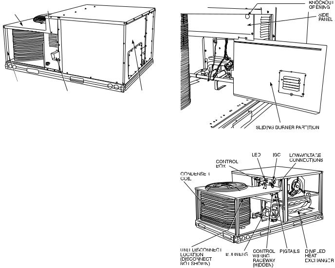
CONDENSER |
INTAKE |
COIL |
LOUVERS |
TOP COVER |
|
CORNER POST
FLUE HOOD |
END PANEL |
Fig. 7 — Flue Hood Details
LEGEND
NFGC — National Fuel Gas Code *Field supplied.
NOTE: Follow all local codes.
SPACING OF SUPPORTS
STEEL PIPE |
X |
|
NOMINAL |
||
DIMENSIONS |
||
DIAMETER |
||
(in.) |
(feet) |
|
|
||
1/2 |
6 |
|
3/4 or 1 |
8 |
|
11/4 or larger |
10 |
Fig. 8 — Gas Piping Guide (With Accessory Thru-the-Curb Service Connections)
Voltage to compressor terminals during operation must be within voltage range indicated on unit nameplate (see Table 2). On 3-phase units, voltages between phases must be balanced within 2% and the current within 10%. Use the formula shown in the legend for Table 2, Note 2 to determine the percent of voltage imbalance. Operation on improper line voltage or excessive phase imbalance constitutes abuse and may cause damage to electrical components. Such operation would invalidate any applicable Carrier warranty.
FIELD CONTROL WIRING — Install a Carrier-approved accessory thermostat assembly according to installation instructions included with the accessory. Locate thermostat assembly on a solid wall in the conditioned space to sense average temperature in accordance with thermostat installation instructions. Connect thermostat wires to terminal board.
Route thermostat cable or equivalent single leads of colored wire from subbase terminals through connector on unit to lowvoltage connections (shown in Fig. 12).
Fig. 9 — Conduit Installation
LEGEND
IGC — Integrated Gas Unit Controller
LED — Light-Emitting Diode
Fig. 10 — Component Location
NOTE: For wire runs up to 50 ft, use no. 18 AWG (American Wire Gage) insulated wire (35 C minimum). For 50 to 75 ft, use no. 16 AWG insulated wire (35 C minimum). For over 75 ft, use no. 14 AWG insulated wire (35 C minimum). All wire larger than no. 18 AWG cannot be directly connected to the thermostat and will require a junction box and splice at the thermostat.
Feed control wires through the raceway located between the condenser coil top cover and burner side panel. See Fig. 10. Connect control wires to corresponding screw terminals, the low-voltage connections located inside low-voltage access panel. See Fig. 12 for connections. The low-voltage connections provide the UL required clearance between highand low-voltage wiring.
HEAT ANTICIPATOR SETTINGS — Set heat anticipator settings at .14 amp for the first stage and .14 amp for secondstage heating, when available.
9

208/230-1-60
|
575-3-60 |
|
(SIZE 007 ONLY) |
|
LEGEND |
C |
— Contactor |
COMP |
— Compressor |
NEC |
— National Electrical Code |
TB |
— Terminal Block |
208/230-3-60 460-3-60
(SIZE 007 ONLY)
208/230-3-60 575-3-60, 460-3-60 (SIZES 004-006)
Fig. 11 — Power Wiring Connections
LEGEND
AHA — Adjustable Heat Anticipator
Field Wiring
Factory Wiring
Fig. 12 — Low-Voltage Connections
10
Table 2 — Electrical Data
UNIT |
NOMINAL |
IFM |
VOLTAGE |
COMPRESSOR |
|
OFM |
|
IFM |
COMBUSTION |
POWER |
DISCONNECT |
|||||
RANGE |
|
(ea) |
|
(ea) |
|
FAN MOTOR |
SUPPLY |
SIZE* |
||||||||
48TF |
V-Ph-Hz |
TYPE |
|
|
|
FLA |
||||||||||
Min |
Max |
RLA |
|
LRA |
Qty |
Hp |
FLA |
FLA |
MCA |
MOCP† |
FLA |
LRA |
||||
|
208/230-1-60 |
Std |
187 |
254 |
16.2 |
|
96.0 |
1 |
1/4 |
1.4 |
3.5 |
.6 |
24.5/24.5 |
30/30 |
23/23 |
106/106 |
|
Alt |
|
4.9 |
26.6/26.6 |
35/35 |
26/26 |
111/111 |
|||||||||
|
|
|
|
|
|
|
|
|
|
|
||||||
|
|
Std |
|
|
|
|
|
|
|
|
3.5 |
|
17.7/17.7 |
25/25 |
17/17 |
85/85 |
|
208/230-3-60 |
Alt |
187 |
254 |
10.2 |
|
75.0 |
1 |
1/4 |
1.4 |
4.9 |
.6 |
19.1/19.1 |
25/25 |
19/19 |
90/90 |
|
|
High |
|
|
|
|
|
|
|
|
5.2 |
|
19.4/19.4 |
25/25 |
19/19 |
109/109 |
004 |
|
Std |
|
|
|
|
|
|
|
|
1.3 |
|
7.6 |
15 |
7 |
48/48 |
|
460-3-60 |
Alt |
414 |
508 |
4.4 |
|
40.0 |
1 |
1/4 |
0.8 |
2.1 |
.3 |
8.4 |
15 |
8 |
48/48 |
|
|
High |
|
|
|
|
|
|
|
|
2.6 |
|
8.9 |
15 |
9 |
57/57 |
|
|
Std |
|
|
|
|
|
|
|
|
1.3 |
|
6.3 |
15 |
7 |
35 |
|
575-3-60 |
Alt |
518 |
632 |
3.7 |
|
31.0 |
1 |
1/4 |
0.8 |
2.1 |
.3 |
6.9 |
15 |
8 |
37 |
|
|
High |
|
|
|
|
|
|
|
|
2.6 |
|
7.3 |
15 |
7 |
45 |
|
208/230-1-60 |
Std |
187 |
254 |
23.3 |
|
118.0 |
1 |
1/4 |
1.4 |
3.5 |
.6 |
34.0/34.0 |
40/40 |
32/32 |
129/129 |
|
Alt |
|
4.9 |
35.4/35.4 |
45/45 |
34/34 |
133/133 |
|||||||||
|
|
|
|
|
|
|
|
|
|
|
||||||
|
|
Std |
|
|
|
|
|
|
|
|
3.5 |
|
24.2/24.2 |
30/30 |
23/23 |
101/101 |
|
208/230-3-60 |
Alt |
187 |
254 |
15.4 |
|
90.0 |
1 |
1/4 |
1.4 |
4.9 |
.6 |
25.6/25.6 |
30/30 |
25/25 |
105/105 |
|
|
High |
|
|
|
|
|
|
|
|
5.2 |
|
25.9/25.9 |
30/30 |
25/25 |
124/124 |
005 |
|
Std |
|
|
|
|
|
|
|
|
1.8 |
|
13.0 |
20 |
13 |
51 |
|
460-3-60 |
Alt |
414 |
508 |
8.3 |
|
45.0 |
1 |
1/4 |
0.8 |
2.1 |
.3 |
13.3 |
20 |
13 |
53 |
|
|
High |
|
|
|
|
|
|
|
|
2.6 |
|
13.8 |
20 |
13 |
62 |
|
|
Std |
|
|
|
|
|
|
|
|
1.8 |
|
10.1 |
15 |
10 |
41 |
|
575-3-60 |
Alt |
518 |
632 |
6.4 |
|
36.0 |
1 |
1/4 |
0.8 |
2.1 |
.3 |
10.3 |
15 |
11 |
42 |
|
|
High |
|
|
|
|
|
|
|
|
2.6 |
|
10.7 |
15 |
10 |
50 |
|
208/230-1-60 |
Std |
187 |
254 |
28.8 |
|
147.0 |
1 |
1/4 |
1.4 |
5.9 |
.6 |
43.3/43.3 |
60/60 |
42/42 |
161/161 |
|
Alt |
|
6.6 |
44.0/44.0 |
60/60 |
42/42 |
184/184 |
|||||||||
|
|
|
|
|
|
|
|
|
|
|
||||||
|
|
Std |
|
|
|
|
|
|
|
|
5.9 |
|
27.3/27.3 |
35/35 |
29/29 |
128/128 |
|
208/230-3-60 |
Alt |
187 |
254 |
16.3 |
|
114.0 |
1 |
1/4 |
1.4 |
5.2 |
.6 |
26.6/26.6 |
35/35 |
26/26 |
148/148 |
|
|
High |
|
|
|
|
|
|
|
|
7.5 |
|
28.9/28.9 |
35/35 |
29/29 |
174/174 |
006 |
|
Std |
|
|
|
|
|
|
|
|
3.1 |
|
13.2 |
20 |
13 |
72 |
|
460-3-60 |
Alt |
414 |
508 |
7.4 |
|
64.0 |
1 |
1/4 |
0.8 |
2.6 |
.3 |
12.7 |
15 |
12 |
81 |
|
|
High |
|
|
|
|
|
|
|
|
3.4 |
|
13.5 |
20 |
13 |
94 |
|
|
Std |
|
|
|
|
|
|
|
|
3.1 |
|
10.9 |
15 |
11 |
58 |
|
575-3-60 |
Alt |
518 |
632 |
6.2 |
|
62.0 |
1 |
1/4 |
0.8 |
3.0 |
.3 |
10.5 |
15 |
10 |
66 |
|
|
High |
|
|
|
|
|
|
|
|
3.4 |
|
12.6 |
15 |
11 |
76 |
|
208/230-3-60 |
Std |
187 |
254 |
23.6 |
|
146.0 |
1 |
1/4 |
1.4 |
5.2 |
.6 |
30.2/30.2 |
35/35 |
29/29 |
180/180 |
|
High |
|
7.5 |
32.5/32.5 |
40/40 |
32/32 |
205/205 |
|||||||||
|
|
|
|
|
|
|
|
|
|
|
||||||
007 |
460-3-60 |
Std |
414 |
508 |
10.6 |
|
73.0 |
1 |
1/4 |
0.6 |
2.6 |
.3 |
15.4 |
20 |
15 |
90 |
High |
|
3.4 |
16.1 |
20 |
16 |
103 |
||||||||||
|
|
|
|
|
|
|
|
|
|
|
||||||
|
575-3-60 |
Std |
518 |
632 |
8.5 |
|
58.4 |
1 |
1/4 |
0.6 |
2.6 |
.3 |
12.3 |
15 |
13 |
72 |
|
High |
|
3.4 |
12.9 |
20 |
14 |
82 |
|||||||||
|
|
|
|
|
|
|
|
|
|
|
||||||
|
LEGEND |
FLA |
— Full Load Amps |
HACR |
— Heating, Air Conditioning and Refrigeration |
IFM |
— Indoor (Evaporator) Fan Motor |
LRA |
— Locked Rotor Amps |
MCA |
— Minimum Circuit Amps |
MOCP — Maximum Overcurrent Protection |
|
NEC |
— National Electrical Code |
OFM |
— Outdoor (Condenser) Fan Motor |
RLA |
— Rated Load Amps |
*Used to determine minimum disconnect per NEC.
†Fuse or HACR circuit breaker.
NOTES:
1.In compliance with NEC requirements for multimotor and combination load equipment (refer to NEC Articles 430 and 440), the overcurrent protective device for the unit shall be fuse or HACR breaker. Canadian units may be fuse or circuit breaker.
2.Unbalanced 3-Phase Supply Voltage
Never operate a motor where a phase imbalance in supply voltage is greater than 2%. Use the following formula to determine the percent of voltage imbalance.
% Voltage Imbalance
= 100 x
max voltage deviation from average voltage
average voltage
Example: Supply voltage is 460-3-60.
AB = 452 v
BC = 464 v
AC = 455 v
Average Voltage =
452 + 464 + 455
3
=
1371
3
= 457
Determine maximum deviation from average voltage. (AB) 457 – 452 = 5 v
(BC) 464 – 457 = 7 v (AC) 457 – 455 = 2 v
Maximum deviation is 7 v.
Determine percent of voltage imbalance.
% Voltage Imbalance = 100 x
7
457
= 1.53%
This amount of phase imbalance is satisfactory as it is below the maximum allowable 2%.
IMPORTANT: If the supply voltage phase imbalance is more than 2%, contact your local electric utility company immediately.
11
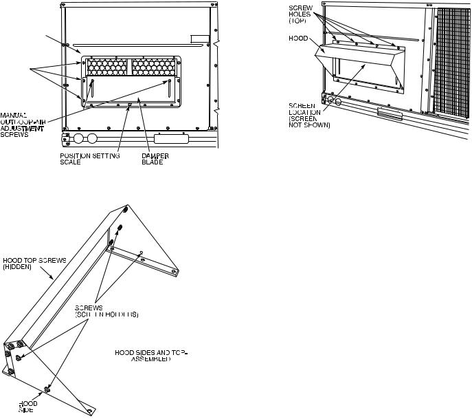
Step 8 — Make Outdoor-Air Adjustments and Install Outdoor-Air Hood
MANUAL OUTDOOR-AIR DAMPER — The outdoor-air hood and screen are attached to the basepan at the bottom of the unit for shipping.
Assembly:
1.Determine quantity of ventilation required for building. Record amount for use in Step 8.
2.Remove and save outdoor air opening panel and screws. See Fig. 13.
3.Separate hood and screen from basepan by removing the 4 screws securing them. Save all screws.
4.Replace outdoor air opening panel.
OUTDOOR
AIR OPENING
PANEL
3 SCREWS (SIDE)
Fig. 13 — Damper Panel with Manual Outdoor-Air Damper Installed
Fig. 14 — Outdoor-Air Hood Details
5.Place hood on front of outdoor air opening panel. See Fig. 14 for hood details. Secure top of hood with the 4 screws removed in Step 3. See Fig. 15.
6.Remove and save 6 screws (3 on each side) from sides of the manual outdoor-air damper.
7.Align screw holes on hood with screw holes on side of manual outdoor-air damper. See Fig. 14 and 15. Secure hood with 6 screws from Step 6.
8.Adjust minimum position setting of the damper blade by adjusting the manual outdoor-air adjustment screws on the front of the damper blade. See Fig. 13. Slide blade vertically until it is in the appropriate position determined by Fig. 16. Tighten screws.
9.Remove and save screws currently on sides of hood. Insert screen. Secure screen to hood using the screws. See Fig. 15.
Fig. 15 — Outdoor-Air Damper with
Hood Attached
Fig. 16 — Position Setting
12
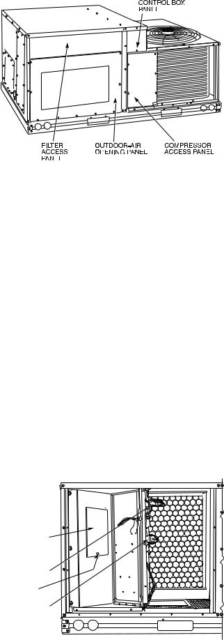
OPTIONAL DURABLADE ECONOMIZER — The optional economizer hood assembly is packaged and shipped in the filter section. Damper blades and control boards are installed at the factory and the economizer is shipped in the vertical discharge position.
NOTE: Horizontal discharge block-off plate is shipped with the air hood package. If unit is to be used for vertical discharge application, discard this plate.
NOTE: Be sure to engage Durablade economizer flange under tabs in return-air opening of the unit base.
Assembly:
1.Determine if ventilation air is required in building. If so, determine the minimum amount to be supplied by each unit and record quantity of ventilation air needed for use in Step 6.
2.Remove filter access panel by raising panel and swinging panel outward. Panel is now disengaged from track and can be removed. No tools are required to remove filter access panel. Remove outdoor-air opening panel. Save panels and screws. See Fig. 17. Remove optional economizer and outdoor-air damper hood package from filter section.
3.Assemble outdoor-air hood top and side plates as shown in Fig. 18. Install seal strips on hood top and sides. Put aside screen retainer and screws for later assembly. Do not attach hood to unit at this time.
4.To convert to horizontal discharge application:
a.Rotate economizer 90 degrees until the economizer motor faces the condenser section (see Fig. 19).
b.Remove screws and tape from damper then rotate the barometric relief damper hinge 90 degrees. Barometric relief damper should open vertically to operate properly.
c.Install horizontal discharge block-off plate over the opening on the access panel. (Block-off plate MUST be installed before installing hood assembly.) See Fig. 20. Remove 12-pin blue and yellow wire jumper plug and store.
5.Insert economizer plug into economizer harness. Remove tape from barometric relief damper. See Fig. 21. Remove shipping screw (see Fig. 19).
6.If ventilation air is not required, proceed to Step 7. If ventilation air is required, determine the minimum position setting for required airflow. See Fig. 22. Adjust minimum position setting by adjusting the screws on the position setting bracket. Slide bracket until the top screw is in the position determined by Fig. 22. Tighten screws.
7.Remove tape from outdoor-air thermostat (OAT). Fasten OAT to inside of hood using screws and speed clips provided. See Fig. 23. Make sure OAT terminals are positioned up.
8.Replace outdoor-air opening panel using screws from Step 2. Replace filter access panel. Ensure the filter access panel slides along the tracks and is securely engaged.
9.Fasten hood top and side plate assembly (Fig. 18) to outdoor-air opening panel with screws provided.
10.Place knob supplied with economizer on OAT. See Fig. 23. Set OAT for 3° F below indoor room thermostat setting. If accessory enthalpy control (EC) is used in place of OAT, see instructions shipped with EC for installation and adjustment. See Fig. 23.
11.Connect OAT per Fig. 24.
12.Slide outdoor-air inlet screens into screen track on hood side plate. While holding screen in place, fasten screen retainer to hood using screws provided.
NOTE: Refer to Fig. 25 for economizer barometric relief damper characteristics.
Fig. 17 — Typical Access Panel Locations
Fig. 18 — Outdoor-Air Hood Details
ECONOMIZER 
 CONTROL


 BOARD
BOARD 
BAROMETRIC 
RELIEF
DAMPER
ECONOMIZER
PLUG
SHIPPING
SCREW
ECONOMIZER
MOTOR
Fig. 19 — Horizontal Durablade
Economizer Installation
13
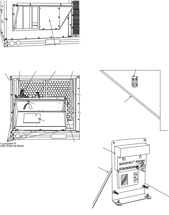
BLOCK-OFF PLATE
Fig. 20 — Horizontal Discharge Block-Off Plate
U-SHAPED |
ECONOMIZER |
|
|
|
|
OAT |
|
HOLE |
CONTROL |
ECONOMIZER |
ECONOMIZER |
TOP |
|
||
TOP |
(TERMINALS ARE UP) |
||||||
(NOT |
BOARD |
PLUG |
MOTOR |
SCREW |
|||
SHOWN) |
|
|
|
|
|
|
UNIT
WIRING |
OUTSIDE AIR |
|
SCREEN |
||
HARNESS |
||
|
 BAROMETRIC
RELIEF DAMPER
SHIPPING
SCREW
POSITION SETTING |
ENTHALPY |
BRACKET |
CONTROL |
Fig. 21 — Durablade Economizer Installed in Unit
HOOD
|
OPEN |
|
|
|
POSITIONMINIMUM |
|
|
|
|
|
|
|
|
S |
||
|
|
|
|
T |
|
3 |
|
|
1 |
|
|
|
|
|
|
|
|
P |
|
|
|
|
|
|
|
|
|
|
|
|
|
||
|
|
|
|
|
|
|
|
|
|
|
|
|
|
|
|
|
|
|
|
|
T1 |
|
4 |
|
|
2 |
|
|
5 |
|
|
|
|
|
P1 |
|
|
|
|
|
|
|
|
|
|
|
||||
|
|
|
|
|
|
|
|
|
|
|
|
|
|
|
|
|
|
|
T ID |
|
|
|
|
8 S |
CONT |
OR |
CONT |
|
|
|
|
||
|
|
|
|
|
|
% |
|
1 R |
|
|
|
|
|
|
||
|
Y |
|
|
IMUH |
|
9 U |
|
UNPOWERED W |
|
|
4 |
|
||||
|
|
|
|
|
90 |
|
|
C |
|
|
|
|
||||
|
|
30 |
60 |
70 |
|
|
8 |
T |
ACT |
|
CTS |
3 |
|
|
ENTHALPY |
|
|
60 |
|
DAMPER |
|
|
1 |
A |
5A |
TE H |
2 |
|
|
||||
|
|
|
|
|
|
m |
|
|
||||||||
|
10 |
|
|
|
|
D |
CW |
A |
2 |
RA |
|
SHO |
|
TR |
|
|
|
50 |
|
|
|
|
C |
– |
|
A |
|
|
|
|
2 |
|
|
|
|
|
|
|
|
V |
TINGS: |
|
|
|
|
|
|
|||
OUTDOOR |
55 |
|
OPEN |
|
|
|
SETPOINTS |
|
M |
ST |
IGH |
|
|
C |
|
|
|
|
|
|
|
|
|
|
|
|
AV |
|
|||||
|
|
|
|
|
|
B |
|
|
|
|
|
N |
|
|
|
|
|
|
|
|
|
|
A |
|
|
VDC |
1 |
A IN |
|
|
|
CONTROL |
|
F |
5 |
|
|
|
CLOSED DAMPER |
|
|
|
|
|
1 |
TR1 |
|
|||
|
7065 |
|
|
|
|
|
|
|
A |
RUN, |
|
|
|
|
|
|
TEMP |
|
|
|
|
|
– |
|
. |
|
ENTHALPY |
|
|
|
|
||
|
|
|
|
|
|
A |
IN |
|
|
|
|
|
||||
° |
7 |
|
|
|
|
|
|
1 |
|
|
|
|
|
|||
|
|
|
|
|
|
|
|
IN |
5A |
|
|
|
|
|
|
|
|
|
|
|
|
|
|
CCW |
|
1 |
|
|
|
|
|
|
|
|
|
|
|
|
|
|
|
|
|
3 |
|
|
|
|
|
|
|
|
|
|
|
|
|
|
|
T |
. |
|
|
|
|
|
|
. |
|
|
|
|
|
|
|
|
|
|
|
|
|
|
|
|
|
80 |
|
|
|
|
|
|
|
|
|
|
|
|
|
|
|
|
85 |
|
|
|
|
2 |
|
|
|
|
|
|
|
|
|
|
|
REV. |
|
97-367 |
|
|
|
|
|
|
|
|
|
|
|||
B
C
D S
O
RE V .
B
TR
Fig. 23 — Outdoor-Air Thermostat/
Enthalpy Control Installation
Example:
Given — Negative Pressure. . . . . . . . . . . . . . . . . . . . . . . 0.2 in. wg
Outdoor Air . . . . . . . . . .. . . . . . . . . . . . . . . . . . . . . . . . 900 cfm
Determine — Setting = 5 in.
Fig. 22 — Durablade Economizer
Minimum Position Setting
14
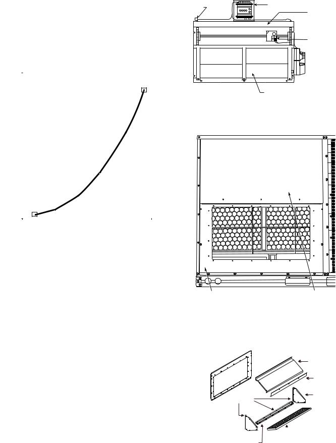
LEGEND
OAT — Outdoor-Air Thermostat
NOTE: See unit wiring diagram for details.
Fig. 24 — Wiring Connections for
Outdoor-Air Thermostat
|
0.90 |
|
|
|
|
|
|
|
|
|
|
|
|
|
|
|
|
|
|
|
|
|
|
|
|
|
|
|
|
|
|
|
|
|
|
|
|
|
|
|
|
||
|
0.80 |
|
|
|
|
|
|
|
|
|
|
|
|
|
|
|
|
|
|
|
|
wg)(in. |
0.70 |
|
|
|
|
|
|
|
|
|
|
|
|
|
|
|
|
|
|
|
|
|
|
|
|
|
|
|
|
|
|
|
|
|
|
|
|
|
|
|
|
||
0.60 |
|
|
|
|
|
|
|
|
|
|
|
|
|
|
|
|
|
|
|
|
|
DROP |
|
|
|
|
|
|
|
|
|
|
|
|
|
|
|
|
|
|
|
|
|
0.50 |
|
|
|
|
|
|
|
|
|
|
|
|
|
|
|
|
|
|
|
|
|
PRESSURE |
|
|
|
|
|
|
|
|
|
|
|
|
|
|
|
|
|
|
|
|
|
0.40 |
|
|
|
|
|
|
|
|
|
|
|
|
|
|
|
|
|
|
|
|
|
|
|
|
|
|
|
|
|
|
|
|
|
|
|
|
|
|
|
|
|
|
|
|
0.30 |
|
|
|
|
|
|
|
|
|
|
|
|
|
|
|
|
|
|
|
|
|
|
|
|
|
|
|
|
|
|
|
|
|
|
|
|
|
|
|
|
|
|
|
0.20 |
|
|
|
|
|
|
|
|
|
|
|
|
|
|
|
|
|
|
|
|
|
|
|
|
|
|
|
|
|
|
|
|
|
|
|
|
|
|
|
|
|
|
|
0.10 |
|
|
|
|
|
|
|
|
|
|
|
|
|
|
|
|
|
|
|
|
|
|
|
|
|
|
|
|
|
|
|
|
|
|
|
|
|
|
|
|
|
|
|
0.00 |
|
|
|
|
|
|
|
|
|
|
|
|
|
|
|
|
|
|
|
|
|
|
|
|
|
|
|
|
|
|
|
|
|
|
|
|
|
|
|
|
|
|
|
|
|
|
|
|
|
|
|
|
|
|
|
|
|
|
|
|
|
|
|
|
|
|
100 |
200 |
300 |
400 |
500 |
600 |
700 |
800 |
||||||||||||
|
|
|
|
|
|
|
|
|
|
|
CFM |
|
|
|
|
|
|
|
|
|
|
Fig. 25 — Durablade Economizer
Barometric Relief Damper Characteristics
OPTIONAL ECONOMI$ER — See Fig. 26 for EconoMi$er component locations.
1.To remove the existing unit filter access panel, raise the panel and swing the bottom outward. The panel is now disengaged from the track and can be removed. Remove the indoor coil access panel and discard. See Fig. 27.
If installing an optional Power Exhaust Assembly, refer to the EconoMi$er Power Exhaust Installation Instructions.
Controller should be mounted in vertical position as shown in Fig. 26.
2.Assemble the hood assembly as follows:
Remove the EconoMi$er hood from its packaging. Remove shipping brackets holding hood package to EconoMi$er. Locate the outdoor-air opening panel. See Fig. 28. Remove hood assembly shipping brackets located on the back (sloped) side of the EconoMi$er assembly. These brackets are used to retain the hood assembly during shipping only.
3.Install the 1/8 x 3/4-in. seal strip on the exhaust air hood side panels and the bottom bracket. Assemble the exhaust air hood to the outdoor-air opening panel as shown in Fig. 28, using the screws provided. Do not attach hood assembly to unit at this time.
4.Install the 1/8 x 3/4-in. seal strip on the outdoor-air hood top and side panels. Assemble the outdoor-air hood to the outdoor-air opening panel as shown in Fig. 29, using the screws provided. Do not attach hood assembly to the unit at this time.
15
ECONOMI$ER |
CONTROLLER |
|
PLUG |
||
GEAR-DRIVEN |
||
|
||
|
DAMPER |
OUTDOOR AIR |
TEMPERATURE |
SENSOR |
 ACTUATOR
BAROMETRIC RELIEF DAMPERS
Fig. 26 — EconoMi$er Component Locations
OUTDOOR-AIR |
FILTER ACCESS |
OPENING PANEL |
PANEL |
Fig. 27 — Typical Access Panel Locations
OUTDOOR AIR
OPENING PANEL 
 EXHAUST AIR HOOD TOP
SCREEN
RETAINER
|
EXHAUST AIR |
SEAL STRIP |
HOOD SIDES |
|
 EXHAUST AIR SCREEN
EXHAUST AIR BOTTOM BRACKET
Fig. 28 — Exhaust Air Hood Assembly
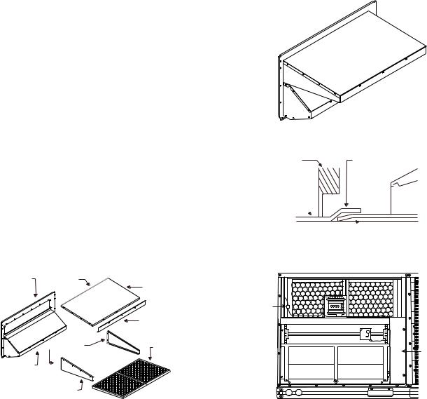
5.Slide the outdoor-air inlet screens into the screen track on the hood side panels. While holding the screens in place, fasten the screen retainer to the hood using the screws provided. Repeat the process for the barometric exhaust air screen. Do not attach completed (Fig. 30) hood assembly to unit at this time.
6.Slide the EconoMi$er assembly into the rooftop unit. See Fig. 31 and 32.
NOTE: Be sure to engage rear EconoMi$er flange under tabs in return-air opening of the unit base. See Fig. 31.
7.Install the outdoor-air block-off plate, then secure the EconoMi$er with the screws provided. See Fig. 32.
8.Remove and discard the 12-pin jumper plug from the unit wiring harness located in the upper left corner and insert the EconoMi$er plug into the unit wiring harness. Refer to wiring diagrams Fig. 33 and 34. Also refer to Fig. 35 if installing an accessory power exhaust.
9.Install the complete hood assembly on the unit and secure using the screws provided.
10.Remove the indoor fan motor access panel. See Fig. 36.
11.Mount the supply-air temperature sensor to the lower
left portion of the indoor |
blower housing with the |
||
two (2) screws provided (see Fig. 37). Connect the violet |
|||
and pink wires to the corresponding connections on the |
|||
supply-air temperature sensor. Replace the indoor fan |
|||
motor access panel. |
|
||
OUTDOOR AIR |
SEAL STRIP |
|
|
OPENING |
|
OUTDOOR AIR |
|
|
|
||
PANEL |
|
|
HOOD TOP |
|
|
|
SCREEN |
|
|
|
RETAINER |
|
|
SEAL STRIP |
OUTDOOR AIR |
|
|
INLET |
|
|
|
|
SCREENS |
ASSEMBLED |
|
|
|
EXHAUST HOOD |
|
||
|
OUTDOOR AIR |
|
|
|
HOOD SIDES |
|
|
Fig. 29 — Outdoor-Air Hood Assembly
Fig. 30 — Completed Hood Assembly
UNIT FILTER |
ECONOMI$ER CLIP |
RACK |
HVAC UNIT |
ECONOMI$ER
UNIT BASE
 ECONOMI$ER REAR
FLANGE
Fig. 31 — Rear EconoMi$er Flange Installation
WIRING |
HARNESS |
OUTDOOR
AIR
BLOCK-OFF
PLATE
Fig. 32 — EconoMi$er Installed
16
 Loading...