


OWNER'S MANUAL
Residential
Humidi®er
Part Number P110-LFP1025A, P110-WTR2019A, P110-LBP2018A, P110-SFP1016A, P110-SBP2017A
GENERAL
Congratulations on your excellent choice in this addition to your home comfort system.
Your humidi®er represents both the latest in engineering development and the culmination of many years of experience from one of the most reputable manufacturers of comfort systems.
Your new unit is among the most energy-efficient and reliable home humidi®ers available today. To assure its dependability, spend a few minutes now with this booklet. Learn about the operation of your humidi®er and the small amount of maintenance it takes to keep it operating at peak efficiency.
During the heating season, your home can become uncomfortably dry. This is because cold winter air holds very little moisture. When outdoor air is warmed to average room temperature, its relative humidity falls to even lower levels.
Proper humidity control can alleviate problems caused by excessive dryness. The additional moisture supplied by your humidi®er may enable you to reduce the temperature setting on your thermostat Ð without any loss of indoor comfort.
Your humidi®er adds water to the air inside your home. Although the rate of humidi®cation is variable, it may exceed one-half gallon of water per hour. The typical process of humidi®cation begins when water ¯ows through the humidi®er valve and soaks the large evaporator pad. Hot, dry air from the furnace passes through the pad and absorbs the water. Then, this moisture-laden air is distributed throughout the house via the ductwork. See Fig. 1. Typical humidi- ®er installations are shown in Fig. 2.
OPERATING YOUR HUMIDIFIER
Your new humidi®er is designed to operate as part of your home heating system. For performance at maximum efficiency, follow these recommendations:
·The humidi®er is controlled by a humidistat. Adjust the humidistat setting according to the outside temperature. Refer to Table 1 as a general guide. If after several days, the air in your home is too moist, lower the humidistat setting. Condensation on single-pane windows indicates excessive moisture. If the air is too dry, increase the setting.
·Continuous blower operation provides for constant humidi®cation. Continuous blower operation also minimizes temperature differences throughout the home. Furthermore, a system equipped with an electronic air cleaner offers the added bene®t of full-time air ®ltration.
·Supplyand return-air grilles should not be blocked by drapes, furniture, or other objects. Restricted air¯ow reduces the efficiency of the humidi®er, as well as that of the whole comfort system.
·The humidi®er unit must be properly maintained on a regular basis.
Table 1 Ð Humidistat Settings
OUTSIDE |
RECOMMENDED |
TEMPERATURE |
HUMIDISTAT SETTING |
(°F) |
(% RELATIVE HUMIDITY) |
−20 |
15 |
−10 |
20 (LOW) |
−0 |
25 |
10 |
30 |
20 |
35 |
30 |
40 (MED) |
|
|
EVAPORATOR
 PAD
PAD
DRY |
HUMIDIFIED |
AIR |
AIR |
DRAIN
Fig. 1 Ð Humidi®er Operation
Fig. 2 Ð Typical Humidi®er Installations
Manufacturer reserves the right to discontinue, or change at any time, speci®cations or designs without notice and without incurring obligations.
REPLACEMENT COMPONENTS DIVISION |
LITERATURE NUMBER HUM-50SO |
R CARRIER CORPORATION 1/99 |
REPLACES 2-05930 |
PRINTED IN U.S.A. |
|

Start-Up Procedures
1.Open the saddle valve on the water supply line. (See Fig. 3.) Set humidistat to the desired relative humidity. (See Fig. 4 and Table 1.)
2.Turn the furnace on and adjust the thermostat to a high temperature setting. Be sure that the furnace blower is operating.
3.Check to see if water is ¯owing into the humidi®er.
·On P110-L8P2018A or P110-LFP1025A humidi®ers, loosen the thumbscrew that holds the distributor cover to the top of the cabinet. Lift up the distributor cover slightly to make certain that water is ¯owing from the solenoid valve into the distributor pan. Do not lift the cover off the cabinet more than 1 in. when water is ¯owing. (See Fig. 5 or 6.)
·On a P110-SBP2017A humidi®er, gently pull the latch that secures the access door. Remove the door. Check to see if water is ¯owing from the solenoid valve into the evaporator pad. (See Fig. 7.)
·On a P110-SFP1016A humidi®er, open the side door or the front cover. If the front cover is opened, hold the pad assembly in place. Check to see if water is ¯owing from the solenoid valve into the distributor pan. (See Fig. 8.)
·On a P110-WTR2019A humidi®er, look through the window on front of the unit to see that the evaporator pad is rotating and water is ¯owing. (See Fig. 9.)
The P110-WTR2019A humidi®er is controlled by a float valve. Turning off the furnace will not affect the water ¯ow until ¯oat level is achieved.
4.Turn off the furnace. When the blower stops, look into the humidi®er to make sure the water is not ¯owing into the unit.
5.Replace the cover assembly and fasten securely.
6.Now, turn the furnace on and set the thermostat for desired room temperature.
Fig. 3 Ð Saddle Valve
HUMIDISTAT
Fig. 4 Ð Humidistat
SOLENOID VALVE 
DISTRIBUTOR COVER
DISTRIBUTOR PAN 
EVAPORATOR PAD
CABINET 
BOTTOM ACCESS 
PANEL
Fig. 5 Ð Humidi®er Details Ð P110-LBP2018A
SOLENOID VALVE 
DISTRIBUTOR COVER
DISTRIBUTOR PAN
EVAPORATOR PAD 
CABINET 
BOTTOM ACCESS PANEL 
Fig. 6 Ð Humidi®er Details Ð P110-LFP1025A
INLET |
SOLENOID |
|
|
CABINET |
|
||
VALVE |
DISTRIBUTOR |
||
|
|||
|
|
PAN |
|
|
|
EVAPORATOR |
|
DUCT |
|
PAD |
|
|
|
||
HOUSING |
|
|
|
|
|
SIDE |
|
|
|
ACCESS |
|
RECTIFIER |
|
DOOR |
|
|
|
DRAIN 
Fig. 7 Ð Humidi®er Details Ð P110-SBP2017A
2
CABINET
SOLENOID VALVE
FRONT COVER
DISTRIBUTOR PAN
(HIDDEN)
SCREWS (4)
PAD ASSEMBLY
SIDE ACCESS DOOR
Fig. 8 Ð Humidi®er Details Ð P110-SFP1016A
BEARING RETAINER
CABINET
PAD
PAN
Fig. 9 Ð Humidi®er Details Ð P110-WTR2019A
Shutdown Procedures Ð To shut down your humidi- ®er, close the saddle valve on the water line. Then turn off the humidistat. When set to the OFF position, the humidistat shuts off the electrical power to the solenoid valve on the humidi®er.
NOTE: If your home comfort system includes cooling, be sure the water supply to your humidi®er is turned off during the cooling season. Close the damper located in the bypass duct if one is installed. If your humidi®er is a part no. P110WTR2019A, drain and clean the water pan as described in cleaning procedures.
PERFORMING ROUTINE MAINTENANCE
With the proper maintenance and care, your humidi®er will operate economically and dependably. Maintenance can be accomplished easily by referring to the following directions. However, before performing any maintenance, consider these important safety precautions:
Disconnect all electrical power to the humidi®er and furnace before performing any service or maintenance to avoid personal injury or death.
NOTE: There may be more than one electrical disconnect switch.
Although special care has been taken to minimize sharp edges in the construction of your humidi®er, be extremely careful when handling parts or reaching into the unit to avoid personal injury.
Your humidi®er has been designed for easy disassembly to simplify cleaning and servicing. Your unit must be kept clean to maintain its efficiency.
Regular inspection allows you to determine the cleaning schedule best suited to your humidi®er's operating conditions. The frequency for required maintenance will depend most upon the available water supply. In areas where hard water and high mineral content are prevalent, more frequent cleaning and servicing may be required.
At minimum, the humidi®er will need to be cleaned at the beginning of every heating season.
Cleaning Procedures
P110-LBP2018A, P110-SBP2017A, P110-LFP1025A, AND P110-SFP1016A HUMIDIFIERS
1.Turn off all electrical power to the humidi®er and furnace or fan coil.
2.Turn off the humidi®er's water supply. (See Fig. 3.)
3.Disassemble the humidi®er.
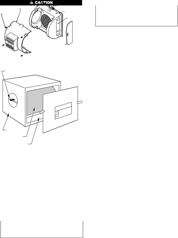
·To disassemble a P110-SBP2017A humidi®er, gently pull the latch that secures the access panel. Remove the door and slide the evaporator pad assembly out of the unit. (See Fig. 7.)
·To disassemble either a P110-LBP2018A or P110LFP1025A humidi®er, ®rst remove the water supply connection to the solenoid valve. Next, remove the screw that holds the distributor cover to the cabinet, and lift off the cover. Disconnect the drain line from the sump and loosen the thumbscrews(s) holding the sump to the cabinet. Remove the sump. Remove evaporator pad assembly. (See Fig. 5 or 6.)
·To disassemble a P110-SFP1016A humidi®er, the pad assembly can be removed from the side access door or the front cover. When removing the side door, lift the pad assembly up by holding the tabs and slide the assembly out. When removing the front cover, disconnect the quick connects to the solenoid valve, unscrew the 4 screws to the front cover, snap loose the top and bottom catches, and lay the front cover aside. Once the front cover is off, lift the pad assembly up and twist it out. The pad assembly consists of 4 parts; the distributor pan, frame, sump, and the evaporator pad. Pull the distributor pan apart from the frame and the evaporator pad can be removed. Do not force the evaporator pad in or out without removing the distributor pan as this will distort the pad. See Fig. 8.
4.Clean the humidi®er's external components.
·If your humidi®er is a P110-SBP2017A humidi®er, wash the access door and outlet drain portion of the cabinet. Make sure the drain is open.
·If your humidi®er is a P110-LBP2018A, P110-SFP- 1016A, or P110-LFP1025A unit, wash the distributor cover, sump cover, and cabinet. Be sure the inlet ports are open and clean. Then, clean the sump with a solution of detergent and water.
5.Clean the internal components of your humidi®er. Wash the distributor pan with a mild detergent and warm water. Be sure holes and slots in the pan are clean and unobstructed. Wash the evaporator pad assembly in a detergent solution. If there are scale deposits on the pad, soak
3
 Loading...