


50BV020-064
Manufacturer reserves the right to discontinue, or change at any time, specifications or designs without notice and without incurring obligations.
Catalog No. 04-53500001-01 Printed in U.S.A. Form 50BV-3SI Pg 1 10-08 Replaces: 50BV-2SI
Installation, Start-Up and
Service Instructions
CONTENTS
Page
SAFETY CONSIDERATIONS . . . . . . . . . . . . . . . . . . . . .1,2
GENERAL . . . . . . . . . . . . . . . . . . . . . . . . . . . . . . . . . . . . . . . . 2
MAJOR SYSTEM COMPONENTS . . . . . . . . . . . . . . . . . 2
Constant Volume (CV) Units. . . . . . . . . . . . . . . . . . . . . . 2
Variable Air Volume (VAV) Units . . . . . . . . . . . . . . . . . . 2
INSTALLATION . . . . . . . . . . . . . . . . . . . . . . . . . . . . . . . . 3-30
Step 1 — Complete Pre-Installation Checks . . . . . . 3
• EXAMINE THE UNIT
• UNIT STORAGE
• MODULAR UNITS
Step 2 — Rig and Place Unit . . . . . . . . . . . . . . . . . . . . . 3
• REMOVE PACKAGING
• UNIT LOCATION
• UNIT PLACEMENT
• ACOUSTICAL CONSIDERATIONS
• ASSEMBLING MODULAR UNITS
Step 3 — Install Ductwork. . . . . . . . . . . . . . . . . . . . . . . 19
• DUCT STATIC PRESSURE PROBE AND TUBING
( VAV O nl y)
• DUCT HIGH-STATIC (DHS) LIMIT SWITCH (VAV Only)
Step 4 — Make Piping Connections . . . . . . . . . . . . . 21
• CONDENSER WATER PIPING (Water-Cooled Only)
• EVAPORATOR CONDENSATE DRAIN
• HOT WATER HEATING COIL (Optional)
• WATER ECONOMIZER (Optional)
• REMOTE REFRIGERANT PIPING
(Remote Air-Cooled Only)
Step 5 — Complete Electrical Connections. . . . . . 24
• POWER WIRING
• CONTROL WIRING (CV Only)
• REMOTE CONDENSER FAN CONTACTOR WIRING
• CONTROL WIRING (VAV Only)
• SUPPLY AIR TEMPERATURE SENSOR (SAT)
• SMOKE DETECTOR/FIRE ALARM SHUTDOWN (FSD)
• ALARM (ALARM) AND WARNING (WARN) OUTPUTS
• REMOTE OCCUPANCY (ROCC)
• RETURN AIR TEMPERATURE SENSOR (RAS)
START-UP . . . . . . . . . . . . . . . . . . . . . . . . . . . . . . . . . . . . 30-48
General . . . . . . . . . . . . . . . . . . . . . . . . . . . . . . . . . . . . . . . . . 30
• CRANKCASE HEATERS
• CONFIRM THE INPUT POWER PHASE SEQUENCE
• INTERNAL WIRING
• RETURN-AIR FILTERS
• COMPRESSOR MOUNTING
• REFRIGERANT SERVICE PORTS
CV Unit Start-Up . . . . . . . . . . . . . . . . . . . . . . . . . . . . . . . . 31
• EVAPORATOR FAN
•COOLING
• HEATING (Heat Pump Units Only)
VAV Unit Start-Up . . . . . . . . . . . . . . . . . . . . . . . . . . . . . . . 42
• PERFORM AUTOMATIC RUN TEST
•CHECK VFD
• POWER UP LID DISPLAY
Page
• LOG ON TO THE LID DISPLAY
• CHANGE THE DEFAULT PASSWORD
• SET THE CLOCK
• CONFIGURE SCHEDULES
• PROGRAM SET POINTS
• CHECK SYSTEM PARAMETERS
• DISPLAY ALARM HISTORY
• CONFIGURE THE CUSTOM PROGRAMMING
SELECTIONS
• SET CONTROLLER ADDRESS
• LOG OFF FROM THE CONTROLLER
Sequence of Operation (CV Only) . . . . . . . . . . . . . . . 47
• WATER ECONOMIZER COOLING
Sequence of Operation (VAV Only) . . . . . . . . . . . . . . 48
• SUPPLY FAN
• COMPRESSOR COOLING
• WATER ECONOMIZER COOLING
• COOLING RESET
Diagnostic Features (CV Only) . . . . . . . . . . . . . . . . . . 48
VAV Control and VFD Diagnostics. . . . . . . . . . . . . . . 48
SERVICE . . . . . . . . . . . . . . . . . . . . . . . . . . . . . . . . . . . . . . . . 49
Compressor Rotation . . . . . . . . . . . . . . . . . . . . . . . . . . . 49
Fan Motor Replacement. . . . . . . . . . . . . . . . . . . . . . . . . 49
MAINTENANCE . . . . . . . . . . . . . . . . . . . . . . . . . . . . . . 49-51
Cleaning Unit Exterior. . . . . . . . . . . . . . . . . . . . . . . . . . . 49
Coil Cleaning. . . . . . . . . . . . . . . . . . . . . . . . . . . . . . . . . . . . 49
Inspection. . . . . . . . . . . . . . . . . . . . . . . . . . . . . . . . . . . . . . . 49
Air Filters . . . . . . . . . . . . . . . . . . . . . . . . . . . . . . . . . . . . . . . 49
Condensate Drains. . . . . . . . . . . . . . . . . . . . . . . . . . . . . . 49
Water-Cooled Condensers . . . . . . . . . . . . . . . . . . . . . . 49
• GRAVITY FLOW METHOD
• FORCED CIRCULATION METHOD
Fan Motor Lubrication. . . . . . . . . . . . . . . . . . . . . . . . . . . 50
Fan Bearing Lubrication . . . . . . . . . . . . . . . . . . . . . . . . 50
Fan Sheaves . . . . . . . . . . . . . . . . . . . . . . . . . . . . . . . . . . . . 50
•ALIGNMENT
Evaporator Fan Performance Adjustment . . . . . . . 51
• BELT TENSION ADJUSTMENT
Charging the System. . . . . . . . . . . . . . . . . . . . . . . . . . . . 51
• REMOTE AIR-COOLED UNITS
Compressor Oil . . . . . . . . . . . . . . . . . . . . . . . . . . . . . . . . . 51
TROUBLESHOOTING . . . . . . . . . . . . . . . . . . . . . . . . 51-65
Forcing and Clearing an Input or Output
(VAV only) . . . . . . . . . . . . . . . . . . . . . . . . . . . . . . . . . . . . 54
START-UP CHECKLIST . . . . . . . . . . . . . . . . . . .CL-1, CL-2
SAFETY CONSIDERATIONS
Installing, starting up, and servicing air-conditioning
components and equipment can be dangerous. Only trained,
qualified installers and service mechanics should install, start-
up, and service this equipment.
When working on the equipment, observe precautions in
the literature and on tags, stickers, and labels attached to the
OMNIZONE™
50BV020-064
Water-Cooled and Remote Air-Cooled
Indoor Self-Contained Systems and
Water-Cooled Heat Pumps
2
equipment. Follow all safety codes. Wear safety glasses and
work gloves.
GENERAL
Omnizone™ 50BV indoor packaged units are very flexible
for a variety of applications. These self-contained units are
available as water-cooled or remote air-cooled air conditioning
units. The 50BV units are available with either constant vol-
ume (CV) or variable air volume (VAV) controls. In addition,
the 50BV unit is available as a water-cooled heat pump. Final-
ly, Omnizone 50BV units are available in two cabinet styles.
Nominal 18 through 30-ton units are constructed in a single-
piece, unpainted galvanized cabinet. Nominal 30 through
60-ton units are available as modular units, and can be taken
apart for easier installation. Modular units are built using an un-
painted, galvanized steel cabinet with steel framework, and can
be easily disassembled without breaking the refrigerant lines.
See Table 1 for a model number reference by application.
Each unit contains multiple scroll compressors piped in
separate refrigerant circuits. Each water-cooled circuit includes
a coaxial (tube-in-tube) condenser, TXV (thermostatic expan-
sion valve), individual evaporator coils, and all interconnecting
piping. Water-cooled units are shipped fully charged with
refrigerant. Remote air-cooled units are shipped with a nitrogen
holding charge.
Each unit is equipped with one or two forward-curved cen-
trifugal blowers, to ensure quiet air delivery to the conditioned
space. Constant volume units operate at a single, adjustable fan
speed and provide zone temperature control using a standard
commercial thermostat. For VAV applications, the unit is sup-
plied with a variable frequency drive(s) (VFD) that automati-
cally adjusts blower speed to maintain a constant, adjustable
duct static pressure. Compressors are automatically staged to
provide supply air temperature control (VAV applications) or
zone temperature control using a two-stage commercial ther-
mostat (CV applications).
The 50BV units have removable access panels for easy
servicing. These panels allow access to controls, compressors,
condensers, VFD(s) (if applicable), evaporator motors, blow-
ers, belts, pulleys, and refrigeration components.
MAJOR SYSTEM COMPONENTS
Constant Volume (CV) Units
MAIN CONTROL BOARD (MCB) — The main control
board for the 50BVC, E, Q, T, U, and V units provides both
controls and diagnostics including:
• Condensate Overflow Protection
prevents unit operation in
the event that the drain pan clogs (optional sensors
required).
• Random Start
provides a programmable start with a range
of 30 to 60 seconds.
• Anti-short Cycle Timer
provides a 5-minute delay to pre-
vent compressor short cycling.
• Low Pressure Bypass Timer
bypasses the low-pressure
switch for 90 seconds to avoid nuisance trips during cold
start-up.
• High Pressure Switch Delay
is a one-second delay that pre-
vents nuisance trips at start-up.
• Brownout/Surge/Power Interruption Protection
is a
20-second moving scale that works in conjunction with the
random start timer to delay unit start when a nuisance lock-
out would otherwise have occurred. This allows the water
pumps to restart and establish water flow.
• Alarm Output
contacts provide remote fault indication.
• Test/Service Pin is a jumper that reduces all time delay
settings to 6 seconds during troubleshooting or operation
verification.
• Reset
occurs after a 5-minute delay when a fault condition
occurs. When the timer expires, the unit will restart. If the
same condition occurs a second time, the unit will be locked
out.
• Lockout Reset
requires that the unit power be cycled at the
unit controller via either the thermostat or unit disconnect.
NOTE: The refrigerant circuits on dual compressor models
are completely independent. If either stage has a fault condi-
tion the remaining stage will continue to operate without
interruption. A freeze (optional sensor required) or condensate
overflow lockout will shut down both refrigerant circuits.
• LEDs
are provided for diagnostic purposes.
Variable Air Volume (VAV) Units — The 50BVJ, K,
W, and X units come equipped with a Carrier 6400 Comfort
Controller and a VFD. Refer to the 50BV,XJ Controls, Opera-
tion and Troubleshooting manual for details.
NOTE: The VAV units utilize face split coils and should not
be operated below 50% of nominal airflow to prevent coil
freezing.
Table 1 — Model Number Reference By Application Type
LEGEND
*All units are cooling only unless specified.
WARNING
Before performing service or maintenance operations on
unit, turn off main power switch to unit and open all dis-
connects. More than one disconnect switch may be
required to deenergize this equipment. Electric shock haz-
ard can cause injury or death.
CAUTION
Use care in handling, rigging, and setting bulky equipment.
MODEL TYPE* AVAILABLE CAPACITY CONSTRUCTION CONTROLS
50BVC Water-Cooled 18 to 30 nominal tons Single-piece CV
50BVE Remote Air-Cooled 18 to 30 nominal tons Single-piece CV
50BVQ Water-Cooled Heat Pump 18 to 30 nominal tons Single-piece CV
50BVJ Water-Cooled 18 to 30 nominal tons Single-piece VAV
50BVK Remote Air-Cooled 18 to 30 nominal tons Single-piece VAV
50BVT Water-Cooled 30 to 60 nominal tons Modular CV
50BVU Remote Air-Cooled 30 to 60 nominal tons Modular CV
50BVV Water-Cooled Heat Pump 30 to 60 nominal tons Modular CV
50BVW Water-Cooled 30 to 60 nominal tons Modular VAV
50BVX Remote Air-Cooled 30 to 60 nominal tons Modular VAV
CV — Constant Volume
VAV — Variable Air Volume
3
INSTALLATION
Omnizone™ 50BV units are intended for indoor installa-
tion only. Determine building alterations required to run piping,
wiring, and ductwork. Read all installation instructions before
installing the unit.
Step 1 — Complete Pre-Installation Checks
EXAMINE THE UNIT — Examine the unit for shipping
damage. File a claim with the transit company if damage is
found. Check the shipment for completeness. Verify that the
nameplate electrical requirements match the available power
supply.
UNIT STORAGE — The 50BV units are designed and pack-
aged for indoor storage and use only. If the equipment is not
needed for immediate installation upon its arrival at the job site,
it should be left in its shipping carton and stored in a clean, dry
area. Units must only be stored or moved in the normal upright
position, as indicated by the “UP” arrows on each carton, at all
times. DO NOT STACK UNITS.
MODULAR UNITS — The 50BVT,U,V,W,X units are shipped
in multiple sections for easy movement and installation. The
separate modules will pass through a standard 36-in. steel-
framed door or service elevator. Circuit integrity is maintained
because none of the refrigerant piping requires disconnection.
Water piping connections are made with the use of heavy-duty
bronze-bodied unions so no field welding or brazing is required.
See Table 2 for the number of sections per unit.
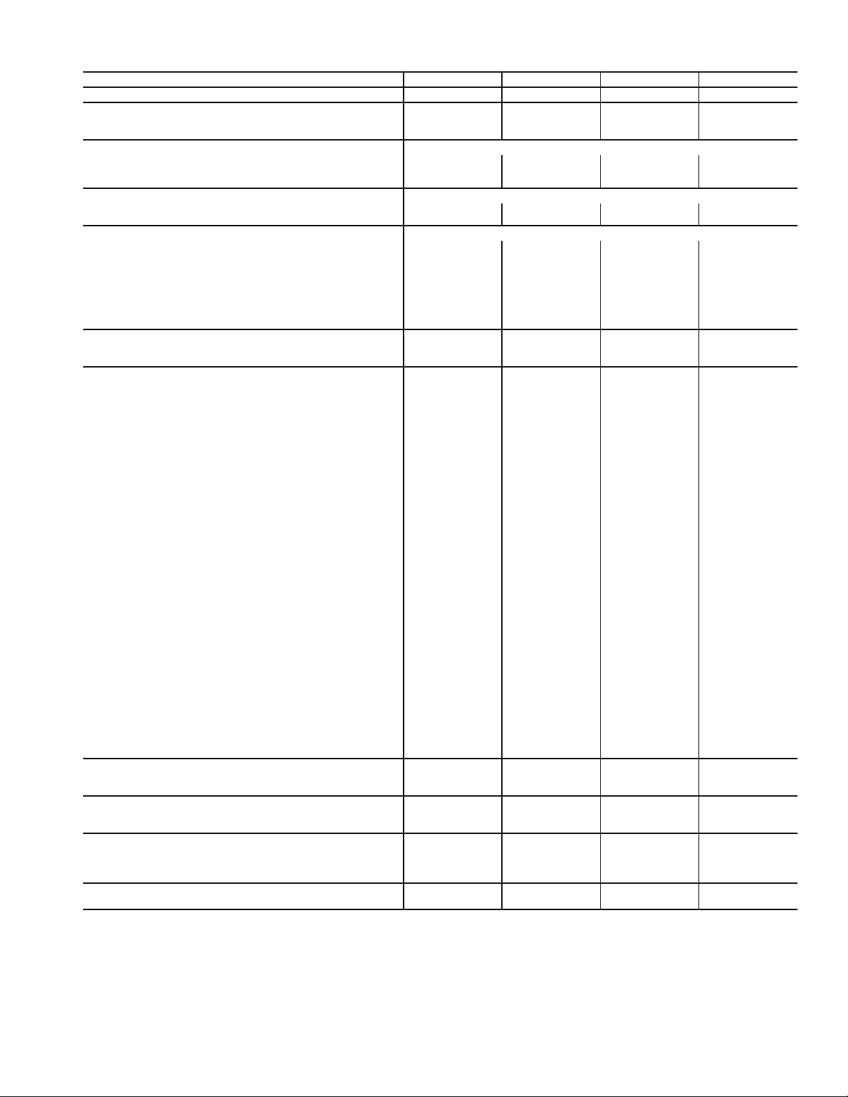
Table 2 — Modular Unit Shipping Table
NOTE: Units ship with the main air conditioning, economizer/
filter, and, when selected, the reheat coil sections assembled
together. These can be easily disassembled, as required, in the
field. The fan section(s) always ships separately.
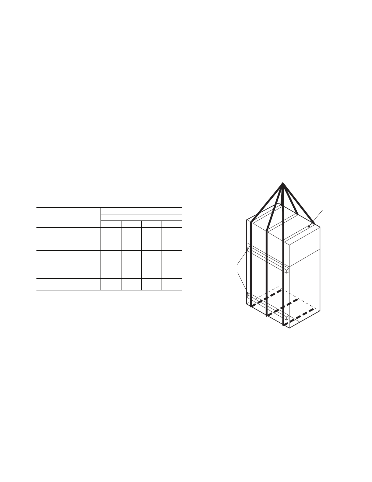
Step 2 — Rig and Place Unit — Use proper lifting
and handling practices to avoid damage to the unit. Move
modular units with a fork truck using the baserails provided, or
use spreader bars and lifting straps as shown in Fig. 1.
For single piece units, use spreader bars and rigging straps if
lifting with a crane to avoid damage to the unit. Otherwise,
move with a fork truck using the shipping pallet.
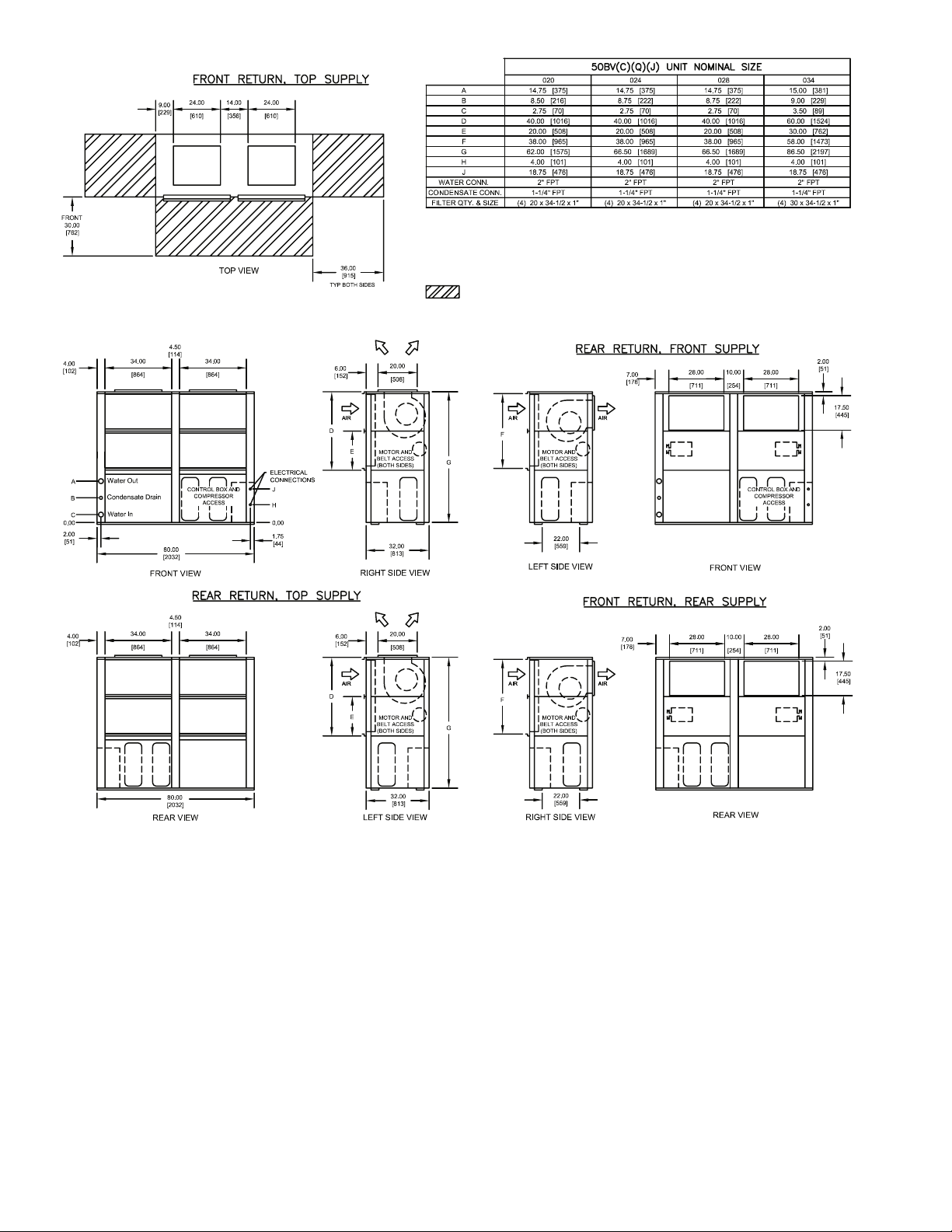
Refer to Fig. 2-14 for unit dimensions.
Refer to Tables 3A and 3B for physical data.
REMOVE PACKAGING — Remove all protective plastic,
remove and discard unit top cover protector, filter cover,
controller display protector, and water piping connection
packaging.
UNIT LOCATION — Locate the unit in an indoor area
that allows easy removal of the filters, access panels, and
accessories. Make certain enough space is available for service
personnel to perform maintenance or repairs. Provide sufficient
room to make all water, duct, and electrical connections. If the
unit is located in a small mechanical equipment room, make
sure adequate space is available for air to return freely to the
unit. These units are not approved for outdoor installations and
must be installed inside the structure. Do not locate in areas
that are subject to freezing.
UNIT PLACEMENT — Ensure that the floor is structurally
strong enough to support the weight of the equipment with
minimum deflection. A good, level floor is required for proper
unit operation and to ensure proper fit-up and alignment of all
bolt together and union coupled modules on modular units.
SECTIONS
NUMBER OF SECTIONS
50BVT, U, V, W, X
034 044 054 064
Main Air Conditioning
Weight (lb) (each)
1
2100
2
1825
2
2200
2
2225
Reheat Coil Option
Weight (lb) (each)
1
40
2
40
2
40
2
40
Economizer/Filter
Filter Section Weight (lb)
Economizer Weight (lb)
1
310
200
2
310
200
2
310
200
2
310
200
Fan Section
Weight (lb) (each)
1
650
2
650
2
650
2
650
Tot al U ni t
Weight (lb)
4
3300
8
5400
8
6150
8
6150
USE
SPREADER
BAR TO
PREVENT
DAMAGE
TO UNIT
4 X 4 ABOVE
AND BELOW
RETURN DUCT
CONNECTIONS
Fig. 1 — Modular Unit Rigging
a50-7257ef
4
STANDARD
BLOWER
ORIENTATION
OPTIONAL
BLOWER
ORIENTATION
STANDARD
BLOWER
ORIENTATION
OPTIONAL
BLOWER
ORIENTATION
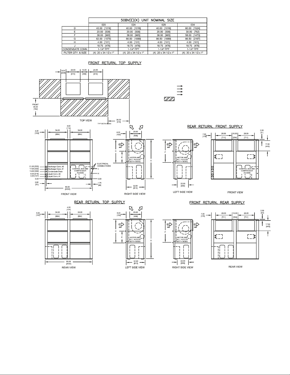
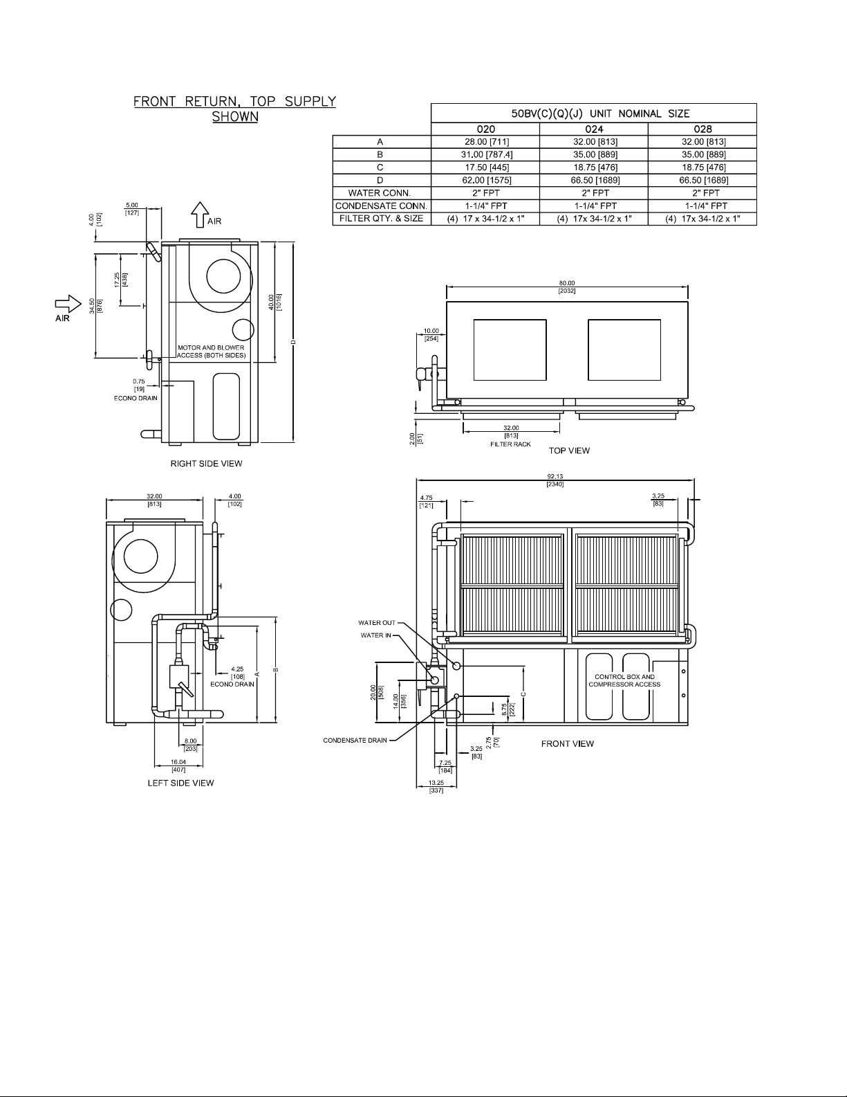
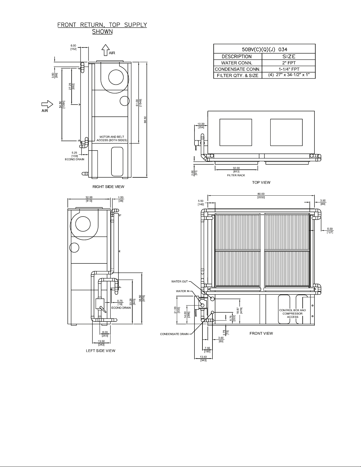
Fig. 2 — 50BVC,J,Q020-034 Dimensions
NOTES:
1. Dimensions in inches [mm].
2. VAV models (50BVJ) are rear return, top supply only.
3. Compressor, controls, and condenser access are through front panels.
4. Field power connections are 1-3/4 inches. Control connections are 7/8 inches.
5. Optional blower orientation is selected in model number nomenclature as option 9 in FIOP section
(digits 15 and 16).
Shows recommended minimum service clearances.
a50-8199
5
STANDARD
BLOWER
ORIENTATION
OPTIONAL
BLOWER
ORIENTATION
STANDARD
BLOWER
ORIENTATION
OPTIONAL
BLOWER
ORIENTATION
Fig. 3 — 50BVE,K020-034 Dimensions
NOTES:
1. Dimensions in inches [mm].
2. VAV models (50BVK) are rear return, top supply only.
3. Compressor, controls, and condenser access are through front panels.
4. Field power connections are 1-3/4 inches. Control connections are 7/8 inches.
5. Discharge (hot gas) connections are 1-1/8 in. OD.
6. Liquid line connections are 7/8 in. OD.
7. Optional blower orientation is selected in model number nomenclature as
option 9 in FIOP section (digits 15 and 16).
RECOMMENDED CONDENSER MATCHES:
50BV020 one (1) 09DK020 (50/50 split each)
50BV024 one (1) 09DK024 (50/50 split each)
50BV028 one (1) 09DK028 (50/50 split each)
50BV034 one (1) 09DK034 (50/50 split each)
Shows recommended minimum service clearances.
a50-8200
6
REAR VIEW
RETURN AIR VIEW
LEFT SIDE VIEW
80.00
FRONT VIEW
54.38
8.75
15.00
13.00
31.00
BLOWER
SECTION
ACCESS
EVAPORATOR
ACCESS
2.88
2.00
EVAPORATOR
ACCESS
BLOWER
SECTION
ACCESS
LEFT SIDE VIEW
FILTER ACCESS
ECONO COIL (Optional)
DIRECT EXPANSION
EVAPORATOR
REHEAT COIL (Optional)
STANDARD
DISCHARGE
REAR DISCHARGE
(Optional)
WATER IN
(ECONO COIL
OPTIONAL)
ELECTRICAL
81.50
BLOWER
SECTION
ACCESS
COMPRESSOR
ACCESS
COMPRESSOR
ACCESS
EVAPORATOR
ACCESS
EVAPORATOR
ACCESS
ELECTRICAL BOX
ACCESS
ELECTRICAL BOX
23.75
18.75
49.75
21.75
9.88
111.00
3.19
5.50
65.50
54.75
2.00
23.25
5.00
51.63
1.50
1.50
LIFTING SUPPORT RAIL
69.50
SHIPPING SECTION
10.75
3.75
B
A
C
D
a50-8201
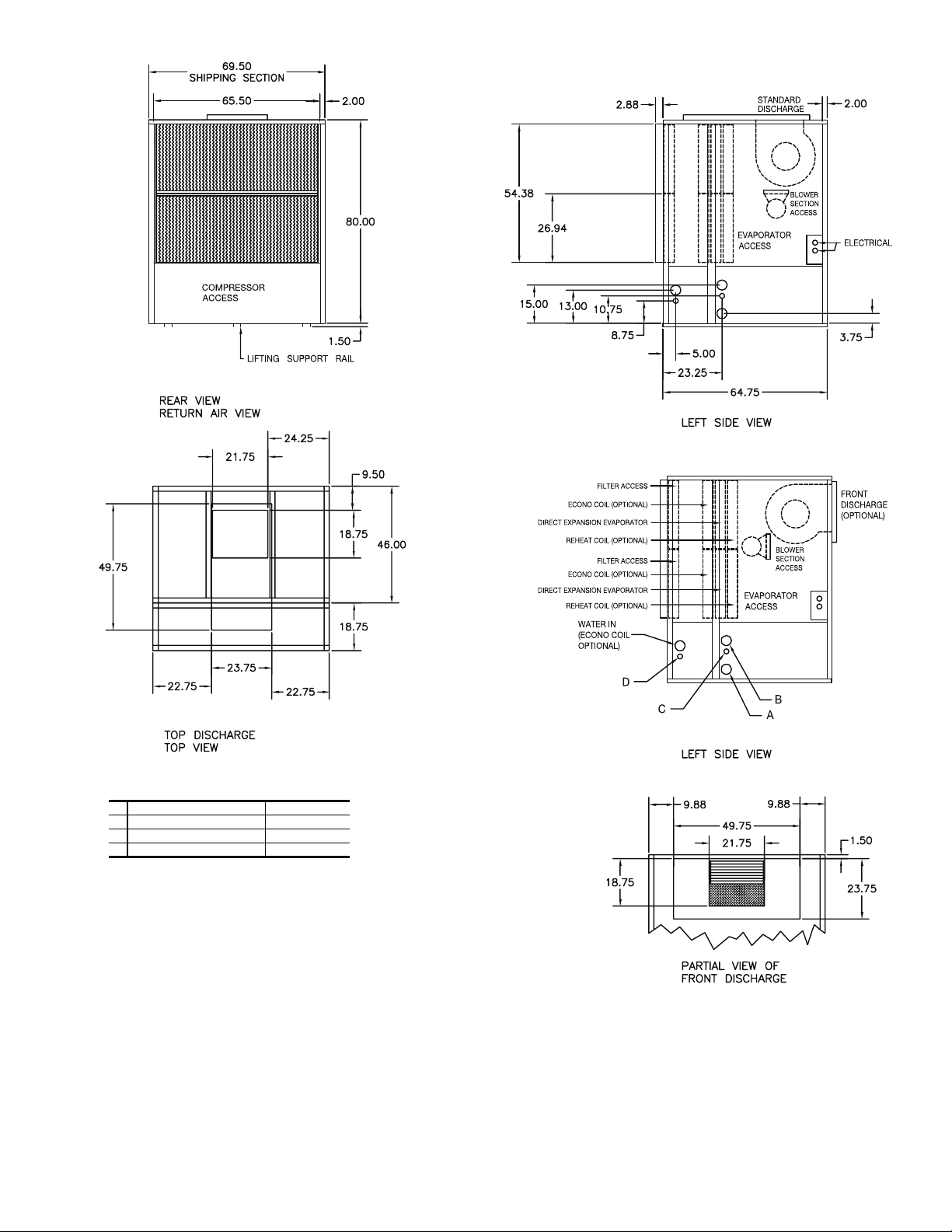
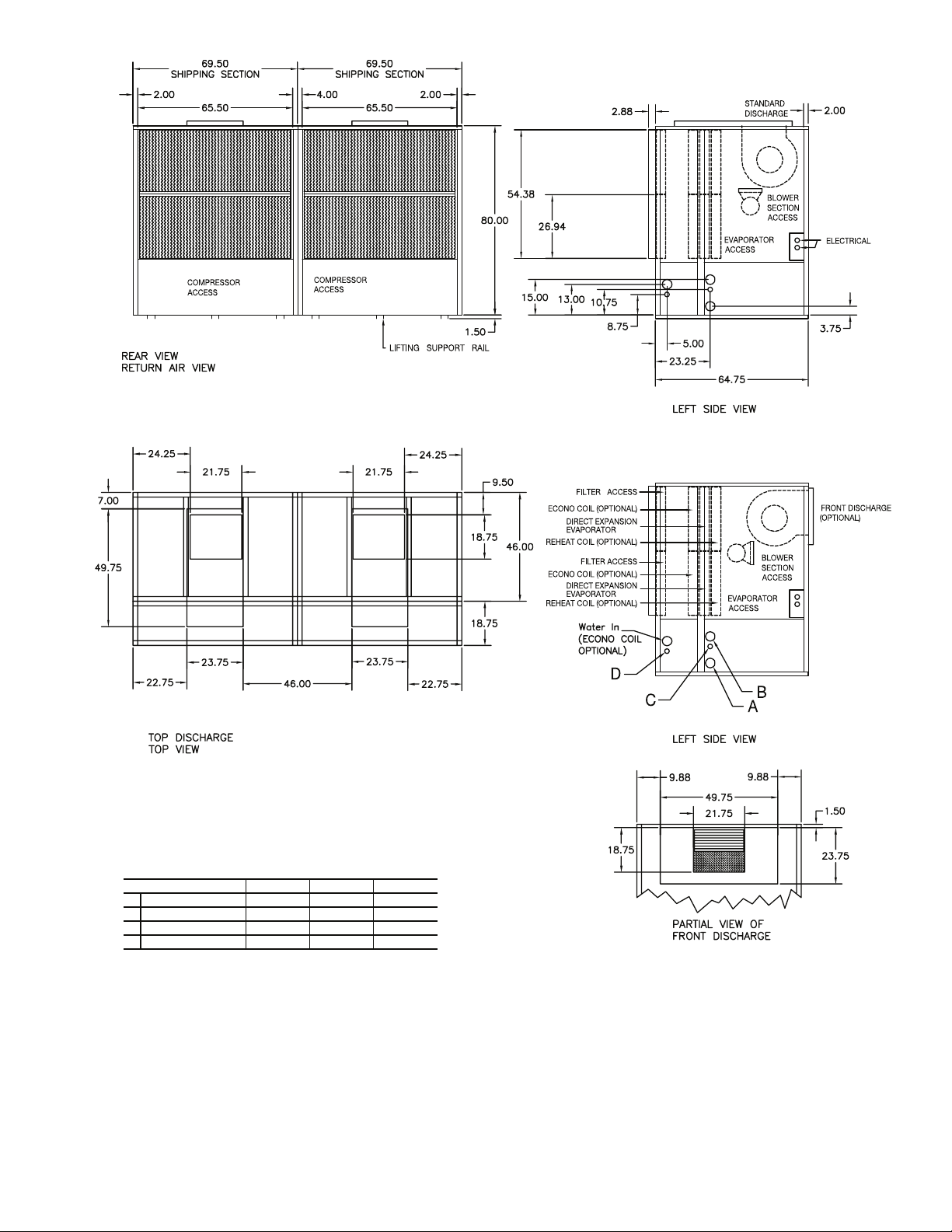
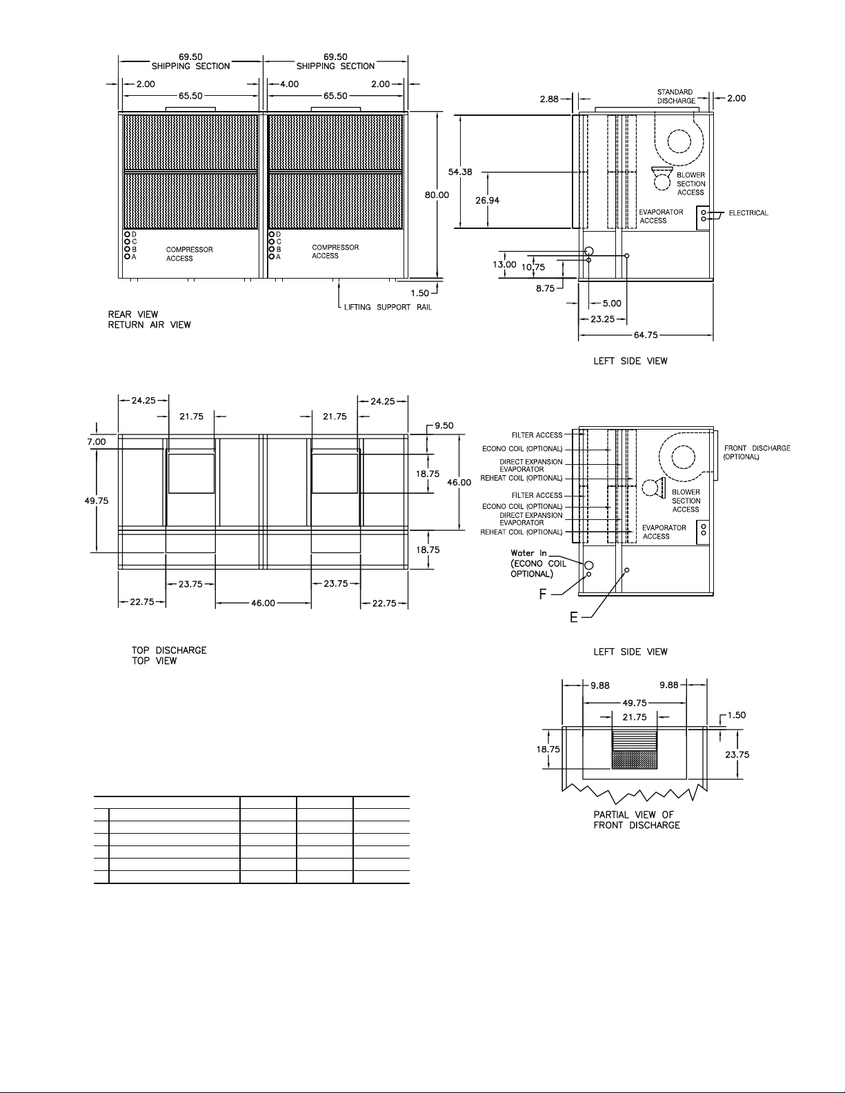
NOTES:
1. Dimensions in inches.
2. All units are rear return airflow configuration.
3. Constant volume units are available with front or rear air supply.
4. VAV units (50BVW) are available with rear supply only.
5. Recommended minimum service clearances are as follows:
a. Front and rear — 30 in. (762 mm)
b. Left or right side — 65 in. (1651 mm) for coil removal
c. Side opposite coil removal — 20 in. (508 mm)
CONNECTIONS
REPLACEMENT FILTERS : EIGHT (8) AT 17 x 27 x 4 INCHES.
A WATER OUT 2-1/2 in. FPT
B WATER IN 2-1/2 in. FPT
C CONDENSATE DRAIN 1-1/4 in. FPT
D ECONOMIZER DRAIN 1-1/4 in. FPT
Fig. 4 — 50BVT,V,W034 (High-Boy) Dimensions
7
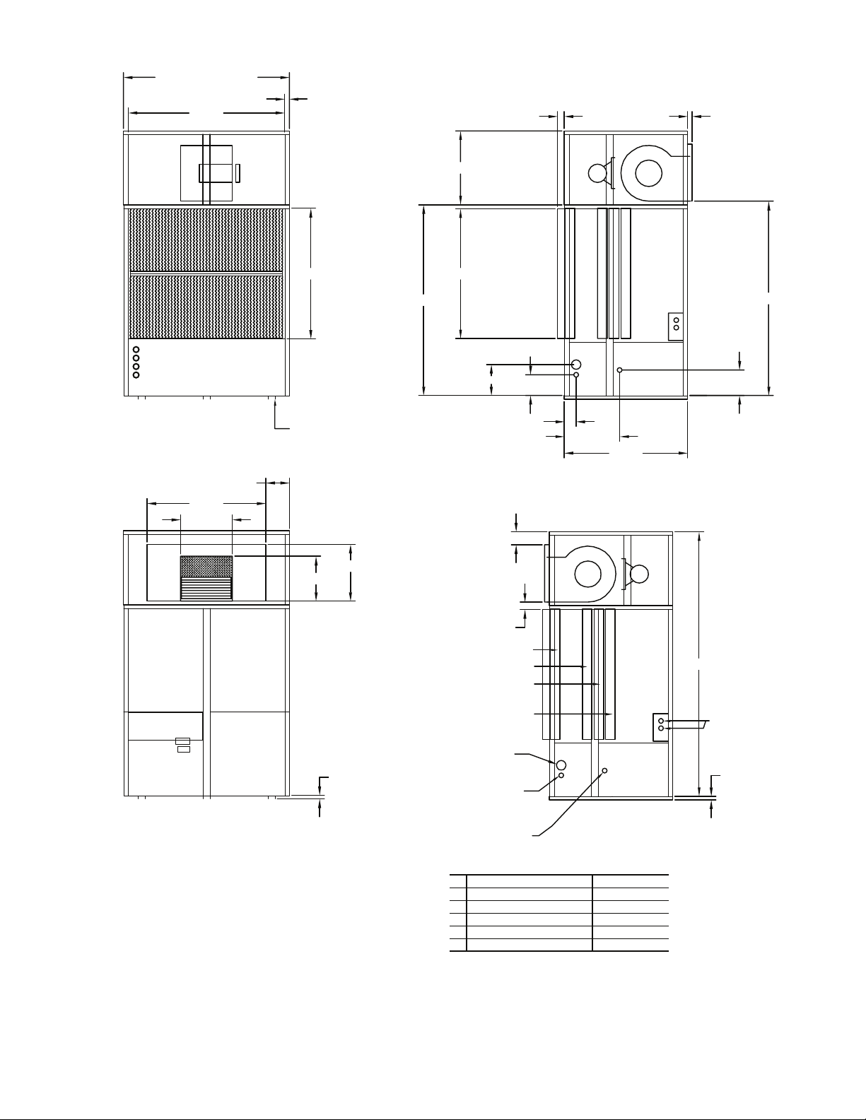
Fig. 5 — 50BVT,V,W034 (Low-Boy) Dimensions
a50-8202
NOTES:
1. Dimensions in inches.
2. All units are rear return airflow configuration.
3. Recommended minimum service clearances are as follows:
a. Front and rear — 30 in. (762 mm)
b. Left or right side — 65 in. (1651 mm) for coil removal
c. Side opposite coil removal — 20 in. (508 mm)
CONNECTIONS
REPLACEMENT FILTERS : EIGHT (8) AT 17 x 27 x 4 INCHES.
A WATER OUT 2-1/2 in. FPT
B WATER IN 2-1/2 in. FPT
C CONDENSATE DRAIN 1-1/4 in. FPT
D ECONOMIZER DRAIN 1-1/4 in. FPT
a50-8202.eps
8
REAR VIEW
RETURN AIR VIEW
LEFT SIDE VIEW
80.00
FRONT VIEW
54.38
8.75
15.00
13.00
31.00
COMPRESSOR
ACCESS
EVAPORATOR
ACCESS
EVAPORATOR
ACCESS
ELECTRICAL BOX
ACCESS
COMPRESSOR
ACCESS
BLOWER
SECTION
ACCESS
BLOWER
SECTION
ACCESS
EVAPORATOR
ACCESS
ELECTRICAL BOX
2.88
21.75
49.75
2.00
EVAPORATOR
ACCESS
BLOWER
SECTION
ACCESS
LEFT SIDE VIEW
FILTER ACCESS
ECONO COIL (OPTIONAL)
DIRECT EXPANSION
EVAPORATOR
REHEAT COIL (OPTIONAL)
STANDARD
DISCHARGE
REAR DISCHARGE
(OPTIONAL)
WATER IN
(ECONO COIL
OPTIONAL)
ELECTRICAL
81.50
BLOWER
SECTION
ACCESS
COMPRESSOR
ACCESS
COMPRESSOR
ACCESS
EVAPORATOR
ACCESS
EVAPORATOR
ACCESS
ELECTRICAL BOX
ACCESS
ELECTRICAL BOX
139.00
23.75
18.75
49.75
21.75
9.88
19.75
9.88
111.00
3.19
5.50
65.50 65.50
4.00
54.75
2.00 2.00
23.25
5.00
51.63
1.50
1.50
LIFTING SUPPORT RAIL
69.50
SHIPPING SECTION
69.50
SHIPPING SECTION
10.75
3.75
A
B
C
D
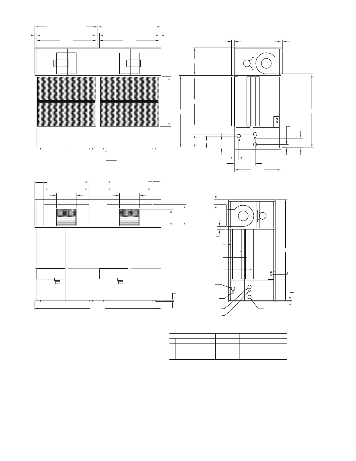
NOTES:
1. Dimensions in inches.
2. All units are rear return airflow configuration.
3. CV units are available with front or rear air supply.
4. VAV units (50BVW) are available with rear supply only.
5. Recommended minimum service clearances are as follows:
a. Front and rear — 30 in. (762 mm)
b. Left and right sides — 65 in. (1651 mm) for coil removal
CONNECTIONS
REPLACEMENT FILTERS : SIXTEEN (16) AT 17 x 27 x 4 INCHES.
UNIT SIZE 044 054 064
A WATER OUT 2-1/2 in. FPT 3 in. FPT 3 in. FPT
B WATER IN 2-1/2 in. FPT 3 in. FPT 3 in. FPT
C CONDENSATE DRAIN 1-1/4 in. FPT 1-1/4 in. FPT 1-1/4 in. FPT
D ECONOMIZER DRAIN 1-1/4 in. FPT 1-1/4 in. FPT 1-1/4 in. FPT
a50-8203
Fig. 6 — 50BVT,V,W044-064 (High-Boy) Dimensions
9
Fig. 7 — 50BVT,V,W044-064 (Low-Boy) Dimensions
CONNECTIONS
REPLACEMENT FILTERS : SIXTEEN (16) AT 17 x 27 x 4 INCHES.
UNIT SIZE 044 054 064
A WATER OUT 2-1/2 in. FPT 3 in. FPT 3 in. FPT
B WATER IN 2-1/2 in. FPT 3 in. FPT 3 in. FPT
C CONDENSATE DRAIN 1-1/4 in. FPT 1-1/4 in. FPT 1-1/4 in. FPT
D ECONOMIZER DRAIN 1-1/4 in. FPT 1-1/4 in. FPT 1-1/4 in. FPT
NOTES:
1. Dimensions in inches.
2. All units are rear return airflow configuration.
3. Recommended minimum service clearances are as follows:
a. Front and rear — 30 in. (762 mm)
b. Left and right sides — 65 in. (1651 mm) for coil removal
a50-8204
10
REAR VIEW
RETURN AIR VIEW
LEFT SIDE VIEW
80.00
FRONT VIEW
54.38
8.75
13.00
31.00
BLOWER
SECTION
ACCESS
EVAPORATOR
ACCESS
2.88
2.00
EVAPORATOR
ACCESS
BLOWER
SECTION
ACCESS
LEFT SIDE VIEW
FILTER ACCESS
ECONO COIL (Optional)
DIRECT EXPANSION
EVAPORATOR
REHEAT COIL (Optional)
STANDARD
DISCHARGE
REAR DISCHARGE
(Optional)
WATER IN
(ECONO COIL
OPTIONAL)
ELECTRICAL
81.50
BLOWER
SECTION
ACCESS
COMPRESSOR
ACCESS
COMPRESSOR
ACCESS
EVAPORATOR
ACCESS
EVAPORATOR
ACCESS
ELECTRICAL BOX
ACCESS
ELECTRICAL BOX
23.75
18.75
49.75
21.75
9.88
111.00
3.19
5.50
65.50
54.75
2.00
23.25
5.00
51.63
1.50
1.50
LIFTING SUPPORT RAIL
69.50
SHIPPING SECTION
10.75
E
F
A
B
C
D
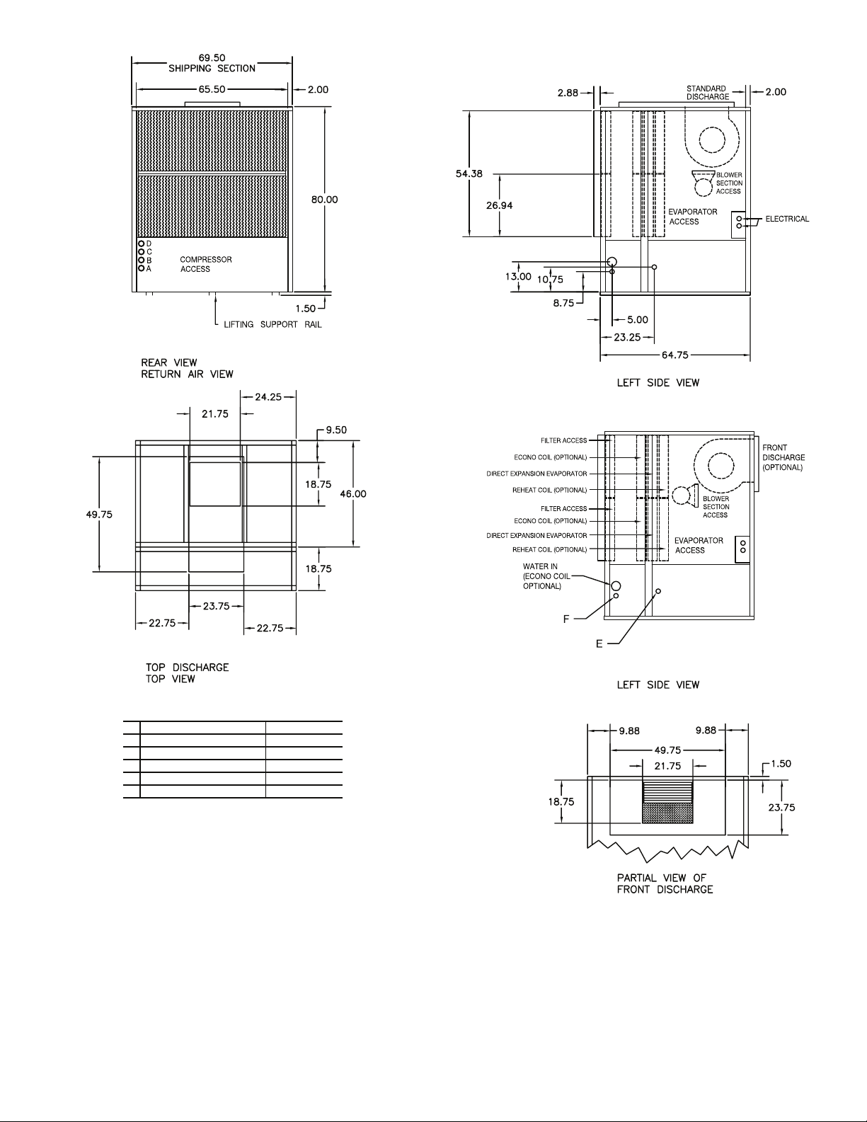
NOTES:
1. Dimensions in inches.
2. All units are rear return airflow configuration.
3. Constant volume units are available with front or rear air supply.
4. VAV units (50BVX) are available with rear supply only.
5. Recommended condenser match is ONE (1) 09DK034 (50/50 split).
6. Use proper piping practice for remote refr igerant connections. Refer to
Carrier System Design Manual Part 3.
7. Recommended minimum service clearances are as follows:
a. Front and rear — 30 in. (762 mm)
b. Left or right side — 65 in. (1651 mm) for coil removal
c. Side opposite coil removal — 20 in. (508 mm)
CONNECTIONS
REPLACEMENT FILTERS : EIGHT (8) AT 17 x 27 x 4 INCHES.
A LIQUID LINE CIRCUIT 1 7/8 in. OD
B LIQUID LINE CIRCUIT 2 7/8 in. OD
C DISCHARGE LINE CIRCUIT 1 1-1/8 in. OD
D DISCHARGE LINE CIRCUIT 2 1-1/8 in. OD
E CONDENSATE DRAIN 1-1/4 in. FPT
F ECONOMIZER DRAIN 1-1/4 in. FPT
a50-8205
Fig. 8 — 50BVU,X034 (High-Boy) Dimensions
11
a50-8206
Fig. 9 — 50BVU,X034 (Low-Boy) Dimensions
NOTES:
1. Dimensions in inches.
2. All units are rear return airflow configuration.
3. Recommended condenser match is ONE (1) 09DK034 (50/50 split).
4. Use proper piping practice for remote refrigerant connections. Refer to
Carrier System Design Manual Part 3.
5. Recommended minimum service clearances are as follows:
a. Front and rear — 30 in. (762 mm)
b. Left or right side — 65 in. (1651 mm) for coil removal
c. Side opposite coil removal — 20 in. (508 mm)
CONNECTIONS
REPLACEMENT FILTERS : EIGHT (8) AT 17 x 27 x 4 INCHES.
A LIQUID LINE CIRCUIT 1 7/8 in. OD
B LIQUID LINE CIRCUIT 2 7/8 in. OD
C DISCHARGE LINE CIRCUIT 1 1-1/8 in. OD
D DISCHARGE LINE CIRCUIT 2 1-1/8 in. OD
E CONDENSATE DRAIN 1-1/4 in. FPT
F ECONOMIZER DRAIN 1-1/4 in. FPT
a50-8206
12
REAR VIEW
RETURN AIR VIEW
LEFT SIDE VIEW
80.00
FRONT VIEW
54.38
8.75
13.00
31.00
COMPRESSOR
ACCESS
EVAPORATOR
ACCESS
EVAPORATOR
ACCESS
ELECTRICAL BOX
ACCESS
COMPRESSOR
ACCESS
BLOWER
SECTION
ACCESS
BLOWER
SECTION
ACCESS
EVAPORATOR
ACCESS
ELECTRICAL BOX
2.88
21.75
49.75
2.00
EVAPORATOR
ACCESS
BLOWER
SECTION
ACCESS
LEFT SIDE VIEW
FILTER ACCESS
ECONO COIL (OPTIONAL)
DIRECT EXPANSION
EVAPORATOR
REHEAT COIL (OPTIONAL)
STANDARD
DISCHARGE
REAR DISCHARGE
(OPTIONAL)
WATER IN
(ECONO COIL
OPTIONAL)
ELECTRICAL
81.50
BLOWER
SECTION
ACCESS
COMPRESSOR
ACCESS
COMPRESSOR
ACCESS
EVAPORATOR
ACCESS
EVAPORATOR
ACCESS
ELECTRICAL BOX
ACCESS
ELECTRICAL BOX
139.00
23.75
18.75
49.75
21.75
9.88
19.75
9.88
111.00
3.19
5.50
65.50 65.50
4.00
54.75
2.00 2.00
23.25
5.00
51.63
1.50
1.50
LIFTING SUPPORT RAIL
69.50
SHIPPING SECTION
69.50
SHIPPING SECTION
10.75
E
F
A
B
C
D
A
B
C
D
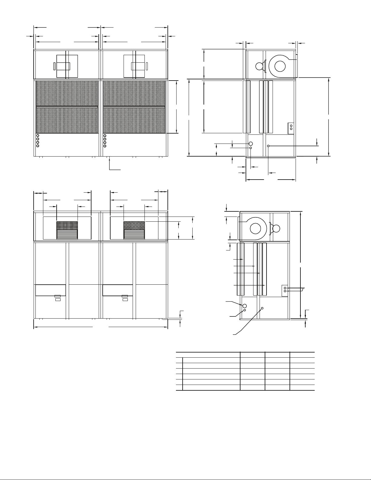
Fig. 10 — 50BVU,X044-064 (High-Boy) Dimensions
NOTES:
1. Dimensions in inches.
2. All units are rear return airflow configuration.
3. CV units are available with front or rear air supply.
4. VAV units (50BVX) are available with rear supply only.
5. Use proper piping practice for remote refrigerant connections. Refer to
Carrier System Design Manual Part 3.
6. Recommended minimum service clearances are as follows:
a. Front and rear — 30 in. (762 mm)
b. Left and right sides — 65 in. (1651 mm) for coil removal
CONNECTIONS
REPLACEMENT FILTERS : SIXTEEN (16) AT 17 x 27 x 4 INCHES.
UNIT SIZE 044 054 064
A LIQUID LINE CIRCUIT 1, 2 7/8 in. OD 7/8 in. OD 7/8 in. OD
B LIQUID LINE CIRCUIT 3, 4 7/8 in. OD 7/8 in. OD 7/8 in. OD
C DISCHARGE LINE CIRCUIT 1, 2 1-1/8 in. OD 1-1/8 in. OD 1-1/8 in. OD
D DISCHARGE LINE CIRCUIT 3, 4 1-1/8 in. OD 1-1/8 in. OD 1-1/8 in. OD
E CONDENSATE DRAIN 1-1/4 in. FPT 1-1/4 in. FPT 1-1/4 in. FPT
F ECONOMIZER DRAIN 1-1/4 in. FPT 1-1/4 in. FPT 1-1/4 in. FPT
a50-8207
13
a50-8208
NOTES:
1. Dimensions in inches.
2. All units are rear return airflow configuration.
3. Use proper piping practice for remote refrigerant connections. Refer to
Carrier System Design Manual Part 3.
4. Recommended minimum service clearances are as follows:
a. Front and rear — 30 in. (762 mm)
b. Left and right sides — 65 in. (1651 mm) for coil removal
CONNECTIONS
REPLACEMENT FILTERS : SIXTEEN (16) AT 17 x 27 x 4 INCHES.
UNIT SIZE 044 054 064
A LIQUID LINE CIRCUIT 1, 2 7/8 in. OD 7/8 in. OD 7/8 in. OD
B LIQUID LINE CIRCUIT 3, 4 7/8 in. OD 7/8 in. OD 7/8 in. OD
C DISCHARGE LINE CIRCUIT 1, 2 1-1/8 in. OD 1-1/8 in. OD 1-1/8 in. OD
D DISCHARGE LINE CIRCUIT 3, 4 1-1/8 in. OD 1-1/8 in. OD 1-1/8 in. OD
E CONDENSATE DRAIN 1-1/4 in. FPT 1-1/4 in. FPT 1-1/4 in. FPT
F ECONOMIZER DRAIN 1-1/4 in. FPT 1-1/4 in. FPT 1-1/4 in. FPT
Fig. 11 — 50BVU,X044-064 (Low-Boy) Dimensions
14
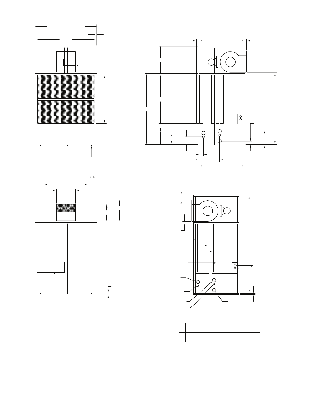
Fig. 12 — 50BVC,J,Q020-028 with Optional Waterside Economizer Dimensions
NOTES:
1. Dimensions in inches [mm].
2. Refer to base unit certified drawing for additional unit dimensions, service
clearance, and alternate airflow configurations.
a50-7306ef
15
Fig. 13 — 50BVC,J,Q034 with Optional Waterside Economizer Dimensions
NOTES:
1. Dimensions in inches [mm].
2. Refer to base unit certified drawing for additional unit dimensions, service
clearances, and alternate airflow configurations.
a50-7307ef
16
*
*
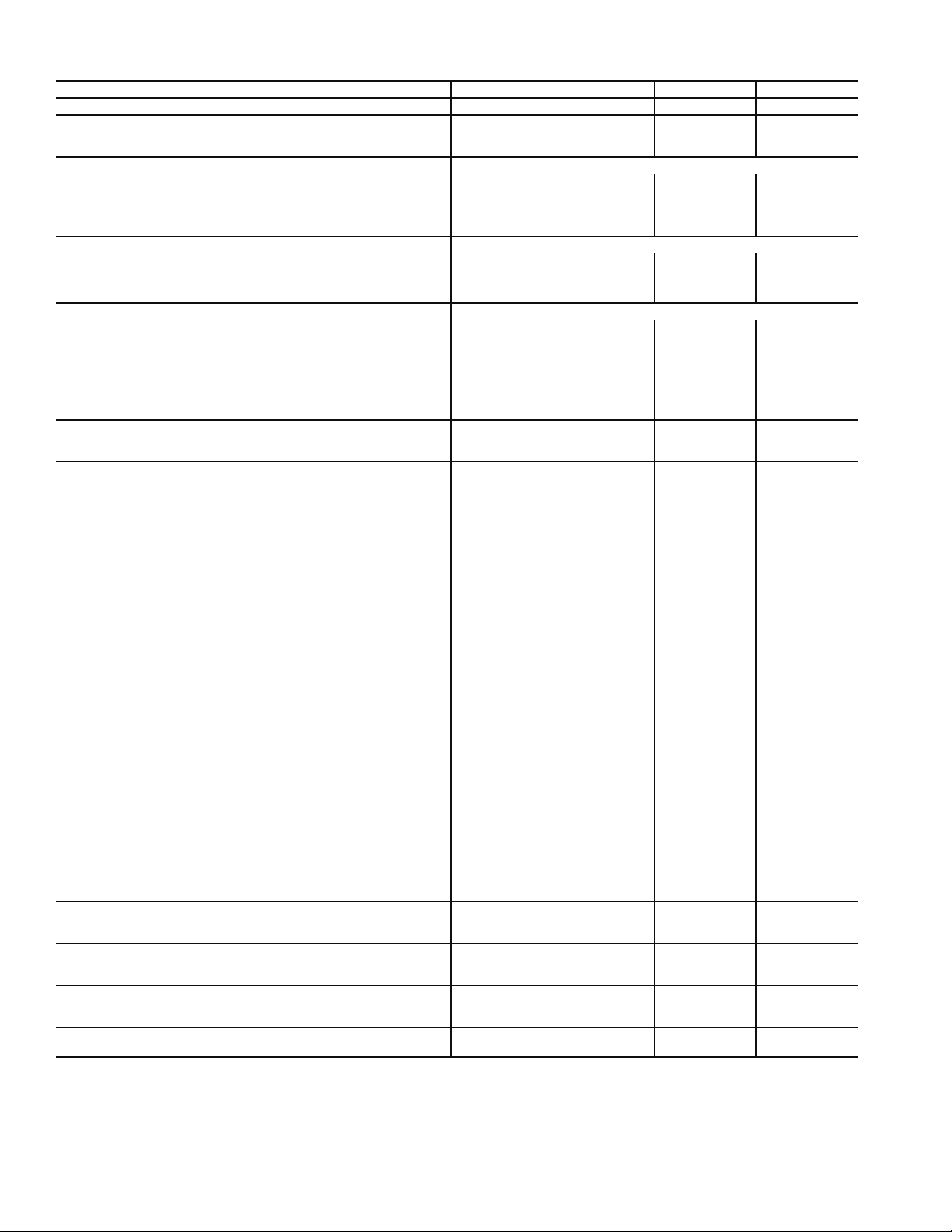
a50-8235
Shipping Weights (lb)
*High-boy/low-boy.
50BVT,U,V,W,X UNIT
HIGH-BOY UNIT LOW-BOY UNIT
034 044 054 064 034 044 054 064
MAIN AIR CONDITIONING SECTION (EACH)
NUMBER OF SECTIONS 12221222
SECTION WEIGHT 1450 1175 1550 1575 2100 1825 2200 2225
REHEAT COIL OPTION 40 40 40 40 40 40 40 40
FILTER/ECONOMIZER SECTION (EACH)
NUMBER OF SECTIONS 12221222
FILTER SECTION 310 310 310 310 310 310 310 310
ECONOMIZER OPTION 200 200 200 200 200 200 200 200
FAN SECTION (EACH)
NUMBER OF SECTIONS 1222
INCLUDED IN
AIR CONDITIONING SECTION
FAN SECTION 650 650 650 650
TOTAL UN IT
NUMBER OF SECTIONS 36662444
UNIT WITH OPTIONS 2650 4750 5500 5550 2650 4750 5500 5550
Size 034 Units
Size 044-064 Units
Fig. 14 — Modular Shipping Weights — 50BVT,U,V,W,X
17
Table 3A — Physical Data — 50BVC,E,J,K,Q
LEGEND *R-410A models.
UNIT 50BVC,E,J,K,Q 020 024 028 034
NOMINAL CAPACITY (Tons) 18 20 25 30
OPERATING WEIGHT (lb)
50BVC,Q…50BVJ 1192…1227 1378…1413 1428…1473 1680…1725
50BVE…50BVK 1110…1145 1290…1325 1320…1365 1520…1565
COMPRESSOR Copeland Scroll
Quantity 2222
Number of Refrigerant Circuits 2222
Oil (ounces) Ckt 1…Ckt 2 85…85 110…110 110…110 140…140
REFRIGERANT TYPE R-22 or R-410A
Expansion Device TXVTXVTXVTXV
Operating Charge (lb) Ckt 1…Ckt 2 8.1…8.1 9.1…9.1 9.1…9.1 18.0…18.0
CONDENSER (50BVC,Q,J only) Tube-in-Tube Coaxial
Quantity of Manifolded Circuits 2222
Nominal Flow Rate (GPM) 54 60 75 90
Water Flow Range (GPM) 36-72 40-80 50-100 60-120
Max. Water Working Pressure (PSIG) 400 400 400 400
Max. Refrig. Working Pressure (PSIG) 450 (600*) 450 (600*) 450 (600*) 450 (600*)
Min. Entering Water Temp. (°F) 50 50 50 50
Max. Entering Water Temp. (°F) 110 110 110 110
Waterside Volume (gal) 3.6 4.0 5.0 6.0
EVAPORATOR COIL
Rows…Fins/in. 3…14 3…14 3…14 3…14
Total Face Area (sq ft) 18.1 18.1 18.1 22.0
EVAPORATOR FAN
Quantity…Size 2…15x15 2…15x15 2…15x15 2…15x15
Type Drive Belt Belt Belt Belt
Nominal CFM 7200 8000 10,000 12,000
Std Motor Qty…HP…Frame Size 2…1.5…56 2…2…56H 2…3…56HZ 2…5…56HZ
Alt 1 Motor Qty…HP…Frame Size 2…2…56H 2…3…56HZ 2…5…56HZ —
Alt 2 Motor Qty…HP…Frame Size 2…3…56HZ 2…5…56HZ — —
Alt 3 Motor Qty…HP…Frame Size 2…5…56HZ — — —
Motor Nominal RPM (1.5, 2, 3, HP) 1725 1725 1725 —
Motor Nominal RPM (5 HP) 3450 3450 3450 3450
Fan Drive RPM Range
Std Fan Drive (1.5, 2, 3 HP) 753-952 753-952 753-952 —
Std Fan Drive (5 HP) 967-1290 967-1290 967-1290 967-1290
Med Static Fan Drive (1.5, 2, 3 HP) 872-1071 872-1071 872-1071 —
Motor Bearing Type Ball Ball Ball Ball
Maximum Allowable RPM 1300 1300 1300 1300
Motor Pulley Pitch Diameter
Std Fan Drive (1.5, 2, 3 HP) 3.7-4.7 3.7-4.7 3.7-4.7 —
Std Fan Drive (5 HP) 2.9-3.9 2.9-3.9 2.9-3.9 2.9-3.9
Med Static Fan Drive (1.5, 2, 3 HP) 4.3-5.3 4.3-5.3 4.3-5.3 —
Motor Shaft Diameter (in.) (1.5, 2 HP)
5
/
8
5
/
8
——
Motor Shaft Diameter (in.) (3, 5 HP)
7
/
8
7
/
8
7
/
8
7
/
8
Belt, Qty…Type…Length (in.)
Std Fan Drive (1.5, 2 HP) 1…B…39 1…B…39 — —
Std Fan Drive (3 HP) 2…B…39 2…B…39 2…B…39 —
Std Fan Drive (5 HP) 2...BX…42 2...BX…42 2...BX…42 2...BX…42
Med Static Fan Drive (1.5, 2 HP) 1…B…40 1…B…40 — —
Med Static Fan Drive (3 HP) 2…B…40 2…B…40 2…B…40 —
Pulley Center Line Distance (in.) 10.1…10.9 10.1…10.9 10.1…10.9 10.1…10.9
Speed Change Per Full Turn of
Moveable Pulley Flange (RPM)
Std Fan Drive (1.5, 2, 3 HP) 33 33 33 —
Std Fan Drive (5 HP) 54 54 54 54
Med Static Fan Drive (1.5, 2, 3 HP) 33 33 33 —
Fan Shaft Diameter (in.) 1111
HIGH PRESSURE SWITCHES (PSIG)
Cutout 380 (420*) ± 10 380 (420*) ± 10 380 (420*) ± 10 380 (420*) ± 10
Reset (Auto) 300 (420*) ± 15 300 (420*) ± 15 300 (420*) ± 15 300 (420*) ± 15
LOW PRESSURE SWITCHES (PSIG)
Cutout 20 (40*) ± 3 20 (40*) ± 3 20 (40*) ± 3 20 (40*) ± 3
Reset (Auto) 40 (60*) ± 5 40 (60*) ± 5 40 (60*) ± 5 40 (60*) ± 5
REMOTE REFRIGERANT CONNECTIONS
(50BVE,K Only)
Discharge (Hot Gas) Connection (in.) Qty…Size 2…1
1
/
8
2…1
1
/
8
2…1
1
/
8
2…1
1
/
8
Liquid Connection (in.) Qty…Size 2…
7
/
8
2…
7
/
8
2…
7
/
8
2…
7
/
8
RETURN AIR FILTERS
Quantity…Size (in.) 4…20x34.5x1 4…20x34.5x1 4…20x34.5x1 4…30x34.5x1
TXV — Thermostatic Expansion Valve
18
Table 3B — Physical Data — 50BVT,U,V,W,X
UNIT 50BVT,U,V,W,X 034 044 054 064
NOMINAL CAPACITY (Tons) 30 40 50 60
OPERATING WEIGHT (lb)
50BVT,V…50BVW 2580…2645 4334…4404 5198…5298 5230…5330
50BVU…50BVX 2420…2485 4094…4164 4938…5038 4970…5070
COMPRESSOR Copeland Scroll
Quantity 2444
Number of Refrigerant Circuits 2444
Oil (oz.)
Circuit 1…Circuit 2 140…140 110…110 140…140 140…140
Circuit 3…Circuit 4 — 110…110 140…140 140…140
REFRIGERANT TYPE R-22
Expansion Device TXV TXV TXV TXV
Operating Charge (lb)
Circuit 1…Circuit 2 18.0…18.0 10.0…10.0 18.0…18.0 18.0…18.0
Circuit 3…Circuit 4 — 10.0…10.0 18.0…18.0 18.0…18.0
CONDENSER (50BVT,V,W only) Tube-in-Tube Coaxial
Quantity of Manifolded Circuits 2444
Nominal Flow Rate (GPM) 90 120 150 180
Water Flow Range (GPM) 60-120 80-160 100-200 120-240
Max. Water Working Pressure (PSIG) 400 400 400 400
Max. Refrig. Working Pressure (PSIG) 450 450 450 450
Min. Entering Water Temp. (°F) 50 50 50 50
Max. Entering Water Temp. (°F) 110 110 110 110
Waterside Volume (gal) 6.0 9.0 11.3 13.5
EVAPORATOR COIL
Rows…Fins/in. 4…12 3…12 4…12 4…12
Total Face Area (sq ft) 23.2 46.4 46.4 46.4
EVAPORATOR FAN
Quantity…Size 1…18x18 2…18x18 2…18x18 2…18x18
Type Drive Belt Belt Belt Belt
Nominal CFM 12,000 16,000 20,000 24,000
Motor Option 1 Qty…HP…Frame Size 1…7.5…213T 2…7.5…213T 2…7.5…213T 2…7.5…213T
Motor Option 2 Qty…HP…Frame Size 1…10…215T 2…10…215T 2…10…215T 2…10…215T
Motor Option 3 Qty…HP…Frame Size 1…15…254T 2…15…254T 2…15…254T 2…15…254T
Motor Option 4 Qty…HP…Frame Size 1…20…256T — 2…20…256T 2…20…256T
Motor Nominal RPM 1750 1750 1750 1750
Fan Drive RPM Range
Standard (7.5 HP) 780-960 780-960 780-960 780-960
Standard (10, 15, 20 HP), Med Static (7.5 HP) 805-991 805-991 805-991 805-991
Med Static (10, 15, 20 HP), High Static (7.5 HP) 960-1146 960-1146 960-1146 960-1146
High Static (10, 15, 20 HP) 1119-1335 1119-1335 1119-1335 1119-1335
Motor Bearing Type Ball Ball Ball Ball
Maximum Allowable RPM 1450 1450 1450 1450
Motor Pulley Pitch Diameter
Std Fan Drive (7.5 HP) 5.2-6.4 5.2-6.4 5.2-6.4 5.2-6.4
Std Fan Drive (10, 15, 20 HP), Med Static (7.5 HP) 4.8-6.0 4.8-6.0 4.8-6.0 4.8-6.0
Med Static Fan Drive (10, 15, 20 HP), High Static (7.5 HP) 5.8-7.0 5.8-7.0 5.8-7.0 5.8-7.0
High Static Fan Drive (10, 15, 20 HP) 5.8-7.0 5.8-7.0 5.8-7.0 5.8-7.0
Motor Shaft Diameter (in.) (7.5, 10 HP) 1
3
/
8
1
3
/
8
1
3
/
8
1
3
/
8
Motor Shaft Diameter (in.) (15, 20 HP) 1
5
/
8
1
5
/
8
1
5
/
8
1
5
/
8
Belt, Qty…Type…Length (in.)
Std Fan Drive (7.5 HP) 2…B…48 2...B...48 2…B…48 2…B…48
Std Fan Drive (10, 15, 20 HP), Med Static (7.5 HP) 2…B…46 2…B…46 2…B…46 2…B…46
Med Static Fan Drive (10, 15, 20 HP), High Static 7.5 HP) 2…B…48 2…B…48 2…B…48 2…B…48
High Static Fan Drive (10, 15, 20 HP) 2…B…45 2…B…45 2…B…45 2…B…45
Pulley Center Line Distance (in.) 10.2-11.4 10.2-11.4 10.2-11.4 10.2-11.4
Speed Change Per Full Turn of Moveable Pulley Flange (RPM)
Std Fan Drive (7.5 HP) 36 36 36 36
Std Fan Drive (10, 15, 20 HP), Med Static (7.5 HP) 31 31 31 31
Med Static Fan Drive (10, 15, 20 HP), High Static (7.5 HP) 31 31 31 31
High Static Fan Drive (10, 15, 20 HP) 36 36 36 36
Fan Shaft Diameter (in.) 1
7
/
16
1
7
/
16
1
7
/
16
1
7
/
16
HIGH PRESSURE SWITCHES (PSIG)
Cutout 380 ± 10 380 ± 10 380 ± 10 380 ± 10
Reset (Auto) 300 ± 15 300 ± 15 300 ± 15 300 ± 15
LOW PRESSURE SWITCHES (PSIG)
Cutout 20 ± 3 20 ± 3 20 ± 3 20 ± 3
Reset (Auto) 40 ± 5 40 ± 5 40 ± 5 40 ± 5
REMOTE REFRIGERANT CONNECTIONS (50BVU,X Only)
Discharge (Hot Gas) Connection (in.) Qty…Size 2…1
1
/
8
4…1
1
/
8
4…1
1
/
8
4…1
1
/
8
Liquid Connection (in.) Qty…Size 2…
7
/
8
4…
7
/
8
4…
7
/
8
4…
7
/
8
RETURN AIR FILTERS
Quantity…Size (in.) 8…17x27x4 16…17x27x4 16…17x27x4 16…17x27x4
19
ACOUSTICAL CONSIDERATIONS — Proper acoustical
considerations are a critical part of every system’s design and
operation. Each system design and installation should be
reviewed for its own unique requirements. For job specific
requirements, contact an acoustical consultant for guidance and
recommendations.
In general, to reduce noise, consider the following:
• Locate mechanical room and ducts away from noise
sensitive locations. Whenever possible, work with the
architect to locate the equipment rooms around the
perimeters of restrooms, hallways, fire escapes, stair
wells, etc., to reduce noise transmission. This allows not
only for isolation from radiated sound but also enables
the contractor to route duct systems around sensitive
locations.
• Construct the equipment room of concrete block or use a
double offset stud wall with interwoven insulation. Seal
all penetrations.
• Design the system for low total static pressure.
• Use suitable vibration isolation pads or isolation springs
according to the design engineer's specifications.
• A flexible canvas duct connector is recommended on
both the supply and return air sides of units to be
connected to system ductwork.
• Use a minimum of 15 ft of return ductwork between the
last air terminal or diffuser and the unit.
• Insulate supply and return ducts with 2-in., 3-lb density
insulation.
• Round duct is recommended. If rectangular ductwork is
used, keep aspect ratios as small as possible (i.e., as close
to square as possible).
• Avoid any direct line of sight from return air grilles
into the unit's return. If return air is to be ducted to an
equipment room, an elbow should be installed within the
equipment room.
• Running a return air drop to near the floor of the room
will aid in sound attenuation.
• Do not exceed the recommended supply duct velocity of
2,000 fpm.
• Do not exceed the recommended return duct velocity of
1,000 fpm.
• Use turning vanes on 90-degree elbows.
• Place isolation springs under each corner and under each
compressor if utilized.
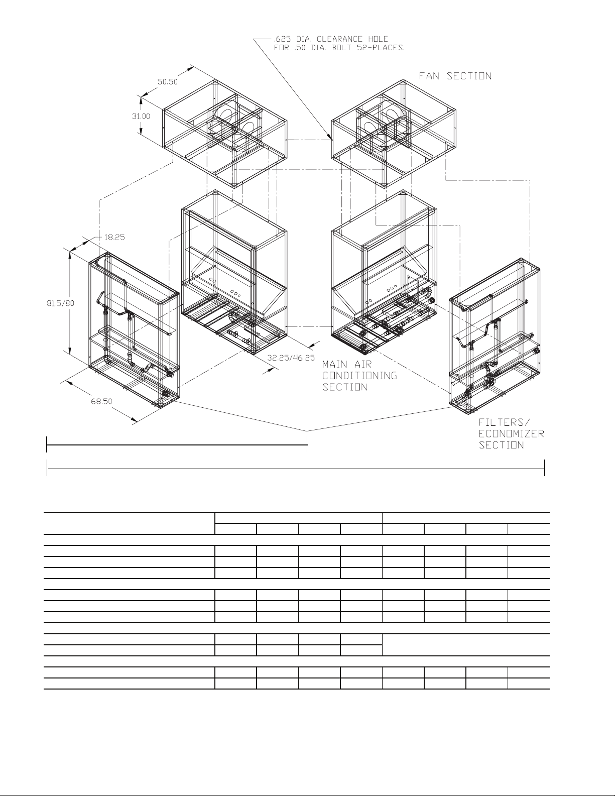
ASSEMBLING MODULAR UNITS — 50BVT,U,V,W,X
30 to 60 ton units ship in the number of pieces shown in Table
2. Reassemble the unit. Use the loose hardware provided in the
main air-conditioning section and the instructions below.
1. The filter/economizer section ships bolted to the main air-
conditioning section and can be removed in the field.
When reattaching the filter/economizer section to the
main air-conditioning section, place the filter side of the
filter/economizer section facing out and away from the
main air conditioning section.
2. If the unit has 2 filter/economizer and 2 main air-
conditioning sections (40 through 60 ton units), bolt the
remaining filter/economizer section and main air-
conditioning section together, as in Step 1.
3. For units with 2 filter/economizer and 2 main air-
conditioning sections, use the provided unions to assem-
ble the water connections between the 2 additional
sections joined in Step 2.
4. For units with multiple air conditioning sections, connect
the condensate drain hoses from the “B” side of the unit
to the drain manifold on the “A” side of the unit.
5. For unit sizes 044-064, connect power wiring from the
main terminal block in the “A” side of the unit to the
power terminal block in the “B” side of the unit.
6. For VAV units only, connect the plenum tubing, coiled
behind the VAV control panel, to the bulkhead fittings
located in the discharge of the supply fan. This connects
the high pressure supply to the high side of the duct high
static pressure switch.
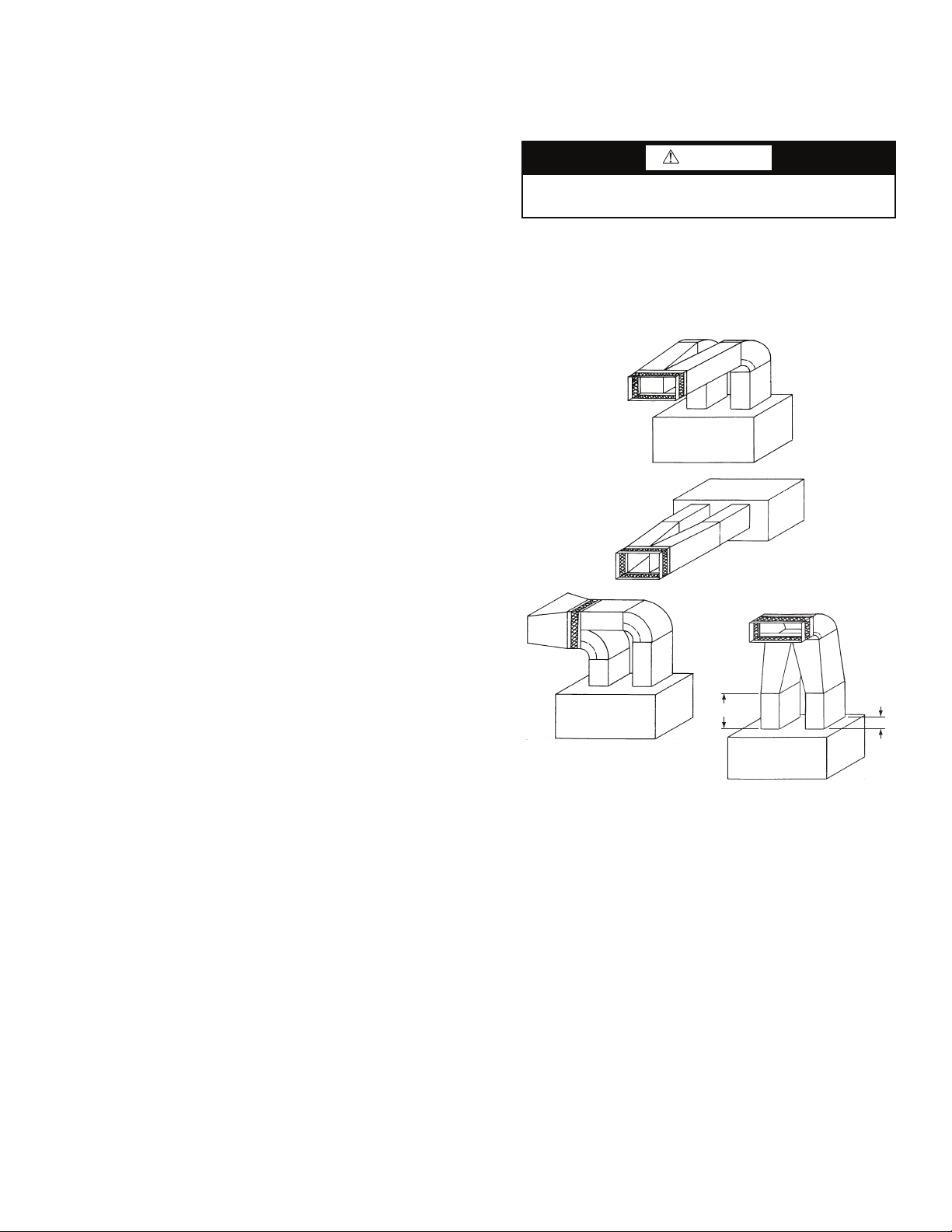
Step 3 — Install Ductwork — The VAV units must
use a “pair of pants” configuration as shown in Fig. 15. Refer
to the Carrier System Design Manual or ASHRAE (American
Society of Heating, Refrigerating and Air Conditioning Engi-
neers) standards for the recommended duct connection to unit
with 2 fans.
A supply air outlet collar and return air duct flange are pro-
vided on all units to facilitate duct connections. Refer to dimen-
sional drawings (Fig. 2-14) for connection sizes and locations.
A flexible canvas duct connector is recommended on both
supply and return air sides of the units to be connected to the
system ductwork.
All metal ductwork should be adequately insulated to avoid
heat loss or gain and to prevent condensation from forming on
the duct walls. Uninsulated ductwork is not recommended, as
the unit's performance will be adversely affected.
Do not connect discharge ducts directly to the blower
outlet(s). The factory filter should be left in place on a free
return system.
If the unit will be installed in a new installation, the duct
system should be designed in accordance with the System De-
sign Manual, Part 2 and with ASHRAE (American Society of
Heating, Refrigeration and Air Conditioning Engineers) proce-
dures for duct sizing. If the unit will be connected to an existing
duct system, check that the existing duct system has the capaci-
ty to handle the required airflow for the unit application at an
CAUTION
Remove all shipping blocks, if any, under blower housing
or damage to the fan may occur.
Fig. 15 — Typical Fan Discharge Connections for
Multiple Fan Units
NOTE: A = 1
1
/
2
to 2
1
/
2
B
A
B
a50-8357.eps
20
acceptable system static pressure. If the existing duct system is
too small, larger ductwork must be installed.
The duct system and diffusers should be sized to handle the
design airflow volumes quietly. To maximize sound attenuation
of the unit's blower(s), the supply and return air plenums should
be insulated for a length of at least 15 ft from the unit. Direct line
of sight from return air grilles into the unit's return should be
avoided. If return air is to be ducted to an equipment room, an
elbow should be installed within the equipment room. Running a
return air drop to near the floor of the room will aid in sound
attenuation. Avoid transmitting vibrations generated by the
movement of air in the ducting to the walls of the building. This
is especially important where ductwork penetrates walls. The
maximum recommended return air velocity is 1,000 fpm. Lower
return air velocities will result in lower sound power levels. The
use of round supply duct plenums should be considered, as it
will significantly reduce low frequency sound at the equipment
room. If rectangular supply plenums are used, the aspect ratio of
the duct should be kept as small as possible (i.e., as close to
square as possible). The large, flat surface areas associated with
large aspect ratio duct systems will transmit sound to the space,
and the potential for duct-generated noise is increased. The max-
imum recommended supply air duct velocity is 2,000 fpm.
Units with two fans should have a properly designed “pair
of pants” duct connection. An adequate straight length of
ducting from the unit should be allowed before elbows are
installed. If connecting an elbow directly to the fan outlet, a
minimum straight length of 2 fan diameters from the fan outlet
is recommended. Elbows should turn in the direction of fan ro-
tation, if possible. Abrupt turns will generate air turbulence and
excessive noise. Turning vanes should be used in all short radi-
us bends. Ensure that ducting does not obstruct access to the
unit for routine servicing.
DUCT STATIC PRESSURE PROBE AND TUBING (VAV
Only) — On VAV systems, the duct static pressure sensor and
tubing are field-mounted. The sensor tubing sensing point
should be located near the end of the main supply trunk duct in
a position free from turbulence effects and at least 10 duct di-
ameters downstream and 4 duct diameters upstream from any
major transitions or branch take-offs. Incorrectly placing the
sensing point could result in improper operation of the entire
VAV s y st e m .
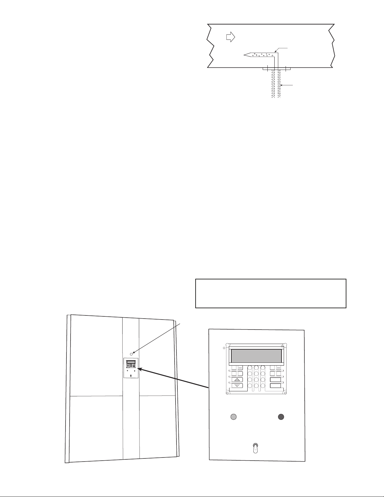
Install the factory-supplied duct static pressure probe with
the tip facing into the airflow. See Fig. 16.
Use
1
/
4
-in. OD approved polyethylene tubing for up to
50 ft (
3
/
8
-in. OD for 50 to 100 ft) to connect the probe to the
bulkhead fitting mounted above the unit display panel
(Fig. 17). Carefully route the tubing from the probe to this
bulkhead fitting.
The static pressure control should be adjusted so that, at full
airflow, all of the remote VAV terminal boxes receive the
minimum static pressure required plus any downstream resis-
tance. Control the system to the lowest static pressure set point
that will satisfy airflow requirements. Lower static pressure set
points reduce total required brake horsepower and reduce
generated sound levels.
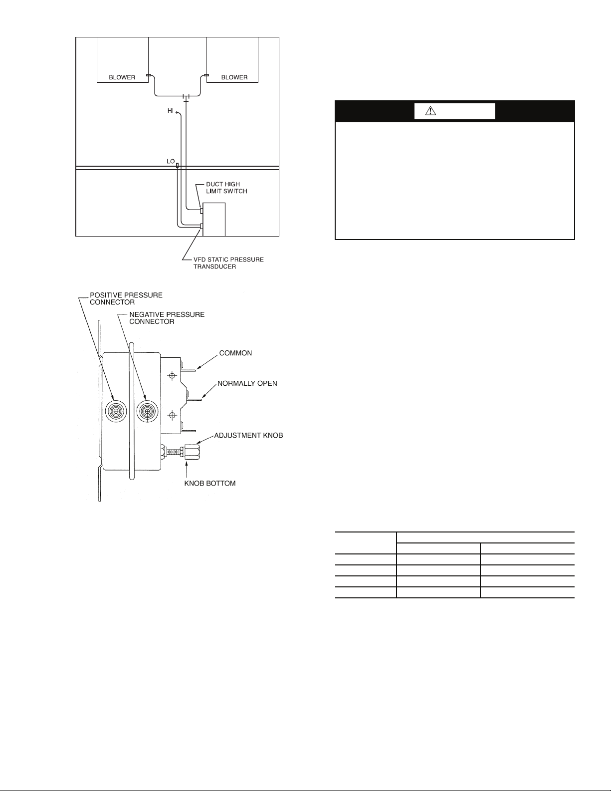
DUCT HIGH-STATIC (DHS) LIMIT SWITCH (VAV
Only) — The duct high static limit switch is a mechanical
safety that prevents duct overpressurization. The switch is lo-
cated on the side of the VAV low voltage control panel
(Fig. 18) and is factory set at 3 in. wg. To make an adjustment
using an accurate differential pressure gage, connect low side
and high side to gage and pressure source. Place a voltmeter
across common and normally open contacts. Rotate the adjust-
ment knob (Fig. 19) clockwise to increase pressure setting and
counterclockwise to decrease pressure setting. When the bot-
tom of the adjustment knob is approximately
1
/
8
-in. from the
switch body, the switch will trip at approximately 3 in. wg.
IMPORTANT: Use tubing that complies with local codes.
Improper location or installation of the supply duct pres-
sure tubing will result in unsatisfactory unit operation and
poor performance.
AIRFLOW
PROBE
TUBING
Fig. 16 — Duct Static Pressure Probe
(P/N 39EK20462)
a50-7138ef
WARNING
ALARM
REMOTE
LOCAL
OFF
ENTER
CLEAR
SRVC
HISTALGO
TEST
ALRM
3
6
9
1
2
4
5
7
8
0
.
–
STAT
SET
SCHD
EXPN
EDIT
WARNING
ALARM
REMOTE
LOCAL
OFF
ENTER
CLEAR
SRVC
HIST ALGO
TEST
ALRM
3
6
9
1
2
4
5
7
8
0
.
–
STAT
SET
SCHD
EXPN
EDIT
DUCT STATIC
PRESSURE
PROBE
BULKHEAD
FITTING
Fig. 17 — Display Panel Location on Unit Front Panel
a50-7267ef
21
Step 4 — Make Piping Connections
CONDENSER WATER PIPING (Water-Cooled Only) —
Always follow national and local codes when installing water
piping to ensure a safe and proper installation. Connections to
the unit should incorporate vibration eliminators to reduce
noise and vibration to the building, and shutoff valves to facili-
tate servicing.
Prior to connecting the unit(s) to the condenser water
system, the system should be flushed to remove foreign
material that could cause condenser fouling. Install a screen
strainer with a minimum of 20 mesh ahead of the condenser
inlet to prevent condenser fouling and internal condenser tube
damage from foreign material.
Supply and return water piping must be at least as large as
the unit connections, and larger for long runs. Refer to the
System Design Manual, Part 3, and standard piping practice,
when sizing, planning, and routing water piping. See dimen-
sion drawings (Fig. 2-14) for water connection sizes and
locations.
Units are furnished standard with a copper heat exchanger.
A cupronickel heat exchanger is also available as a
factory-installed option. Copper is adequate for closed loop
systems where good quality water is available. In conditions
where scale formation or water treatment is questionable, the
optional cupronickel heat exchanger should be used. Where the
water is especially corrosive or could lead to excessive fouling,
intermediate plate frame heat exchangers are recommended.
The unit is capable of operating with entering water temper-
atures as low as 50 F, without the need for head pressure
control. If the entering water temperature is expected to be
lower, or more stable unit operation is desired, a field-supplied
water-regulating valve may be used.
This unit has multiple independent refrigerant circuits with
separate condensers. The individual condensers are manifolded
together on the waterside to provide easy, single-point water
connections. In order to achieve proper head pressure control
when a water-regulating valve is used, a temperature-actuated
valve is recommended. This allows any of the independent
refrigerant circuits to operate while still modulating condenser
water flow in response to loop water temperature.
A glycol solution should be used if ambient temperatures
are expected to fall below freezing or if the loop water temper-
ature is below 50 F while operating in the reverse cycle heating
mode (heat pump units only). Refer to Table 4, which
lists freezing points of glycol at different concentrations. A
minimum concentration of 20% is recommended. Water
pressure drop will increase and unit performance will decrease
with increasing glycol concentrations.
Units with factory-installed waterside economizers have
cooling water passing through the economizer and condenser
in series while operating in the economizer mode. During
normal operation, water bypasses the economizer coil.
Table 4 — Glycol Freezing Points
All manual flow valves used in the system should be of the
ball valve design. Globe or gate valves must not be used due to
high pressure drops and poor throttling characteristics.
Do not exceed recommended condenser fluid flow rates
shown in Tables 5A and 5B. Serious damage or erosion of the
heat exchanger tubes could occur. Piping systems should not
exceed 10 fps fluid velocities to ensure quietness and tube wall
integrity. Refer to Tables 5A and 5B for condenser water pres-
sure drop versus flow rate. Flow rates outside of the published
range should not be used.
Ball valves should be installed in the supply and return lines
for unit isolation and water flow balancing.
CAUTION
Galvanized pipe or fittings are not recommended with
50BV units due to the possibility of galvanic corrosion
caused by dissimilar metals. When selecting piping
materials, use only approved piping materials that meet
applicable codes and that will handle the temperatures and
pressures that may be experienced in the application.
Piping systems will sweat if low temperature fluid is used
in the system. For these applications, supply and return
water piping should be insulated to protect from condensa-
tion damage. The minimum recommended entering water
temperature to the unit is 50 F.
% GLYCOL
FREEZE POINT (° F)
Ethylene Glycol Proplylene Glycol
20 18 19
30 79
40 –7 –5
50 –28 –27
Fig. 19 — DHS Limit Switch (P/N 190060)
a50-7268tf
Fig. 18 — DHS Pressure Limit Location
a50-8253
 Loading...