


48/50P2,P3,P4,P5030-100 Low Ambient Operation MOTORMASTER® V Control Accessory 50/60 Hz
Installation Instructions
Part Numbers: CRLOWAMB033A00 THROUGH CRLOWAMB038A00
CONTENTS
Page SAFETY CONSIDERATIONS . . . . . . . . . . . . . . . . . . . . . . 1 GENERAL . . . . . . . . . . . . . . . . . . . . . . . . . . . . . . . . . . . . . . 1-3
INSTALLATION . . . . . . . . . . . . . . . . . . . . . . . . . . . . . . . . 3-12 Pre-Installation. . . . . . . . . . . . . . . . . . . . . . . . . . . . . . . . . . . 3
Step 1 — Install Field-Fabricated Wind Baffles . . . 3
Step 2 — Mounting and Electrical Connections for Motormaster® V Control . . . . . . . . . . . . . . . . . . . . 5
Step 3 — Configure Motormaster V Control . . . . . 11
Step 4 — Test Motormaster V Control . . . . . . . . . . . 11
START-UP . . . . . . . . . . . . . . . . . . . . . . . . . . . . . . . . . . . . 11-13 TROUBLESHOOTING. . . . . . . . . . . . . . . . . . . . . . . . . 13-15
SAFETY CONSIDERATIONS
Installation, start-up, and servicing of this equipment can be hazardous due to system pressures, electrical components, and equipment location (roofs, elevated structures, etc.).
Only trained, qualified installers and service technicians should install, start up, and service this equipment.
When working on this equipment, observe precautions in the literature and on tags, stickers, and labels attached to the equipment and any other safety precautions that may apply.
 WARNING
Open all remote disconnects before servicing this equipment. Electrical shock could result in personal injury.
GENERAL
This book contains instructions for the installation, start-up, and service of the Motormaster V (MMV) control on 48/50P030-100 units.
The Motormaster V control is a motor speed control device which adjusts condenser fan motor speed in response to varying liquid refrigerant pressure. A properly applied Motormaster V control extends the operating range of air-conditioning systems and permits operation at lower outdoor ambient temperatures.
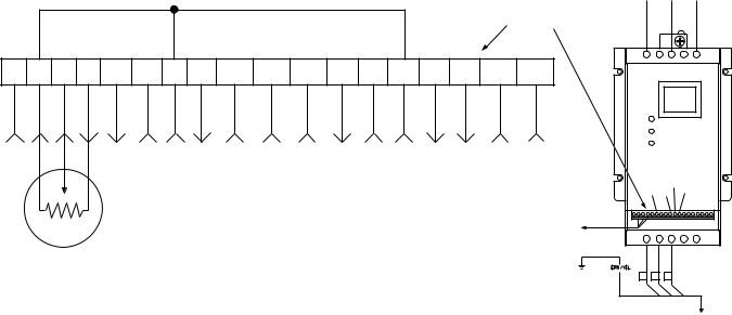
To operate these units at very low ambient temperatures, Motormaster V controls (Fig. 1) must be added. Field-fabricated and installed wind baffles are also required for units in areas with prevailing winds of more than 5 mph (8 kph) and where temperatures drop below 32 F (0° C). The Motormaster V control permits operation of the unit to an ambient temperature of –20 F (–29 C). The control regulates the speed of one or two 3-phase fan motors depending on unit size. Replacement of the fan motor on most units is not necessary since the control is compatible with the factory-installed fan motors. To verify that unit fan motors are compatible with the control see Table 1.
See Tables 2-4 for the Motormaster V control accessory package usage and contents. Field wiring of control is required.
Table 1 — Replacement Motor Part Numbers
48/50P2,P3,P4,P5 UNIT SIZE |
VOLTAGE |
ACCESSORY PART NUMBER |
|
|
208/230-3-60 |
Not Required, Std Unit Motor |
|
035 |
400-3-50, 460-3-60 |
Not Required, Std Unit Motor |
|
575-3-60 |
Not Required, Std Unit Motor |
||
|
|||
|
380-3-60 |
HD56AK380 |
|
|
208/230-3-60 |
HD52AK002 |
|
030, 040-060 |
400-3-50, 460-3-60 |
HD52AK002 |
|
575-3-60 |
Not Required, Std Unit Motor |
||
|
|||
|
380-3-60 |
Not Required, Std Unit Motor |
|
|
208/230-3-60 |
HD52AK002 (2 Required) |
|
070 |
400-3-50, 460-3-60 |
HD52AK002 (2 Required) |
|
575-3-60 |
Not Required, Std Unit Motor |
||
|
|||
|
380-3-60 |
Not Required, Std Unit Motor |
|
|
208/230-3-60 |
Not Available |
|
075-100 |
400-3-50, 460-3-60 |
HD52AK002 (2 Required) |
|
575-3-60 |
Not Required, Std Unit Motor |
||
|
|||
|
380-3-60 |
Not Available |
Manufacturer reserves the right to discontinue, or change at any time, specifications or designs without notice and without incurring obligations.
Catalog No. 04-53480070-01 |
Printed in U.S.A. |
Form 48/50P-2SI |
Pg 1 |
9-09 |
Replaces: New |
|
|
|
|
|
|
|
|
|
|
|
|
|
|
|
|
|
|
FROM FUSE BLOCK |
|||
|
|
|
|
|
|
|
|
|
|
|
|
|
|
|
|
TERMINAL |
BLK |
|
YEL |
BLU |
|
|
|
|
|
|
|
|
|
|
|
|
|
|
|
|
|
|
BLOCK |
|
|
|
|
1 |
2 |
5 |
6 |
1 |
12 |
2 |
14 |
13A |
13B |
13C |
15 |
25 |
2 |
30 |
31 |
TXA |
TXB |
L1 |
L2 |
L3 |
|
COM |
|
|
|
+5V |
|
|
|
|
|
|
|
|
|
|
|
|
|
|
|
|
B |
|
|
|
|
|
|
|
|
|
|
|
|
|
|
|
|
|
|
|
|
|
|
|
|
|
|
|
|
|
|
|
|
|
|
|
|
|
|
|
|
|
|
13B |
13C |
|
|
|
|
|
|
|
|
|
|
|
|
|
|
|
|
|
|
|
12 |
13A |
|
|
|
|
|
|
|
|
NOTE: Wire colors for MMPT: |
|
|
|
|
|
|
|
|
|
|||||
|
|
|
|
|
|
|
|
|
|
|
|
|
|
256 |
|
2 |
|
||||
|
|
|
|
|
|
|
2 — BLACK (A) |
|
|
|
|
|
|
|
|
|
|
||||
|
|
|
|
|
|
|
|
|
|
|
|
|
TO PRESSURE |
T1 T2 T3 B- B+ |
|||||||
|
|
|
|
|
|
|
5 — GREEN (C) |
|
|
|
|
|
|
||||||||
|
|
|
|
|
|
|
|
|
|
|
|
|
TRANSDUCER |
|
|
|
|
||||
|
|
|
|
|
|
|
6 — RED (B) |
|
|
|
|
|
|
|
|
|
|
|
|||
|
|
|
|
|
|
|
|
|
|
|
|
|
|
|
|
|
|
|
|
||
|
PRESSURE |
|
|
|
|
|
|
|
|
|
|
|
|
|
|
|
|
|
|
||
TRANSDUCER |
|
|
|
|
|
|
|
|
|
|
|
|
|
|
1 |
2 |
3 |
|
|||
|
|
|
|
|
|
|
|
|
|
|
|
|
|
|
|
|
|
|
|||
|
|
|
|
|
|
|
|
|
|
|
|
|
|
|
|
|
|
|
|
|
TO MOTOR(S) |
Fig. 1 — Motormaster® V Control
Table 2 — Motormaster® V Control Package Contents — 48/50P030-060 Units
ITEM |
CRLOWAMB033A00 |
CRLOWAMB034A00 |
CRLOWAMB035A00 |
Connector (1/2-in.) |
|
HW60EA001 |
|
Connector (1-in.) |
|
HW60HH006 |
|
Controller, 230 V 2 Hp |
HR46TN001 |
— |
— |
Controller, 460 V 2 Hp |
— |
HR46TN002 |
— |
Controller, 575 V 2 Hp |
— |
— |
HR46TN003 |
Enclosure |
|
30RA500381 |
|
Enclosure Cover |
|
30RA500519 |
|
Enclosure Mounting Bracket |
|
50EJ500656 |
|
Fan Relay |
|
HN61KK055 |
|
Relay Base |
|
HN79KK035 |
|
Fuse Block |
|
HY11UT035 |
|
Fuse 15A, KTK-R, Class CC |
— |
HY10KB151 (3) |
HY10KB151 (3) |
Fuse 20A, KTK-R, Class CC |
HY10KB200 (3) |
— |
— |
Harness Assembly |
|
48ZZ401971 |
|
Harness Assembly |
|
48EJ402454 |
|
Harness Assembly |
|
48ZZ402001 |
|
Label |
|
48ZZ502002 |
|
Transducer |
|
HK05ZZ001 |
|
Transducer Harness |
|
48EJ403240 |
|
Varnish Cloth (Large) |
|
48DA510141 |
|
Varnish Cloth (Small) |
|
38C24601 |
|
Wire Tie |
|
HY76TB123 (12) |
|
Wire Tie |
|
HY76TB045 (5) |
|
Wire, 16 Gage 72 in. Long |
|
WHT (1), GRY (1) |
|
2

Table 3 — Motormaster V Control Package Contents — 48/50P070-100 Units
ITEM |
CRLOWAMB036A00 |
CRLOWAMB037A00 |
CRLOWAMB038A00 |
Connector (1/2-in.) |
|
HW60EA001 (2) |
|
Connector (1-in.) |
|
HW60HH006 (2) |
|
Controller, 230 V 2 Hp |
HR46TN001 (2) |
— |
— |
Controller, 460 V 2 Hp |
— |
HR46TN002 (2) |
— |
Controller, 575 V 2 Hp |
— |
— |
HR46TN003 (2) |
Enclosure |
|
30RA500381 (2) |
|
Enclosure Cover |
|
30RA500519 (2) |
|
Enclosure Mounting Bracket |
|
50EJ500656 (2) |
|
Fan Relay |
|
HN61KK055 (2) |
|
Relay Base |
|
HN79KK035 (2) |
|
Fuse Block |
|
HY11UT035 (2) |
|
Fuse 15A, KTK-R, Class CC |
— |
HY10KB151 (6) |
HY10KB151 (6) |
Fuse 20A, KTK-R, Class CC |
HY10KB200 (6) |
— |
— |
Harness Assembly |
|
48ZZ401971 (2) |
|
Harness Assembly |
|
48EJ402454 (2) |
|
Harness Assembly |
|
48ZZ402001 (2) |
|
Label |
|
48ZZ502002 |
|
Transducer |
|
HK05ZZ001 (2) |
|
Transducer Harness |
|
48EJ403240 (2) |
|
Varnish Cloth (Large) |
|
48DA510141 (2) |
|
Varnish Cloth (Small) |
|
38C24601 (2) |
|
Wire Tie |
|
HY76TB123 (6) |
|
Wire Tie |
|
HY76TB045 (2) |
|
Wire, 16 Gage 72 in. Long |
|
WHT (2), GRY (2) |
|
Table 4 — Motormaster V Control Package Usage
UNIT |
VOLTAGE |
ITEM DESCRIPTION |
|
208/230 |
CRLOWAMB033A00 |
48/50P030-060 |
|
|
380, 400, 460 |
CRLOWAMB034A00 |
|
|
|
|
|
575 |
CRLOWAMB035A00 |
|
|
|
|
208/230 |
CRLOWAMB036A00 |
48/50P070-100 |
|
|
380, 400, 460 |
CRLOWAMB037A00 |
|
|
|
|
|
575 |
CRLOWAMB038A00 |
|
|
|
INSTALLATION
Pre-Installation — Inspect the contents of this accessory package before installing. File a claim with the shipper if there is shipping damage or if a part is missing.
Step 1 — Install Field-Fabricated Wind Baffles
 WARNING
To avoid the possibility of electrical shock, open all disconnects before installing or servicing this accessory.
On size 040-060 units, in areas with prevailing winds of more than 5 mph (8 kph) and where temperatures drop below 32 F (0° C), wind baffles must be field fabricated to ensure
proper cooling cycle operation at low-ambient temperatures with Motormaster V controls. Wind baffles are not needed on size 030, 035, and 070-100 units. See Fig. 2 for baffle details. Use 20-gage (1 mm) galvanized sheet metal, or similar corro- sion-resistant material for the baffles. Use field-supplied screws to attach baffles to unit. Screws should be 1/4-in. (6.3 mm) diameter or larger. Screws should not be more than 1/2-inch in length. Drill required screw holes for mounting baffles.
 CAUTION
To avoid damage to refrigerant coils, electrical components, and wiring use extreme care when drilling screw holes and screwing in fasteners.
3

WIND BAFFLE
a48-8561
BAFFLE INSTALLATION LOCATION (SIZES 050 AND 060 SHOWN)
a48-8560
|
|
|
|
|
|
|
|
|
|
|
|
|
|
|
|
|
|
|
|
|
|
|
|
|
|
|
|
|
|
|
|
UNIT SIZE |
QUANTITY |
DIMENSION “A” |
|
|
|
|
|
|
|
|
|
|
|
|
|
|
|
in. |
mm |
||
|
|
|
|
|
|
|
|
|
|
|
|
|
|
|
|
||
|
|
|
|
|
|
|
|
030,035 |
Not Used |
— |
— |
||||||
|
|
|
|
|
|
|
|
|
040-060 |
2 |
78.125 ± 0.125 |
1984 ± 3 |
|||||
|
|
|
|
|
|
|
|
070-100 |
Not Used |
— |
— |
||||||
|
|
|
|
|
|
|
|||||||||||
|
|
|
|
|
|
|
|
|
|
|
|
|
|
|
|
|
|
|
|
|
|
|
|
|
|
|
|
|
|
|
|
|
|
|
|
|
|
|
|
|
|
|
|
|
|
|
|
|
|
|
|
|
|
NOTE: 48/50P030, 035, and 070-100 units do not require baffles.
Fig. 2 — Wind Baffle Details
4
Step 2 — Mounting and Electrical Connections for Motormaster® V Control
 WARNING
To avoid possibility of electric shock and personal injury, open and tag all electrical disconnects before installing or servicing unit.
 WARNING
Hazard of electric shock. Wait three minutes after disconnecting incoming power before servicing drive. Capacitors retain charge after power is removed.
 CAUTION
To avoid damage to the small terminals on the Motormaster V control, use care when tightening the compression terminals and use the proper size screwdriver.
 CAUTION
DO NOT connect incoming AC power to Motormaster V output terminals T1, T2, and T3. Severe damage to the control will result.
48/50P030-060 UNITS — For 48/50P030-035 units, the Motormaster controlled outdoor-fan motor (OFM) is the no. 1 OFM (see Fig. 3). The no. 2 OFM is controlled by the Comfortlink head pressure control routine.
For 48/50P040 units, the Motormaster controlled outdoorfan motor (OFM) is the no. 3 OFM (see Fig. 3). The no. 1 and 2 OFMs are controlled by the Comfortlink head pressure control routine.
For 48/50P050-060 units, the Motormaster controlled out- door-fan motor (OFM) is the no. 1 OFM (see Fig. 3). The no. 2, 3, and 4 OFMs are controlled by the Comfortlink head pressure control routine.
Use the following procedure to mount and connect the MMV controllers to these units:
1.Disconnect power to the unit. Lockout and tag power disconnect.
2.Remove control box covers.
3.For size 030-035 units, remove panel from condenser section on OFM 1 side of the unit in order to gain access to the outdoor fan section. See Fig. 4. For size 040-060 units, remove panel above control box as shown in Fig. 5 and 6.
4.Mount accessory fuse block HY11UT035 and fan relay base HN79KK035 inside control box as shown in Fig. 7. Secure components with ½-in. sheet metal screws.
a.Insert fuses into fuse blocks and relays into relay bases.
b.Install harness 48EJ402454 from load side of CCB (control circuit breaker terminals 21, 22, 23) to line side of MMF (Motormaster V fuse block) as shown in Fig. 8. Note that it may be easier to pick up the load side of CCB from the ¼-in. male quick connect terminals on the line side (terminals 11, 12, 13) of the OFC contactors (see power schematic on control box door).
c.Connect FR (fan relay) coil to OFC1 coil using the 72-in. long 16 gage white and gray wires (stripped end goes to FR) as shown in Fig. 8.
5.Mount the MMV controller enclosure 30RA500381 on the bulkhead of the unit inside the outdoor fan section, as shown in Fig. 4-6, using the mounting brackets 50EJ500656 installed on the enclosure. Remove the enclosure cover and install the ½-in. HW60EA001 and 1-in. HW60HH006 connectors in the holes in the lower right hand side of the enclosure.
6.Connect transducer HK05ZZ001 to the liquid line service Schrader port of refrigerant Circuit A. Plug transducer cable 48EJ403240 into transducer. Run cable to the MMV enclosure, as shown in Fig. 4-6.
Run MMPT (Motormaster V pressure transducer) cable through ½-in. connector of MMV enclosure (do not tighten connector screws at this time). Connect red, green, and black wires to MMV terminals 6, 5, and 2 as shown in Fig. 8. Terminate drain wire of transducer cables under one of the lower MMV mounting screws.
7.Make remaining electrical connections to MMV (see Fig. 8).
a.In main control box, disconnect black, red, blue, and green wires from load side (terminals 21, 22, 23) of OFC1 (sizes 030-035, 050-060) contactor or
OFC 3 (size 040) (label cable from OFC1 or OFC3 (size 040) as OFM1 or OFM3 (size 040). Pull wires out through the hole in the bottom of the control box and run them up the corner post to the opening of the cable tray on the side of the control box, as shown in Fig. 4-6. Run the cable through the wire tray to the MMV enclosures.
b.Run the OFM1/OFC3 (040) cable through the 1-in. connector of the MMV enclosure (do not tighten connector screws at this time). Remove ring terminals from black, red, and blue wires and strip insulation back 3/8-in. Connect black, red, and blue wires to MMV terminals T1, T2, and T3. Connect green ground wire to MMV ground screw.
c.In the main control box connect Motormaster VFD (variable frequency drive) harness 48ZZ401971 to the load side of the MMF (label the opposite end of this harness as MMF). Run the harness along the bottom of the control box and out through the hole that the OFM harness was in. Pull the harness out through the hole in the bottom of the control box and run it through the opening of the cable tray (in the same manner as the OFM harnesses).
d.Run the MMF cable through 1-in. connector of the MMV enclosure (do not tighten connector screws at this time). Connect L1, L2, and L3 wires to MMV terminals L1, L2, and L3. Connect green ground wire to MMV ground screw. Place 1 large varnish cloth 48DA510141 around both cables at the point they enter the 1-in. connector. Tighten down connector screws being careful not to damage the cables.
e.In the main control box connect one Motormaster VFD harness 48ZZ402001 to the NO (normally open) contact of the FR (see Fig. 8). Run the harnesses along the bottom of the control box and out through the hole that the OFM harness was in. Pull the harness out through the hole in the bottom of the control box and run it through the opening of the cable (in the same manner as the OFM harness).
5
 Loading...