


37HS ModulineT Air Terminals
Application Data
|
CONTENTS |
|
Page |
INTRODUCTION . |
. . . . . . . . . . . . . . . . . . . . . . . . . . 1-2 |
BUILDING LOAD CALCULATION . . . . . . . . . . 2-23
Cooling . . . . . . . . . . . . . . . . . . . . . . . . . . . . . . . . . . . 2
· LOAD CONSIDERATIONS |
|
· DESIGN PROCEDURE |
|
Heating . . . . . . . . . . . . . . . . . . . . . . . . . . . . . . . . . . . |
20 |
· OVERHEAD AIR HEATING |
|
TERMINAL SELECTION AND LAYOUT . . . . . 23-41
Introduction . . . . . . . . . . . . . . . . . . . . . . . . . . . . . . . 23 De®nitions . . . . . . . . . . . . . . . . . . . . . . . . . . . . . . . . 23
Step 1 Ð Determine Air Volume (Cfm)
Per Terminal . . . . . . . . . . . . . . . . . . . . . . . . . . . . . 24
Step 2 Ð Lay Out Terminals . . . . . . . . . . . . . . . 25
Step 3 Ð Consider Unit Combinations
and Run-Out Duct . . . . . . . . . . . . . . . . . . . . . . . . 27
Step 4 Ð Determine Controller Location . . . . 37
Final Layout . . . . . . . . . . . . . . . . . . . . . . . . . . . . . . . 41
THE MODULINE VALVE . . . . . . . . . . . . . . . . . . . 41-44
The Moduline Control Concept . . . . . . . . . . . . . 41
·HIGH AND LOW PRESSURE
·BELLOWS PRESSURE
·UNIT AIRFLOW DELIVERY
CONTROL APPLICATIONS . . . . . . . . . . . . . . . . 44-50
Introduction . . . . . . . . . . . . . . . . . . . . . . . . . . . . . . . 44
System-Powered Controls . . . . . . . . . . . . . . . . . 44
·COMPONENTS OF THE SYSTEMPOWERED CONTROL SYSTEM
·SYSTEM-POWERED APPLICATIONS Constant Volume (CV) Cooling
CV Heating
Variable Air Volume (VAV) Cooling VAV Cooling With Warm-Up
VAV Heating and Cooling With Changeover VAV Heating
·SYSTEM-POWERED CONTROLS WITH
ELECTRIC INTERFACE
VAV Cooling With Electric Warm-Up
VAV Heating and Cooling With Electric Changeover
VAV Cooling With Electric Heat Interlock
·SYSTEM-POWERED CONTROLS WITH PNEUMATIC INTERFACE
Pneumatic Sequenced Cooling/Heating (Hot Water)
VAV Cooling With Pneumatic Warm-Up
VAV Cooling With Fire Safety
Night Set Back Heating
VAV Cooling/Separate System Heating
CONTROL SELECTION . . . . . . . . . . . . . . . . . . . 50-54
Control Index . . . . . . . . . . . . . . . . . . . . . . . . . . . . . 50
Control Packages . . . . . . . . . . . . . . . . . . . . . . . . . 50
CONTROL OPERATING SEQUENCES . . . . . . 55-71
System-Powered Controls . . . . . . . . . . . . . . . . . 55
·CV COOLING
·CV HEATING
·VAV COOLING
·VAV COOLING WITH WARM-UP
Page
·VAV HEATING AND COOLING WITH SYSTEM-POWERED CHANGEOVER
·VAV HEATING
System-Powered Controls With
Electric Interface . . . . . . . . . . . . . . . . . . . . . . . . . 64
·VAV COOLING WITH ELECTRIC WARM-UP
·VAV HEATING AND COOLING WITH ELECTRIC CHANGEOVER
·VAV COOLING WITH ELECTRIC HEAT
INTERLOCK
System-Powered Controls With
Pneumatic Interface . . . . . . . . . . . . . . . . . . . . . . 69
·PNEUMATIC SEQUENCED HEATING/ COOLING (HOT WATER)
·VAV COOLING WITH PNEUMATIC WARM-UP OR FIRE SAFETY SWITCH
AIRFLOW ADJUSTMENT . . . . . . . . . . . . . . . . . . |
71,72 |
Maximum Air¯ow (Cfm) Adjustment . . . . . . . |
. 71 |
Minimum Air¯ow (Cfm) Adjustment . . . . . . . . . |
71 |
Variation in Maximum Air¯ow . . . . . . . . . . . . . . |
72 |
AIR DISTRIBUTION . . . . . . . . . . . . . . . . . . . . . . . . 73
Throw for Standard Diffusers . . . . . . . . . . . . . . . 82
INTRODUCTION
The Modulinet air terminal (Fig. 1) is a truly ¯exible unit for the control and distribution of conditioned air to the occupied space. Available in 3 air¯ow sizes for single or multiple terminal installation, it is adaptable to a variety of
Fig. 1 Ð Moduline Air Terminal
Manufacturer reserves the right to discontinue, or change at any time, speci®cations or designs without notice and without incurring obligations.
Book |
3 |
|
PC 201 |
Catalog No. 513-741 |
Printed in U.S.A. |
Form 37HS-1XA |
Pg 1 |
6-91 |
Replaces: New |
Tab |
6a |
|
|
|
|
|
|
|
|
|
|
|
|
|
|
|
|
|
|
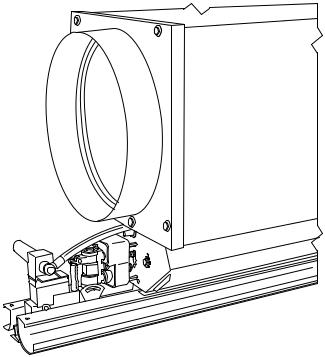
ceiling designs and building control systems. Modulinet terminals installed in modular ceilings can be moved easily when tenant requirements change, and the quiet, linear slot distribution integrates well in most commercial ceilings. Figure 2 shows a 37HS Moduline unit with variable air volume (VAV) controls.
The basic Moduline terminal control system is system powered; the distribution duct pressure provides the energy to operate the devices that control all the units in the system. This system can be thought of as reactive. The control reacts to changes in occupied space conditions and to changes in supply duct air¯ow and pressure, and adjusts the unit valve to maintain preset air¯ow or ¯ow proportional to the room load.
It is also possible to apply directive controls, both pneumatic and electric, to the Moduline terminal. In these applications, the Moduline control system is still system powered. The difference is that now the space can be controlled by other sensors and devices, replacing the reactive control devices.
This application data book provides design guidance for layout of a Moduline system. All aspects of the unit application are included: Unit layout, control location, control
Fig. 2 Ð 37HS Unit With VAV Controls
characteristics, control system options and air distribution characteristics. This book covers both system-powered control and system-powered with electric or pneumatic interface controls. Application information for Carrier's electronic Product Integrated Controls (PIC) can be found in a separate publication. (Moduline units with PIC controls can be controlled as part of the Carrier Comfort Network [CCN] system.) Sound power levels and sound application data are found in the 37HS Sound Application Data book. Speci®c mounting and installation data is found in the 37HS Installation, Start-Up and Service instructions or, for PIC units, in the 37HC Installation, Start-Up and Service Instructions.
BUILDING LOAD CALCULATION
Cooling Ð In order to select Moduline equipment and lay out the building air distribution system, it is ®rst necessary to calculate the building cooling and heating loads which the Moduline terminals will offset.
The ®rst step is to determine the complete ``block'' load for the building in order to size the fan, cooling equipment and trunk duct. This estimate is for the month and hour of greatest total building load. (See Fig. 3.)
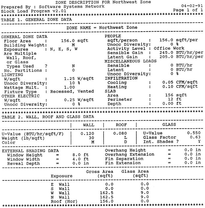
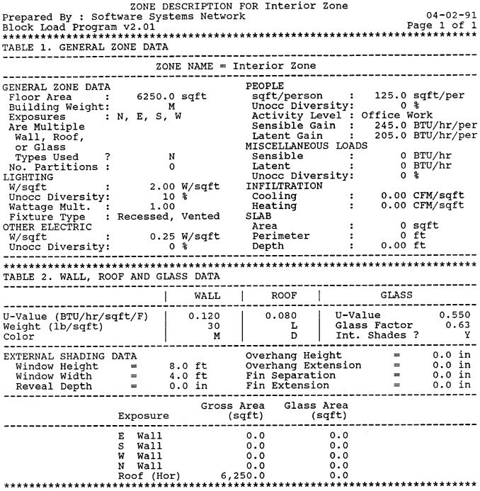
The next step is to estimate each zone load (sensible heat only). These are used to size the terminals and run-out ducts. The zone peak load estimates are for different months and hours, depending on zone window orientation. (See Fig. 4.)
These calculations are made for a building which will utilize Moduline units in both perimeter and interior spaces. The Moduline system supplies all building cooling. The heating system is described on page 20.
The object of making these load estimates is to arrive at the required air volumes, so that the system can be designed and equipment selected.
The air¯ow through a variable volume system is constantly changing in response to the changes in the building cooling loads. At any one moment the air¯ow to each temperature control zone is determined by the room sensible heat cooling load (RSH), the supply air temperature (T SA ) and the room thermostat setting (TR ), as shown in the following equation:
Zone cfm = |
RSH |
|
|||
1.09* (T |
R |
− T |
) |
||
|
|||||
|
|
|
SA |
||
*1.09 is constant in this formula.
The fan air¯ow at the same moment is the sum of all the zone air¯ow rates. (Duct leakage is assumed to be negligible because of the high quality duct construction required by VAV systems.)
2
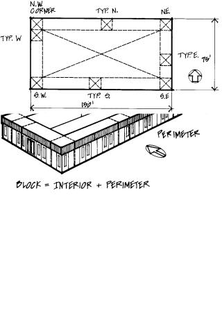
Fig. 3 Ð Estimating Block Load
Fig. 4 Ð Floor Plan of Typical Zones for Single-Story Office Building
LOAD CONSIDERATIONS
Lighting Ð Even though lighting loads (Watts/sq ft) are considerably lower in today's buildings, the lighting is by far the largest load component.
It is necessary, therefore, to pay close attention to getting an accurate estimate of the lighting requirements.
In estimating the lighting load, special consideration should be given to evaluating storage effect and the performance of return air ceiling plenums. Both of these items reduce the peak room load from lights and delay the time at which the stored heat becomes a load on the central equipment.
Oversizing Ð Oversizing of variable volume systems results in unused equipment capacity and worse performance at part load, not in increased system air¯ow. The actual system operation will re¯ect the actual system load, not the design load. If conservative data, safety factors, or provision for future loads are included in the design estimate, the actual system air¯ow will not be increased. The equipment will be capable of handling an increased load should it ever exist, but will automatically throttle back to handle only the actual load at that moment.
It is recommended that safety factors not be included in load calculations; they are not included in the following method.
Air Motion, Ventilation and Odor Dilution Ð Air motion, ventilation, and odor dilution deserve special attention in the design of a VAV system. The designer must visualize the correct system operating condition in order to evaluate the adequacy of these items at either full or part-load cooling conditions, or during the heating season.
Room air motion is determined by the supply air quantity and the diffuser induction ratio. The minimum room air velocity is higher if building humidity and temperature are higher. The design cfm at peak cooling load in any zone should be not less than the minimum shown below:
DESIRED |
DESIGN CFM |
ROOM TEMPERATURE |
AT PEAK COOLING |
(F) |
(cfm/sq ft) |
78 |
0.7 |
75 |
0.4 |
These minimums are based on using the Carrier Moduline diffuser, which has very high performance; competitive diffusers require a higher cfm/sq ft.
The outside air cfm requirement at maximum design conditions may be determined by local building code. If the outside air cfm to the central air handler is adequate to maintain a low overall building odor level, the odor level in a particular space will depend upon the odors generated locally in that space and the supply air¯ow to that space. A space with high odor generation (a conference room with much smoking) should be provided with a separate exhaust system to increase the air ¯ow through the space for odor dilution. The only way to increase the VAV air¯ow to that space would be to add reheat to increase the room sensible heat, which is unacceptable from an energy conservation standpoint.
The following odor dilution cfm (either VAV supply or supplemental exhaust cfm) is usually adequate:
Private or General Office Ð 0.25 cfm/sq ft Major Conference Room Ð 1.0 cfm/sq ft
3
Supply Air Temperature Ð In systems using draw-thru air handling units and high induction Carrier Modulinet terminal units, the acceptable range of supply air temperatures at the terminals is from 50 to 54 F. The cooling coil ADP (Apparatus Dew Point) will be from 3 to 5° F lower than the supply air temperature, due to allowance for coil bypass, fan heat and duct gain.
The system installed cost for ductwork, central air handler, and VAV terminals will be greater if the air quantity is higher because of the designer's choice of a higher supply air temperature. The increased fan air quantity will result in higher fan operating cost, which may be offset by the lower cost of operating the refrigeration system at a higher suction temperature. The higher coil surface temperature (ADP) of the system will result in a higher building humidity, which will be less comfortable and require greater ventilation air.
An unduly low choice of supply air temperature may result in unacceptably low room air motion in interior zones with low lighting levels, and in unnecessarily low humidity.
The same supply air temperature must be used for the zone load and block load estimates.
Load Calculating Methods Ð The cooling load estimates can be made very accurately and quickly using the Carrier E20-II Block Load program.
Because of the computer's speed, it is not necessary to compromise the design procedure to obtain the most accurate result. The optimum design procedure listed here assumes the use of the E20-II program, and may require ``short cuts'' when using manual methods.
While the E-20 program is the most convenient and rapid method of load calculation, other methods will also provide the required results. In particular, Carrier multi-room load estimating form E-5056 is available for this purpose.
DESIGN PROCEDURE (with example)
Data Collection Ð Our example uses Cincinnati, Ohio as a representative city. The building is a one-story office building with 11,250 sq ft. The building layout is shown in Fig. 4 on page 3.
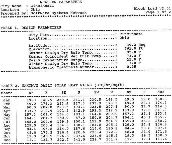
1.Using the E20-II Block Load Program, select Cincinnati for its weather data. The WEATHER PARAMETERS printout shown on pages 5 and 6 shows the weather data used for the load estimating calculations.
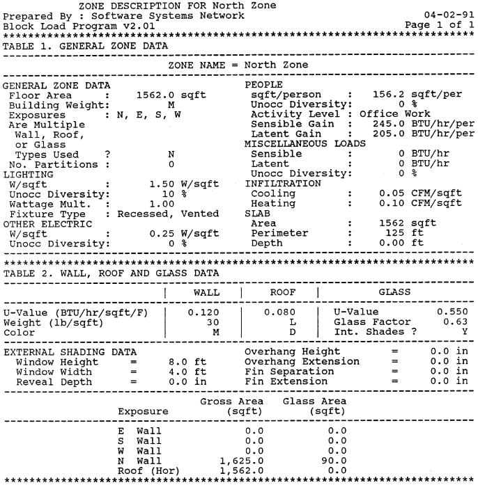
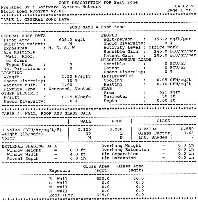
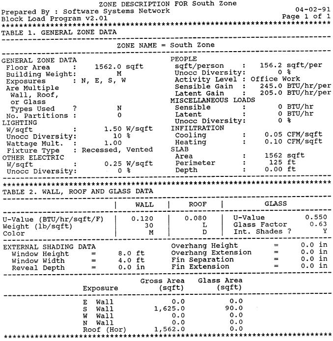
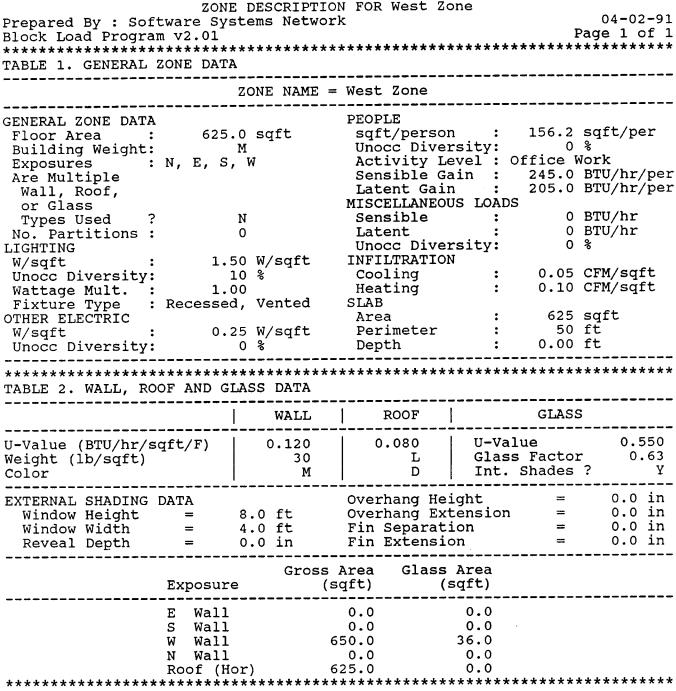
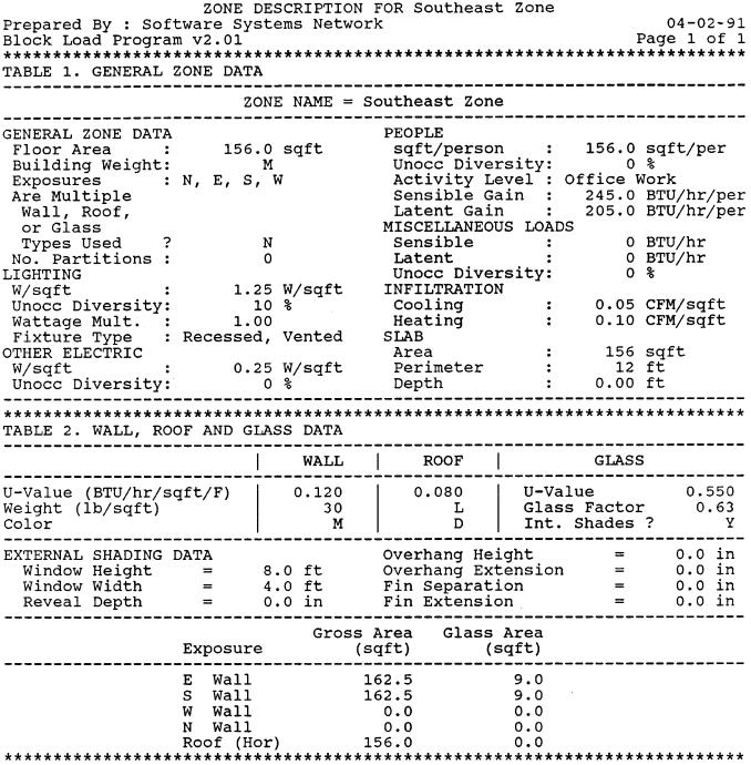
2.The next step is to gather data on the building, including dimensions, construction materials used, internal load patterns (such as lighting levels) and the building orientation. For our example, we have divided the building into nine zones. The actual building has ten zones on its north exposure, but we've grouped them all into a single zone because zones on the same exposure tend to have similar load patterns. Similarly, the ten south exposure zones have been grouped into a single zone, and the four east and west zones have been combined into single east and west zones respectively.
Pages 7-15 contain the ZONE DESCRIPTION printouts for each of the nine zones.
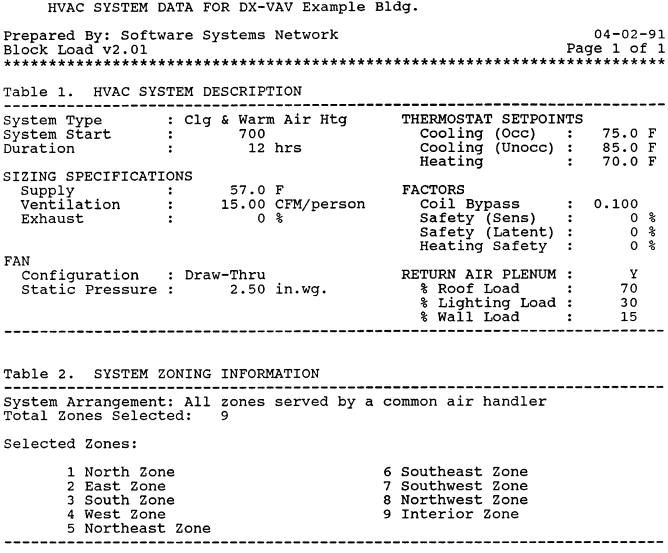
3.The ®nal input step is to select an initial set of system design data, including the cooling and heating set points, the supply air temperature (or supply air¯ow rate, if that is known) and the fan static pressure. This system design data will, of course, be directly in¯uenced by the actual central station equipment, be it packaged or applied.
Page 16 shows the HVAC SYSTEM DATA printout which lists the system design data we've selected for this example.
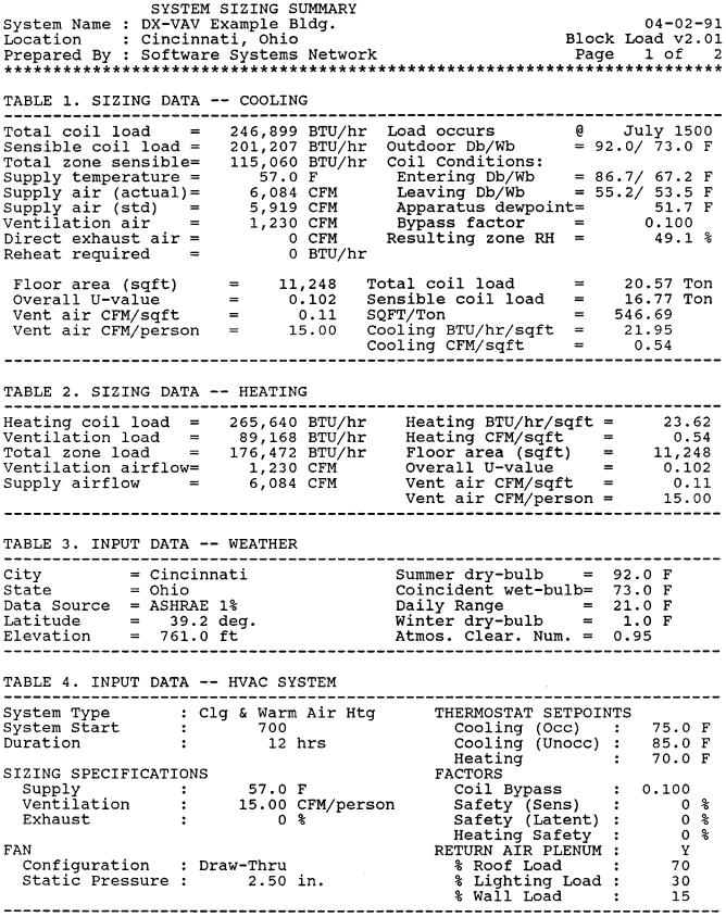
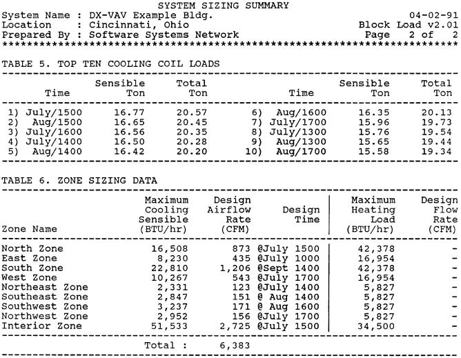
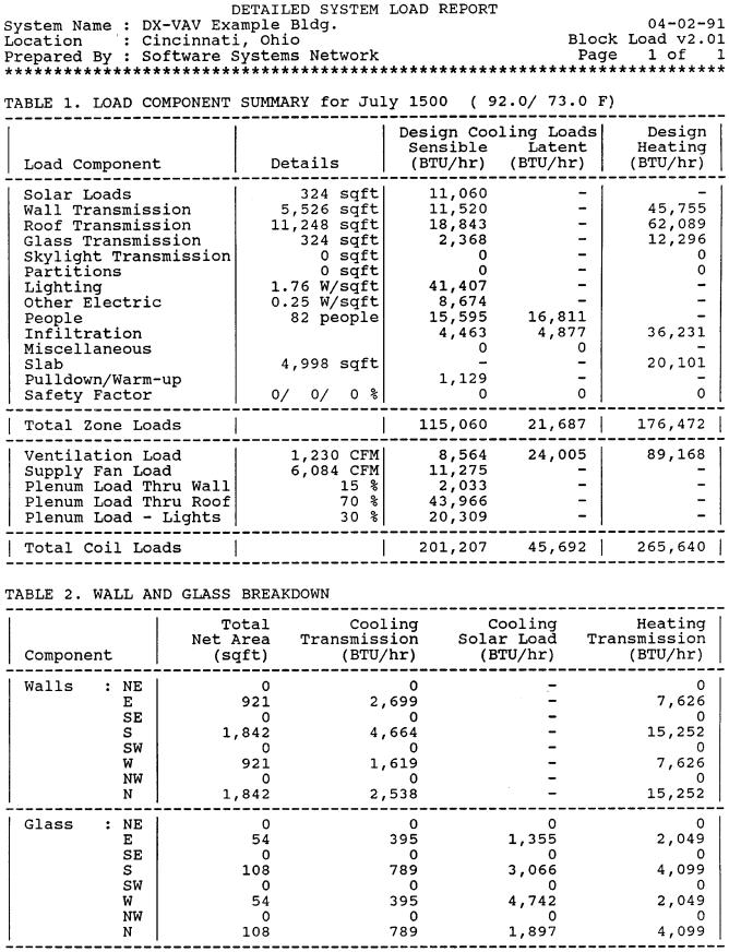
Load Calculations Ð With the input data from Step 1, the Block Load Program calculates the building loads for each month of the year to ®nd the largest load on the building's air conditioning system. Typically, this will occur during the middle or late afternoon hours in July or August. The SYSTEM SIZING SUMMARY printout shown on pages 17 and 18 provides both the cooling and heating equipment sizing data. At the same time, it provides the maximum cooling load, maximum heating load and design air¯ow rate for each zone in the building. Notice that each zone may peak at a month and hour different from that at which the HVAC system peaks. The detailed system load report is shown on page 19.
4
5

6
7
8
9
10
11
12

13
14
15
16
17
18
19
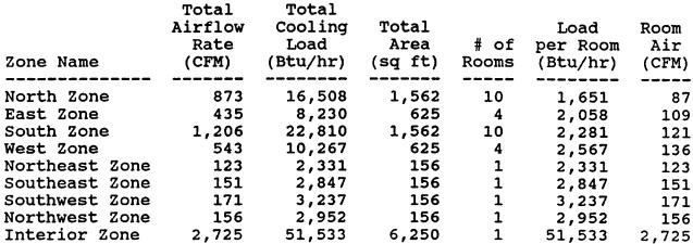
Modulinet Selection (Analysis of Data) Ð The printout shown below presents an analysis of the preceding data.
Heating Ð Heat must be provided in a building to offset losses through the perimeter walls, windows, and roof. In the interior spaces the heat gain from lights and people will in many cases be enough to cause a cooling load even in winter.
The two most commonly used heating systems are these:
·Baseboard
·Overhead air
Baseboard has been used historically in the North because it is effective in overcoming the downdraft from windows, particularly with the large single pane windows used in the past.
Now, with improvements in the building thermal envelope due to better materials and construction methods, overhead air heating is a viable and attractive alternative.
Overhead air heating, when properly applied, can handle all requirements except the severe cases in which the wall U values and temperature differences are large.
Overhead air heating is the method which will be considered for these procedures.
OVERHEAD AIR HEATING Ð Two basic forms of overhead heating are used with Moduline cooling systems:
·Separate duct heating
·Changeover Moduline heating/cooling
Separate Duct Heating Ð A simple type of overhead air heating system for use with a Moduline cooling system consists of a series of ceiling outlets, placed around the perimeter of the building close to the outside wall, which blow warm air outward and/or downward to ¯oor level. The outlets are connected by a simple duct system to an electric (or hot water) heating-only fan coil unit located above the ceiling. (See Fig. 5.) A minimum of one fan coil unit per exposure is used for each story of the building. The fan coil unit draws air from the ceiling plenum and distributes it to the building perimeter by means of a separate duct system. This type of heating system operates at constant volume.
The separate duct heating approach allows heat to blanket the outside wall, eliminating the transmission of heat through the outside wall and permits the Moduline cooling units to be located in the best arrangement for cooling distribution. Control interlock between separate system heating and Moduline cooling is outlined in the Control Applications section, on page 44.
The 35BD heating slot boot diffuser (Fig. 6) is speci®- cally designed for this heating approach and will provide excellent distribution of the hot air necessary to offset the load.
20
Fig. 5 Ð Separate Duct Heating System
Performance Heating Ð Downblow Slot
NOMINAL |
|
2 |
|
|
4 |
|
|
LENGTH (ft) |
|
|
|
|
|||
|
|
|
|
|
|
||
TYPE |
|
Placement |
|
Placement |
|||
Cfm |
(in.) |
Cfm |
(in.) |
||||
DIFFUSER |
|
|
|
|
|
|
|
|
Min |
Max |
|
Min |
Max |
||
|
|
|
|||||
Heating Slot |
20-70 |
12 |
24 |
25-120 |
12 |
24 |
|
Boot Diffuser |
|||||||
|
|
|
|
|
|
||
NOTES:
1.Minimum and maximum show distance diffuser should be located from perimeter wall in inches.
2.For optimum performance of the diffuser, the air temperature should be held between 90 and 115 F.
Fig. 6 Ð 35BD Heating Slot Boot Diffuser
21
Changeover Modulinet Heating/Cooling Ð Both hot air and cold air distribution are possible with a Moduline system. The Moduline unit uses a director diffuser which, sensing the duct temperature of the supply air, directs the air towards or away from the perimeter wall. (Fig. 7.)
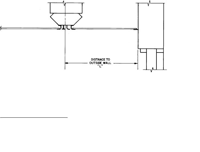
The Moduline location for heating and cooling requires the unit to be a speci®c distance from the outside wall in order to produce satisfactory distribution of the hot air. The recommended location is shown in Fig. 8.
HEATING |
COOLING |
With hot air in the duct, all discharge air is directed towards the perimeter wall to offset the transmission.
With cold air in the duct, the discharge is two-way blow Ð both into the room and towards the wall.
Fig. 7 Ð Director Diffuser
DISTANCE TO OUTSIDE WALL ``L''
Minimum |
|
Maximum |
|
|
L = |
M − H |
|
|
2 |
|
|
|
|
|
|
|
Where: |
||
2.5 Ft |
M = Max Throw |
||
|
|
for Heating |
|
|
|
One-Way Blow |
|
|
H = |
Ceiling Height |
|
|
|
|
|
Fig. 8 Ð Recommended Location for Changeover ModulineT Heating/Cooling
22
Additional Guidelines for Heating Ð In addition to downblow slot boot diffusers and Moduline director diffusers, round nozzles spaced along the perimeter wall will also provide satisfactory overhead heating distribution. Some guidance for outlet use are shown in Tables 1 and 2.
Moduline heating and cooling is less ¯exible than separate duct system heating with Moduline cooling because:
·Moduline heating/cooling is a changeover system requiring complete replacement of the cooling duct supply air with heated air, making zone control difficult.
·Moduline location is a compromise between obtaining outside wall coverage with hot air and good cooling distribution.
Thus, separate duct heating can provide heat for a given exposure without materially affecting the building cooling system. The heating outlets and Moduline terminals can be located in the most efficient air distribution places of the conditioned space.
Table 1 Ð Optimum Outlet Discharge
DIFFUSER SLOTS |
VELOCITY (Fpm) |
TEMPERATURE (F) |
Downblow slots |
500 to 1250 |
90 to 115 |
Round nozzles |
900 to 1800 |
90 to 125 |
One-way blow slots |
600 to 2200 |
80 to 105 |
Director Diffusers |
800 to 2200 |
90 to 105 |
Table 2 Ð Location Guidelines
DIFFUSER STYLE |
MINIMUM |
MAXIMUM |
|
DISTANCE (ft)* |
DISTANCE (ft)* |
||
|
|||
Round Nozzles and |
1.0 |
2.0 |
|
Downblow Slots |
|||
|
|
||
One-Way Blow Slots |
0.5 |
L² |
|
Director Diffusers |
2.5 |
L² |
*Feet away from outside wall. ²See Fig. 8.
TERMINAL SELECTION
AND LAYOUT
Introduction Ð Selecting the terminals and making a layout is one of the most important steps in the design process. This is where you use your knowledge to lay out the job at a low cost and still give your client a satisfactory job.
There are 4 items which must be considered when selecting an air terminal:
·air volume (Cfm) per terminal Ð a function of 1) the desired sound level in the space, and 2) cost
·layout Ð a function of 1) the proper room air motion and
2)physical spacing
·unit combinations and run-out duct
·controller location
De®nitions Ð Following are de®nitions of terms used when discussing the layout of a Moduline system.
Moduline units are arranged as single units or as units in an air series.
SINGLE UNIT Ð A single unit is connected to the supply duct and supplies conditioned air to a space or part of a space. Fig. 9.
AIR SERIES Ð Units in air series are connected unit-to- unit or with interconnecting ductwork and the supply air for all units enters the ®rst unit in the series. Fig. 10.
MASTER UNIT Ð A Moduline unit with controller, alone or in air series, is a master unit. Fig. 11.
SLAVE UNIT Ð A unit in air series, controlled by another unit (master unit) is a slave unit. Fig. 11.
CONTROLS Ð System-powered controls are installed at the jobsite and consist of the components shown below:
Constant Volume Ð Filter and volume controller.
Variable Volume, Diffuser Thermostat Ð Filter, volume controller, thermostat with aspirator.
Variable Volume, Wall Thermostat Ð Filter, volume controller, wall thermostat.
23
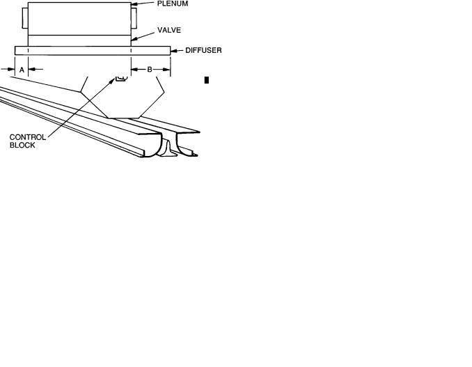
Fig. 9 Ð Single ModulineT Unit Connected to
Supply Duct
Fig. 10 Ð Moduline Units in Air Series
Fig. 11 Ð Master Unit and Slave Units
CONTROL END Ð The control end of a Modulinet unit is the end containing a control block at the end plate of the valve section of the unit. (Fig. 12.) The end of the unit opposite the control end contains a blank block. The control end of the Moduline unit is at the longer of the diffuser projections from the plenum. In Fig. 13, the longer projection, B, is the control end.
The ®lter, volume controller, and diffuser-mounted thermostat are applied to the control end of a master unit.
Fig. 12 Ð Control Block
Fig. 13 Ð Control End of Unit
Step 1 Ð Determine Air Volume (Cfm) Per Terminal Ð Before you can start making a layout, you must know the required air volumes (cfm).
Use the cfm per zone you obtained from the cooling load calculation and, using Table 3, Recommended Maximum Cfm Per Terminal, decide on the number of terminals you will need in each zone.
Cost dictates that the fewest number of Moduline units be used consistent with good design. The maximum cfm per unit that can be used (to keep the total number of units down) is mainly a function of maximum acceptable sound level.
Perimeter zones with glass in the east, west, and south building zones have peaks of rather short duration (i.e. loads vary widely during the course of the day and year). Therefore, a higher sound level can be tolerated for these short peaks.
24
As a result, slightly higher maximum cfm per unit is allowed as compared to interior zones or the north perimeter, which have relatively constant loads.
The maximum cfm per unit also is affected by the desired sound level in the room and the type of use of the space.
For example, an executive office uses low sound levels but the furnishings generally absorb more sound so the allowable cfm/unit is only slightly lower than other types of rooms.
Table 3 Ð Recommended Maximum Cfm
Per Terminal
|
|
|
|
MODULINE UNITS |
|
|
||
TYPE OF |
37HS1 |
37HS2 |
|
37HS4 |
||||
East |
Interior |
East |
Interior |
|
East |
Interior |
||
SPACE USE |
|
|||||||
West |
West |
|
West |
|||||
|
|
and |
and |
|
and |
|||
|
|
and |
and |
|
and |
|||
|
|
North |
North |
|
North |
|||
|
|
South |
South |
|
South |
|||
|
|
|
|
|
|
|||
General |
|
110 |
95 |
220 |
190 |
|
400 |
350 |
Office |
|
|
||||||
|
|
|
|
|
|
|
|
|
|
With |
100 |
90 |
200 |
180 |
|
330 |
300 |
Private |
Carpet |
|
||||||
|
|
|
|
|
|
|
||
Office |
With |
90 |
80 |
180 |
160 |
|
300 |
270 |
|
Tile |
|
||||||
|
|
|
|
|
|
|
|
|
Executive |
85 |
75 |
170 |
150 |
|
280 |
250 |
|
Office |
|
|
||||||
|
|
|
|
|
|
|
|
|
Step 2 Ð Lay Out Terminals
LOCATE UNITS IN T-BAR GRID Ð In making a layout, begin with a plan view of the ceiling. Normally, the ceiling grid and the lighting is done ®rst and the diffuser plan must ®t the layout.
The center of the room is the ideal location, but where that space has been reserved for lighting, the Moduline diffuser has enough ¯exibility to provide good distribution when not centered in the room.
For a two-way blow diffuser, anywhere from the 1¤4 point to the 1¤4 point (wall to wall) is usually suitable. Outside of the 1¤4 points, a one-way blow diffuser may be needed. Use two-way blow diffuser wherever possible and one-way blow only when really necessary. (See Fig. 14.)
Fig. 14 Ð Diffuser Locations for
Preferred 2-Way or One-Way Blow
Most jobs use a 2- x 4-ft grid T-Bar ceiling with 2- x 4-ft or 2- x 2 ft tiles.
The ®rst consideration in making a layout is to place the terminals as economically as possible in the grid, which means locating the terminals perpendicular to the main tees.
Main tees (the ones with hangers) are 4 ft on center (normally) and the cross tees are spaced 2 ft apart between the mains to make up a 2- x 4-ft T-bar grid. Additional trim tees may be used to divide the ceiling into a 2- x 2-ft grid.
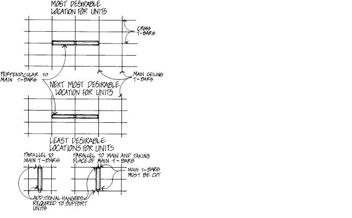
The Moduline units use mounting brackets and hang from (run perpendicular to) the main tees. While the units can be installed anywhere between mains, the most common location is on the center line of the cross tee (replaces the cross tee). The next most common location is half way between cross tees. See Fig. 15.
While less desirable, the units can be run parallel to the main tees. Unless absolutely necessary the units should not replace the main tee because this means the main tee must be cut. A location halfway between the mains is common and in this case additional hangers are required to the upper plenum of the unit or to the cross tee near the unit.
Special units are available for many other types of ceilings.
Fig. 15 Ð Terminal Location
25
EVALUATE THE THROW OF MODULINEt UNITS IN POSSIBLE LOCATIONS Ð Check minimum throw for 2-way blow diffuser near walls and all one-way blow diffusers.
Exceeding maximum throw is almost never a problem. A 2-way blow unit covers 50 ft at nominal cfm.
In perimeter rooms, if 2-way blow units are off center, favor the exterior wall if possible.
Generally, one-way blow diffusers should blow away from the nearest wall.
Air throw data in Tables 4 and 5 for the Modulinet air terminals provides the suggested minimum and maximum coverages the units can handle in a typical installation while maintaining the desired room conditions.
The optimum air throw values given in the table are distances from the unit centerline to the outside wall or nearest obstruction (wall, light ®xture, or opposing air stream).
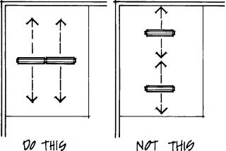
When given a choice, always put diffusers in line with each other, not blowing at each other. If diffusers must be placed so they are blowing at each other, the minimum throw must be checked. Do not put units closer together than minimum allows. Down-drafts caused by going below minimum will bother room occupants. (Fig. 16)
Modulinet units can be placed fairly close to a wall or partition. This is because the down-draft follows the wall (stays close to the wall) and doesn't bother the room occupant. If furniture is placed against the wall near a Moduline unit, it causes the air to be de¯ected causing drafts. The problem can often be solved by moving the furniture 6 in. or so away from the wall.
Fig. 16 Ð Locate Units to Prevent Down-Drafts
Table 4 Ð Air Throw Data Ð
1-Way and 2-Way Blow, 2-Slot Diffusers
37HS1 UNIT |
|
OPTIMUM AIR THROW (ft) |
|
||
|
|
|
|
|
|
AIRFLOW |
1-Way Blow |
2-Way Blow |
|||
(Cfm) |
|
|
|
|
|
Min |
Max |
Min |
|
Max |
|
|
|
||||
40 |
2.0 |
7.0 |
2.0 |
|
5.0 |
50 |
4.0 |
9.0 |
3.0 |
|
6.0 |
60 |
7.5 |
12.0 |
3.5 |
|
7.5 |
70 |
8.0 |
15.0 |
4.0 |
|
9.0 |
80 |
9.0 |
18.0 |
4.5 |
|
10.5 |
90 |
10.0 |
20.0 |
5.0 |
|
11.5 |
100 |
11.0 |
22.0 |
6.0 |
|
13.0 |
110 |
12.0 |
24.0 |
7.0 |
|
15.0 |
|
|
|
|
|
|
37HS2 UNIT |
|
OPTIMUM AIR THROW (ft) |
|
||
|
|
|
|
|
|
AIRFLOW |
1-Way Blow |
2-Way Blow |
|||
(Cfm) |
|
|
|
|
|
Min |
Max |
Min |
|
Max |
|
|
|
||||
|
|
|
|
|
|
80 |
2.0 |
7.0 |
2.0 |
|
5.0 |
100 |
4.0 |
9.0 |
3.0 |
|
6.0 |
120 |
7.5 |
12.0 |
3.5 |
|
7.5 |
140 |
8.0 |
15.0 |
4.0 |
|
9.0 |
160 |
9.0 |
18.0 |
4.5 |
|
10.5 |
180 |
10.0 |
20.0 |
5.0 |
|
11.5 |
200 |
11.0 |
22.0 |
6.0 |
|
13.0 |
220 |
12.0 |
24.0 |
7.0 |
|
15.0 |
|
|
|
|
|
|
37HS4 UNIT |
|
OPTIMUM AIR THROW (ft) |
|
||
|
|
|
|
|
|
AIRFLOW |
1-Way Blow |
2-Way Blow |
|||
(Cfm) |
|
|
|
|
|
Min |
Max |
Min |
|
Max |
|
|
|
||||
160 |
8.5 |
16.0 |
5.0 |
|
7.0 |
200 |
10.0 |
20.0 |
6.0 |
|
10.0 |
250 |
11.0 |
21.0 |
7.0 |
|
13.0 |
300 |
12.0 |
22.0 |
8.0 |
|
17.0 |
350 |
14.0 |
23.0 |
9.0 |
|
19.0 |
400 |
15.0 |
25.0 |
10.0 |
|
21.0 |
440 |
17.0 |
29.0 |
13.0 |
|
24.0 |
Table 5 Ð Air Throw Data Ð
2-Way and 1-Way Director, 3-Slot Diffusers
37HS1 UNIT |
|
|
OPTIMUM AIR THROW (ft) |
|
||||
|
|
|
|
|
|
|
||
|
Heating |
Cooling |
|
|||||
AIRFLOW |
|
|
|
|
|
|
|
|
1-Way Blow |
2-Way Blow |
|||||||
(Cfm) |
||||||||
|
Min |
|
|
Max |
Min |
|
Max |
|
40 |
2.0 |
|
7.0 |
2.0 |
|
5.0 |
||
50 |
4.0 |
|
9.0 |
3.0 |
|
6.0 |
||
60 |
7.5 |
|
12.0 |
3.5 |
|
7.5 |
||
70 |
8.0 |
|
15.0 |
4.0 |
|
9.0 |
||
80 |
9.0 |
|
18.0 |
4.5 |
|
10.5 |
||
90 |
10.0 |
|
20.0 |
5.0 |
|
11.5 |
||
100 |
11.0 |
|
22.0 |
6.0 |
|
13.0 |
||
110 |
12.0 |
|
24.0 |
7.0 |
|
15.0 |
||
|
|
|
|
|
|
|
||
37HS2 UNIT |
|
|
OPTIMUM AIR THROW (ft) |
|
||||
|
|
|
|
|
|
|||
|
Heating |
Cooling |
|
|||||
AIRFLOW |
|
|
|
|
|
|
|
|
1-Way Blow |
2-Way Blow |
|||||||
(Cfm) |
||||||||
|
Min |
|
|
Max |
Min |
|
Max |
|
80 |
2.0 |
|
7.0 |
2.0 |
|
5.0 |
||
100 |
4.0 |
|
9.0 |
3.0 |
|
6.0 |
||
120 |
7.5 |
|
12.0 |
3.5 |
|
7.5 |
||
140 |
8.0 |
|
15.0 |
4.0 |
|
9.0 |
||
160 |
9.0 |
|
18.0 |
4.5 |
|
10.5 |
||
180 |
10.0 |
|
20.0 |
5.0 |
|
11.5 |
||
200 |
11.0 |
|
22.0 |
6.0 |
|
13.0 |
||
220 |
12.0 |
|
24.0 |
7.0 |
|
15.0 |
||
|
|
|
|
|
|
|||
37HS4 UNIT |
|
|
OPTIMUM AIR THROW (ft) |
|
||||
|
|
|
|
|
||||
|
Heating |
Cooling |
|
|||||
AIRFLOW |
|
|
|
|
|
|
|
|
(Cfm) |
1-Way Blow |
2-Way Blow |
||||||
|
Min |
|
|
Max |
Min |
|
Max |
|
|
|
|
|
|
|
|
||
160 |
8.5 |
|
16.0 |
5.0 |
|
7.0 |
||
200 |
10.0 |
|
20.0 |
6.0 |
|
10.0 |
||
250 |
11.0 |
|
21.0 |
7.0 |
|
13.0 |
||
300 |
12.0 |
|
22.0 |
8.0 |
|
17.0 |
||
350 |
14.0 |
|
23.0 |
9.0 |
|
19.0 |
||
400 |
15.0 |
|
25.0 |
10.0 |
|
21.0 |
||
440 |
17.0 |
|
29.0 |
13.0 |
|
24.0 |
||
NOTES:
1.Minimum air throw refers to the distance from the diffuser where the air velocity is 150 fpm. In maximum air throw, this velocity has dropped to 50 rpm.
2.Data is based on an area with a 9-ft ceiling. For higher ceilings, values may be reduced by one foot for each foot of height increase. For speci®c installations, minimum values can be reduced if properly quali®ed. Values are dependent on cfm only and are not affected by duct pressure.
26
 Loading...